


Aerospace CNC machining is computer-controlled subtractive manufacturing of flight-critical parts — turbine blades, structural bulkheads, landing-gear fittings — cut from titanium, aluminium and nickel superalloys to tolerances often held within ±0.0005 in (12.7 µm) under AS9100 quality control. What sets it apart from ordinary milling is not the machine alone; it is the combination of difficult materials, micron tolerances, full traceability, and the machine capability needed to hit all three at once. This guide walks through the parts, the materials used in aerospace CNC machining, tolerance grades and processes, plus the machine specifications most guides skip. Machining in the aerospace industry is unlike machining in any other sector, so it also covers the applications of CNC machining, the challenges in aerospace CNC machining, and the trends in aerospace CNC machining worth watching.
Quick Specs: Aerospace CNC Machining
| Typical tolerance band | ±0.0002–0.0005 in (5–12.7 µm) on critical features |
| 表面仕上げ | 2–8 µm Ra (down to sub-0.4 µm on seal faces) |
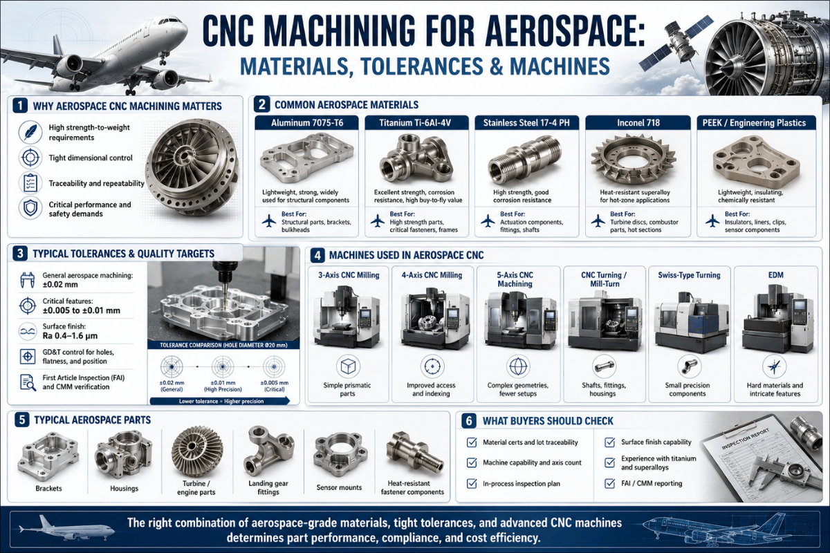
| コア材料 | Al 7075/6061/2024, Ti-6Al-4V, Inconel 718/625, 15-5/17-4 PH |
| 支配的なプロセス | 3- and 5-axis milling (VMC), CNC turning, grinding, EDM |
| 品質フレームワーク | AS9100D + NADCAP special processes + AS9102 First Article |
| Buy-to-fly (complex Ti) | 8:1 to 25:1 — up to 92–96% of the billet becomes chips |
航空宇宙用 CNC 加工とは何ですか?

Aerospace CNC machining involves computer numerical control machine tools — milling centers, lathes, grinders and EDM — to produce aircraft and spacecraft components from a billet, forging or casting. A CNC machine follows a programmed path to remove material with repeatable, micron-level accuracy, and the same manufacturing process makes simple brackets and complex parts alike.
Because most aerospace parts sit in life-sustaining systems, the work is governed by aerospace-specific quality standards rather than general shop practice — which is why CNC machining has become the method used in aerospace across aerospace applications, since the machining can achieve micron repeatability part after part.
Aerospace manufacturers use CNC machining technology because it involves consistent, micron accuracy that’s seldom achievable by hand, in contrast to the last two decades where this fastener style has become the foundation of aerospace CNC production. In aerospace machining, the essential requirement is consistency batch after batch, and this is just what computer controls provide.
CNC machining today dominates the aerospace supply chain for aircraft and aerospace vehicles because it does two things that the space vehicle can’t do without: it makes parts with tight tolerances, and it produces identical parts across a global fleet. Every component no matter how complex or simple, an aircraft’s wing box structure and an internal cockpit communications panel, are all from the same process. Common applications of aerospace CNC machining include structural parts such as wing ribs and engine parts such as turbine blades.
What is the difference between aerospace machining and standard CNC machining?
The physics of normal CNC machining are similar to those of aerospace CNC machining, but the aerospace machining process characteristics are added four requirements: tighter tolerances (in the range of 0.0002-0.0005 in compared to 0.005 in in general machining), challenging materials (titanium, Inconel, PH stainless rather than mild steel and 6061), full material traceability from mill certificate to finished part, and a quality system that has been audited for certification.
A component that would normally be dispatched after a brief caliper measurement in a regular shop now requires a First Article Inspection report, heat-lot traceability, and formal process validation before it can be installed. Research on precision machine tools confirms these micron tolerances depend on machine rigidity and thermal control, not the cutter alone, as shown in this precision five-axis machining study.
Aerospace Components Made by CNC Machining

We CNC mill every type of aerospace part for the entire plane; usually the machining route and the specific machine are determined by the part family. This can include a wide array of machined parts from complex turbine blades (which run on engines) to simpler structural airframe parts such as wing ribs to more detailed fittings in aerospace assemblies. This table show the common families and the route most machining operations use.
| コンポーネントグループ | 例 | Typical process / machine |
|---|---|---|
| Engine & powertrain | Turbine blades, blisks, impellers, fuel nozzles, casings | 5-axis milling + EDM (superalloys) |
| 構造上の | Bulkheads, wing ribs, spars, frames | 3- and 5-axis milling (VMC), high material removal |
| 着陸装置 | Axles, pistons, torque links, clevis assemblies | Multi-axis turning + milling (Ti, PH stainless) |
| Fuel & hydraulic | Manifolds, valves, metering parts, couplings | Turning + EDM (internal channels) |
| Avionics & interior | Enclosures, sensor mounts, brackets, seat-track supports | 3-axis milling, Swiss turning (small parts) |
In fact, patterns emerge that suggest which parts tend to work toward which machines. Structural parts (including airframe structures and Inconel turbine parts) need heavy, rigid machines-a stiff 5-axis mill. Pin and sleeve type parts-fasteners, bushings, and pins-often need to be run on turning centers or Swiss machines. Even if a shop only has 3-axis mills, they can produce plenty of aircraft parts-as long as they don’t involve contours. Engine parts-the ones in the turbofan (or turbo jet) itself-as well as surrounding airframe parts, are the most challenging to route-often to run multiple (and multi-process machining operations), like milling, turning and perhaps EDM-before shipping.
The machining processes behind CNC aerospace machining are widely used in aerospace and across the aerospace and defense supply chain, and multi-axis CNC milling is especially suited to parts with contoured geometries. Aerospace companies rely on CNC machining aerospace parts because the work must stay fully traceable; CNC machining is used in aerospace CNC machining workflows end to end, and CNC machining is central wherever critical engine parts and precision-machined CNC parts are involved. 5-axis CNC machining ensures the contours that lower-axis machines cannot reach, which is why modern aerospace CNC manufacturing — and a shop’s aerospace machining capabilities — are judged on this work. Many aerospace parts need secondary operations, and the tooling and fixtures themselves are CNC machined. Contoured engine parts like turbine blades and impellers reach their surfaces only with five-axis machining, as documented in this precision five-axis study.
Materials in Aerospace CNC Machining: Alloys and Machinability

Aerospace materials — the materials for aerospace structures and engines — are selected for strength-to-weight, fatigue resistance and temperature resistance, the same properties that make them difficult to machine. Across the aerospace industry the factor that most affects how a material machines is how it conducts heat at the cutting edge, and titanium and Inconel rank as the most difficult to machine of the common aerospace materials. Ti-6Al-4V conducts heat at just 6.7W / m・K, so the heat stays at the cutting edge instead of leaving with the chip — the root reason it cuts so slowly.
If you were to plot every aerospace alloy along two axes-thermal conductivity (ability to carry heat away from the cutting edge), and resistance to cutting-the general characteristics of their machining behaviour would “fall out.” At one end, aluminium (such as 7075-T6) readily gives up heat (130 W/mK) so the chip carries the heat away, and you’re able to turn several thousand surface meters per minute. With titanium (Ti-6Al-4V), you give up only 6.7 W/mK to the chips, a 1/20th rate, so the heat stays put at the edge of the cutter and surface speed generally comes down by a factor of 5 to 10. nickel superalloys like Inconel 718 live in the “worst case” end, featuring slow heat dissipation and rapid hardening, causing them to be turned more slowly than any other class of materials.
| 材料 | 熱伝導率 | Relative machining ease | 典型的な使用 |
|---|---|---|---|
| Aluminium 7075-T6 / 6061 / 2024 | 約130W/m·K | Easy (high SFM) | Ribs, brackets, housings, fuselage frames |
| 17-4 / 15-5 PH stainless | 約17~23 W/m·K | 穏健派 | Landing-gear parts, shafts, flanges |
| チタン Ti-6Al-4V | ~6.7W / m・K | Hard (heat at edge) | Airframe, engine parts, landing gear |
| インコネル718/625 | ~11 W/m·K + work-hardening | とても厳しい | Turbine blades, exhaust, heat shields |
High-performance polymers (PEEK, ULTEM) and carbon-fibre composites round out the materials for aerospace work — roughly half of a Boeing 787 airframe is composite — but metals still dominate load-bearing CNC work, and CNC machining helps a supplier carry the same alloy from prototype to production. For the metals this client’s customers cut most often, our deeper guides on machining aluminium 6061 and 7075 (NAIST) および machining 15-5 and 17-4 PH stainless cover speeds, feeds and tooling in detail.
Tolerances, AS9100 and Quality Standards

Tight tolerance is characteristic of aerospace engineering – but tolerances aren’t equally tight, with specified areas that need to be precise shown on the drawings. But there’s no value in over-tolerancing-there will be an additional cost that the customer doesn’t necessarily need, and to under-tolerance a seal face would be a safety issue, for example.
| フィーチャクラス | 標準許容範囲 |
|---|---|
| 構造部品 | ±0.001 in (25 µm) |
| エンジンコンポーネント | ±0.0002–0.0005 in (5–12 µm) |
| Fuel / hydraulic | ±0.0001–0.0003 in (2.5–7 µm) |
| 表面仕上げ | 2~8 µm Ra |
What is the tightest tolerance achievable in aerospace CNC machining?
A commonly well-maintained machine tool performing routine aerospace machining for milled and turned parts should reliably deliver tolerances in the region of 0.0002-0.0005 in (5-13 micrometres). Hitting these tolerances, and just as importantly repeating them part after part, is the most definitive demonstration of your capability as a machining provider to the aerospace market.
On especially tightly fitted features such as bearing journals, seal seats and fuel metering holes, tolerances of 0.0001 in (2.5 µm) or finer can be required and in such cases the finishing processes commonly include grinding or EDM as an addition to the milling operations. As the required tolerances become tighter, the limiting factor will cease to be the cutting tools, and become environmental and temperature control of both the machine and the workpiece – a mere 1° C difference in temperature will cause a 300-mm long aluminum component to expand or contract by some 7 micrometres – this is why the majority of precision inspection takes place in a climate controlled at 20° C (68° F).
Quality control procedures carry just as much weight as the actual cutting of parts. In the aerospace industry, AS9100 defines the Quality Management Standard for all aerospace organisations – it covers everything ISO 9001 does, and adds specific clauses related to Risk, configuration, and Traceability for the aerospace industry. In addition to this, companies providing special processes, such as heat treatments, coatings, welding, and non-destructive testing, will need a specific AS9100 approval for these processes as well as NADCAP (National Aerospace and Defense Contractors Accreditation Program) accreditation. First Article Inspection will confirm whether the first of the parts ordered have dimensions correct in accordance with the drawing before production of the batch can commence as per AS9102.
“NADCAP accreditation provides objective evidence that a supplier’s special process is tightly controlled, repeatable, and meets aerospace requirements.”
Performance Review Institute (Nadcap)
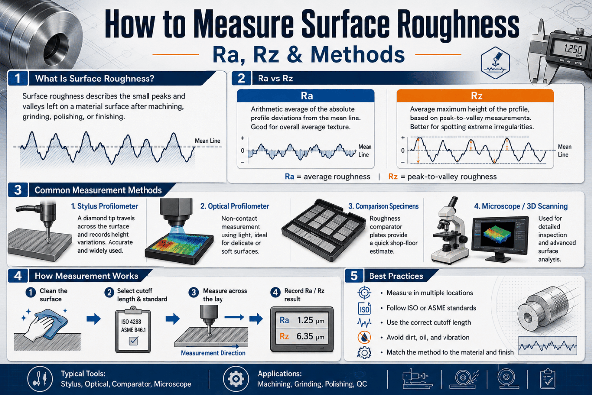
Think about inspectability when you’re designing parts, a hard feature to machine is also difficult to inspect. Consider having accessible datum points on your part that your CMM machine can easily access, be mindful about GD&T specifications (make sure it only applies to features where its relevant), and be sure to verify your surface finish by a proper measuring of it rather than making an assumption- see our guide on how to measure surface roughness (Ra) rather than judging by eye.
CNC Processes and Machines: 3-, 4- and 5-Axis, Milling and Turning

The bulk of aerospace machining work is carried out on either multi-axis machining centres or turning centres.CNC milling and CNC turning are the two primary process used, but machining with the hardest parts and features also requires grinding and/or EDM (Electrical Discharge Machining). As their names suggest, 5-axis multi-axis milling allows machining into several faces of a workpiece at once to create contoured parts, while turning is ideal for round ones. If a machine shop offer services within aerospace, they would also have both a machining centre for prismatic or contoured parts and a turning centre for those that are round.
| 部品形状 | 最適 | Why |
|---|---|---|
| Prismatic, single-face | 3軸VMC | Lowest cost; high material removal on plates and housings |
| Multi-face, prismatic | 4軸 / 3+2 | Indexes faces in one setup, cuts re-fixturing error |
| Contoured surfaces, undercuts | 5軸VMC | Reaches blades, impellers and pockets from any angle in one setup |
| Round / cylindrical | CNC turning / Swiss | Shafts, pins, fittings; ライブツール adds milling features |
3-axis vs 4-axis vs 5-axis CNC: which do aerospace parts need?
Use the simplest machine the part allow. 3-axis milling is ideal for flat and prismatic parts – plenty of brackets, plates and housings never require more. A 4th-axis (3+2 positioning) increases a VMC’s capabilities by allowing you to machine multiple faces in one setup – which eliminates the stack-up error created when refixturing. XNUMX軸加工 warrants its cost on complex, multi-sided contoured parts like turbine blades, impellers, and topology-optimised structures where a 3-axis machine simply can’t reach.
Here’s the contrarian truth most marketing machines omit: 5-axis isn’t always necessary, and it simply adds cost without value to simple prismatic parts. Even a strong vertical machining centre with 4th-axis preparation can service a good deal of typical aerospace work before you even require full simultaneous 5-axis capabilities. For round parts, a CNC旋盤 paired with the VMC will machine flats and cross-holes in the same chuck, with the addition of live tooling. In any type of machining work where a part has complex 3D surfaces – this is the territory where the 5-axis machine distinguishes itself and is used to produce intricate components such as forgings, completed blades and impellers – then 5-axis is required and no amount of tooling will help inferior lower-axis machines achieve what a 5-axis is meant to do.
Machine Requirements: What a VMC Needs for Aerospace Work

At this point most guides’ content ends. The primary concern for the aerospace engineers and buyers we encounter as machine builders-rather than a job shop-isn’t “who,” but “what does the machine have to do?” Aerospace CNC machining capabilities far exceed the requirements for a conventional machine shop, Aerospace CNC machining requires capabilities a conventional shop lacks, and aerospace designers lean on them; the manufacturing process in the aerospace world is also used in CNC tooling, where CNC machining is employed alongside the cutting and CNC machining is also a part of building the fixtures. and we identify five that determine a vertical machining centre’s suitability for aerospace production and the machining of tough alloys to aerospace tolerances.
- The Spindle Should Match the Alloy. For machining aerospace parts made from aluminum, the VMC’s spindle will need high RPM (12,000-24,000+) to allow for chip clearing and thin wall finishes; whereas Inconel and titanium require low RPM, high-torque spindle to effectively push tools through heat-trapping alloys. A single spindle rarely serves both ends of the spectrum successfully. Select the spindle based on the predominant aerospace material you run.
- Rigid Structure, Powerful Damping. Tough alloys with tighter tolerances necessitate machines that have sufficient rigidity and damping to minimise deflection and chatter. For instance, the addition of boxway construction, a sturdy, damped column, and other features will prevent chatter on heavy, high-feed cuts.
- Adequate Axis Travel and Work envelope Size. Ensure the working envelope or “work cube” is large enough to accommodate the largest component you’re likely to run along with necessary tooling clearance and fixturing. Machining large structural aircraft parts and subsequently running out of Z axis stroke mid program would be a disaster.
- Thermal Control and Stability. Holding micron-tight tolerances isn’t just about the hardness of your tools and the speed of your spindle. Thermal growth can be a fatal flaw that will negate the accuracy a tight tolerance machine tool. Look for models with thermal growth compensation of the spindle and column, plus thru-spindle coolant to manage temperature.
- 4th/5th-Axis and automation readiness. If you’re machining contoured parts and have been doing them without a 4th axis, then at minimum 3+2 positioning is going to be required. Lights out aerospace production demands sophisticated automation for in-process probing, tool management and pallet changers or bar feeds.
Run any potential aerospace machining center through this inspection to determine its ability to perform. If your intended machine has a spindle limit of 8,000 RPM, for example, then don’t try to machine aluminium with it. You wouldn’t invest in a poorly constructed frame with little stiffness to machine tough alloys, so apply that same degree of due diligence in selecting any VMC you’re looking to put to work in an aerospace environment. Explore the complete CNC milling machine range and you can compare the key spindle, work-envelope and rigidity parameters using the above specifications as a guide. Peer-reviewed work ties these micron results to spindle rigidity and thermal stability far more than to the cutting tool, as this precision machining study ドキュメント。
A buyer we worked with was spec-ing a VMC for titanium landing-gear fittings. On paper two machines looked identical, but one topped out at 8,000 RPM behind a 15 kW spindle while the other held 30 kW of torque down at 2,000 RPM. Run through the gate, only the high-torque machine could push a cutter through Ti-6Al-4V without stalling or chattering — the high-RPM machine would have been ideal for aluminium and a problem here. What decided it was spindle torque at low RPM, not the headline RPM number.
航空宇宙CNC加工における主な課題

Most of the trouble in aerospace work comes not from programming geometry, but from battling the material and the part’s own natural flexibility. You can almost certainly find these four problem areas repeated in any serious aerospace program. Titanium’s heat-and-chatter behaviour in particular is mapped in defence machining research such as NATO STO AVT-139.
- Heat at the cutting edge. Low thermal conductivity in titanium results in heat building up in the tool. This heat must be carried away with high-pressure coolant, achieved with sharp carbide cutters, and feed rates high enough to keep the chips moving off the cutting zone.
- Work-hardening. Inconel and titanium are notorious work-hardening alloys. If your tool dwells, even slightly, it will rub against the work and instantly harden the material at the tool path. Tool wear and breakage occur rapidly if feeds are reduced significantly enough to permit this – keep your tool cutting.
- Thin-wall deflection and chatter. Aerospace parts commonly have thin walls with deep internal pockets which can deflect and ring under cutting loads, resulting in chatter.
- Tool wear and cycle time. All high-strength aerospace alloys consume tools quickly. Tool-life monitoring and coating the carbide inserts can maintain dimensional integrity of the parts throughout an entire run.
A useful shop rule of thumb for machining thin walls: the support to the wall-width ratio should be at least 8:1 (reported in the July issue of モダンマシンショップ). Machine from two sides, in alternating depths of cut, and leave a small material pad until final passes so the wall is balanced across the depth of cut. Speeds and feeds, which must be carefully tailored to the alloy, and not the capabilities of your machine, are set out in our feeds and speeds guide.
On one job a 2 mm titanium rib wall kept chattering, and the finish came off looking like a record groove. Dropping to a 6 mm stepped depth of cut, alternating sides of the wall and switching to a climb-milling pass settled it; the wall held its profile once the tool stopped deflecting the unsupported section. The fix cost cycle time, but scrapping a near-finished titanium part costs far more.
Cost Factors and Choosing an Aerospace Machining Partner

Machining aerospace parts is expensive, but likely not for the reason most buyers think. Your machining service charge for use of the machine hourly, a relatively small cost.
In aerospace, “buy-to-fly ratio”-raw weight of material purchased versus the weight of the part that flies-is generally about 10:1, and in titanium for structural components, it can be 12:1-25:1. Put differently, the amount of material machined to chips may represent as much as 92-96% of purchased stock. Given the significant premium placed on titanium stock over that of softer materials, the cost of an aerospace component is most often dominated by the quantity of material acquired for machining, rather than its machine-time rate. This perspective immediately restructures how costs should be perceived. If your objective is cost reduction, target lowering the buy-to-fly (through the use of near-net forgings and hybrid stock) to the greatest possible extent.
- Material – Stock titanium and Inconel. High Buy-To-Fly Waste.
- Tolerance and Inspection – Tight Bands Create Slow Cuts. High levels of CMM and metrology inspection required.
- Volume – High-mix Low-volume – Low runs of parts means amortization is poor over set-up and programming costs.
- Certification Overhead – Compliance with Aerospace standards including First Articles. Real Labor required beyond just paperwork.
Before outsourcing your aerospace parts, always inquire about their credentials and past performance. You should see proof of AS9100D certification, any applicable NADCAP approvals (for special processes), an ITAR registration (for U.S. military aerospace programs), experience Machining your specific alloy and, most critically, a demonstrated history of successful First Article (FAI) completion on similar components. Selecting a CNC shop without a proven FAI history for your first article is a gamble when flight hardware is concerned; true CNC Machining delivers part-to-part consistency Component machining for aerospace and defense is unforgiving: the engine parts like turbine blades and the parts and assemblies around them are what aerospace machining involves, the parts for aerospace structures that machining supports across the build. only when a vendor’s process control systems prove themselves well beyond their compliance certificate.
A shop quoting a titanium structural bracket once assumed machine time would dominate the price. When they weighed the raw billet against the finished part, the buy-to-fly ratio came out near 8:1 — they were paying for eight kilograms of titanium to ship one. We rebuilt the quote around stock cost and removal time, and a near-net forging later cut the material bill by more than a third.
Trends Shaping Aerospace CNC Machining in 2026

This year’s tech force in aerospace machining isn’t one tech — it’s demand overcoming capacity. Demand for aerospace, as well as orders placed in that segment, are both increasing, while the aerospace labor market has experienced a severe lack in skilled workers, which have led to this demand as shops rush towards automation. Aerospace programs need more than what’s presently obtainable with existing aerospace CNC machines, and this is why machine shops are choosing to get on board with automation or consolidate to 5-axis capabilities. Shops that have avoided adoption this long will see a continuously growing cost difference with automation. Many simpler aerospace machine parts that are as a rule operated on basic CNC machines are now moving to automation-controlled machines. Across the aerospace sector, machining in aerospace is commonly used in the aerospace and defense base and is well suited for aerospace work; the aerospace industry demands more output, so modern aerospace manufacturing on modern CNC equipment, and CNC machining that enables aerospace programs, now does what older standard CNC lines could not. Hybrid additive-subtractive machining — building a near-net shape, then finishing critical surfaces — directly attacks the titanium buy-to-fly problem, an approach documented in additive-manufacturing patents such as US10828698B2.
There are three technological shifts arising from this demand for the aerospace machining sector. Lights-out machining allows for a small number of machinists to run more spindles while leaning on adaptive control technology to avoid tool waste. With advanced digital twins, heat and distortion can be simulated before any metal is cut. This additive hybrid machining process-in which machines make a close approximation before fine-tuning the essential edges — helps with the cost-effectiveness associated with expensive titanium by addressing buy-to-fly ratios directly. Aerospace industry interest in additive manufacturing for parts demonstrates this shift. When looking at machine procurement from the aerospace buyer’s perspective, there’s really only one way to go: look for machines that can handle automation, especially with probing features, to eliminate retrofitting costs later down the road.
よくある質問
Q: What certifications are required for aerospace machining?
回答を見る
Q: Is aerospace CNC machining expensive, and what drives the cost?
回答を見る
Q: How long does aerospace CNC machining take?
回答を見る
Q: Which aerospace parts are the most difficult to machine?
回答を見る
Q: Can you machine titanium on a standard VMC?
回答を見る
Q: What is an aerospace CNC machinist?
回答を見る
関連記事
参考文献と情報源
- Titanium Ti-6Al-4V Material Data SheetASM / MatWeb
- Buy-to-fly ratios in aerospace additive/subtractive manufacturingPMC (National Library of Medicine)
- Lifecycle analysis of titanium structural fittings (buy-to-fly 12–25:1)サイエンス
- Precision five-axis machine tools for complex surfacesPMC (National Library of Medicine)
- AS9100 Quality Systems, AerospaceSAEインターナショナル
- NADCAP Aerospace Quality Certificationsパフォーマンスレビュー研究所
- 10 Tips for Titanium (8:1 thin-wall ratio)モダンマシンショップ
このガイドを作成した理由
私たちは 立形マシニングセンターs and CNC lathes that aerospace shops run, so this guide is written from the machine side of aerospace CNC machining, what spindle, rigidity and thermal capability tight-tolerance titanium and Inconel work actually demand. The tolerance bands, the Ti-6Al-4V 6.7 W/m·K figure and the buy-to-fly ratios here are cited to public material and standards sources, not vendor claims. Reviewed by the ANTISHICNC technical team.