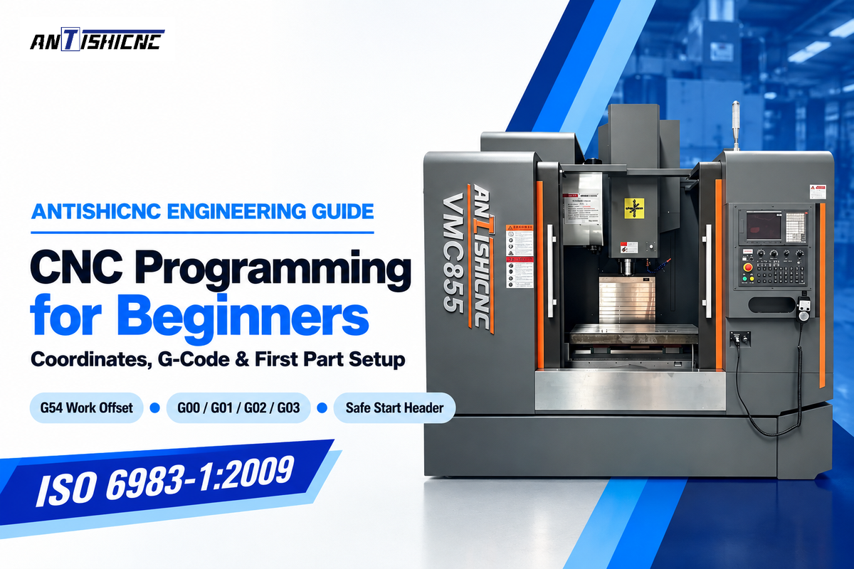





CNC programming for beginners is the process of writing a structured series of commands, standardized under ИСО 6983-1:2009 that direct a computer numerical control lathe or mill along X, Y, and Z toolpaths. At its core, cnc programming involves three foundational layers: selecting the part origin with a G54 work offset, commanding linear or circular motion with preparatory G-code commands (G00, G01, G02, G03), and switching hardware functions with miscellaneous M-codes (M03, M08, M30).
When programming a cnc turning center, the X word specifies workpiece diameter on diameter-programmed controls, whereas a 3-axis vertical mill pairs G54 with G43 H tool length compensation. Using our 8-Word Safe-Start Header template at program start-up and executing the 6-Stage First-Part Prove-Out sequence at a reduced rapid override gives the operator extra reaction margin before an errant offset reaches the chuck or vise.
1. How CNC Programming Works: Word-Address Syntax and the Three Programming Paths
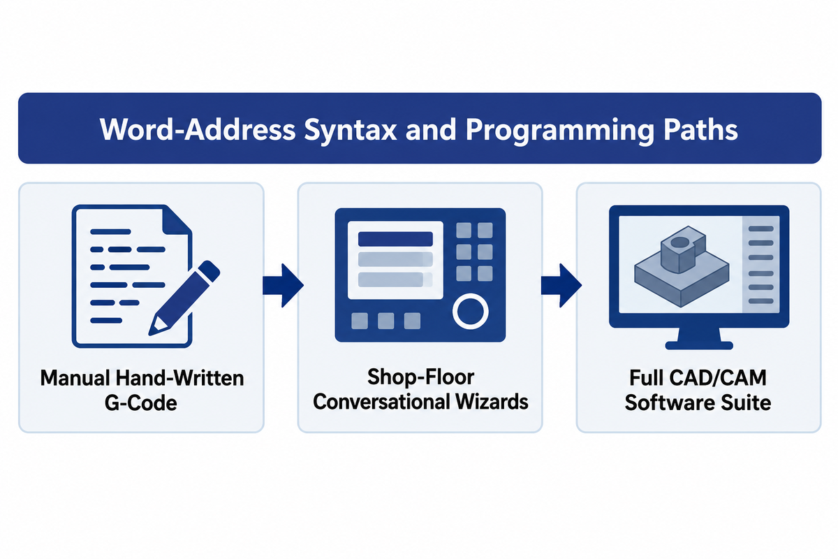
A CNC control on a cnc machine reads a part program as a sequential list of text lines called blocks, where each word combines an address letter (N, G, X, Y, Z, F, S, T, M) with a number per ИСО 6983-1:2009. Manual programming or conversational menus can handle simple turning, flat brackets, and indexed multi-axis positioning, while CAM generates toolpaths for complex contoured surfaces; an existing reusable program can also shorten preparation for a small batch.
Modern numerical control systems trace their syntax to the RS-274D format and the withdrawn ISO 6983-1:1982 first edition. As documented in the LinuxCNC RS274/NGC language overview, a two-word line such as G1 X3 moves the axis at the active cutting feed rate until X reaches 3 at the end of the move. Every block in this beginner’s guide ends with an end-of-block delimiter on Fanuc and Haas screens or a line break in plain text files.
In daily job-shop production, buyers who first learn about cnc programming often assume a novice must master 3D CAD software and post-processors before cutting a pin or bushing. More accurately, writing a simple program in g-code manually or using conversational CNC programming puts metal quickly in small batch runs of collars, shafts and bolt circles. Conversely, Cutting Tool Engineering notes that a Marubeni Citizen-Cincom L20E Swiss-style lathe with 7 cutting axes and up to 32 tools is difficult to program manually; comparing programming tools and software options shows why multi-channel synchronization and 3D sculptured molds rely on computer-aided manufacturing software.
| Address Word | Letter Function | Controller Action on Machine | Decimal & Syntax Rule |
|---|---|---|---|
Н10 |
Sequence / Block Number | Labels the line for operator search and restart reference | Integer address word |
Г01 |
Preparatory Motion Command | Activates modal linear cutting interpolation along target axes | Integer or fixed decimal (such as G54.1) |
X50.0 |
X-Axis Coordinate | In metric absolute mode, specifies a 50.0 mm diameter on a diameter-programmed lathe or an X coordinate on a mill | Explicit decimal point avoids least-input-increment interpretation |
Z-20.0 |
Z-Axis Coordinate | Moves parallel to the main spindle axis to coordinate Z-20.0 mm in metric absolute mode | Signed coordinate with explicit decimal point |
F0.15 |
Cutting Feed Rate | Specifies a feed value of 0.15 in the active feed mode (mm/rev in G99 or mm/min in G94) | Explicit decimal point recommended |
S1500 |
Spindle Speed / Surface Speed | Commands 1,500 RPM in G97 mode or 1,500 m/min in metric G96 mode (limit RPM via G50 on Fanuc/Haas or G96 D-word on LinuxCNC) | Integer value matched to active spindle mode |
T0101 |
Tool Station & Offset Call | Selects lathe turret Station 01 and applies Offset 01 | 4-digit integer on Fanuc lathes; T1 M06 on mills |
М08 |
Miscellaneous Machine Function | Requests flood coolant activation through the machine PLC | Integer address word |
; (EOB) |
End of Block Delimiter | Marks the end of a block on Fanuc and Haas console displays | Displayed as semicolon on Fanuc/Haas; newline in text files |
| Evaluation Dimension | Manual Hand-Written G-Code | Shop-Floor Conversational Wizards | Full CAD/CAM Software Suite |
|---|---|---|---|
| Ideal Part Geometry | 2-axis stepped shafts, bushings, washers, simple hole patterns | 2.5D pockets, bolt circles, thread milling, multi-step shafts | 3D contoured molds, impellers, 3+2 indexed and 5-axis parts |
| Typical Shop Application | Single-piece collars, fixture pins, and dedicated cycle macros | Short-run job-shop repair and prototype batches at the console | Recurring production runs and complex 3D CAD geometry |
| Preparation Workflow | Direct coordinate entry for a short turning or facing cycle | Interactive graphic menu prompts completed at the control | 3D model import, tool library setup, and post-processing |
| Spindle Idle Time Impact | Medium if typed at MDI; zero if written in a text editor offline | High unless programmed while a prior batch is running | Zero spindle downtime (programmed offline at engineering desk) |
| Representative Systems | Fanuc 0i-TF, Haas NGC, GSK 980TDi, LinuxCNC | Fanuc Manual Guide i, Siemens ShopTurn/ShopMill, Haas VPS | Autodesk Fusion, Mastercam, ESPRIT, Siemens NX CAM |
| Post-Processor Dependency | None (direct machine dialect execution) | None (built into the CNC controller firmware) | High (requires a machine-matched post-processor) |
| Line-Level Edit Control | Direct control over every dwell, retract, and clamp | Moderate (cycles compile into underlying ISO blocks) | Indirect (edits made in CAM parameters or post-processed file) |
| Software Licensing | Uses built-in controller editor or standard PC text editor | Included or ordered as a controller option at machine purchase | Personal/educational tier or commercial per-seat subscription |
| Operator Skill Prerequisite | Must know coordinate signs, modal groups, and nose compensation | Must understand cutting feeds, depths of cut, and tool offsets | Must master 3D CAD geometry, work coordinate systems, and G-code review |
Note that ИСО 6983-1:2009 is not intended for numerically controlled flame cutting and drafting machines used specifically and exclusively in the shipbuilding industry, and workflow choice in the matrix above shifts with part feature count and existing program libraries.
Is CNC programming easy to learn?
Yes, learning foundational CNC programming is approachable for a beginner who understands basic coordinate geometry and signed decimal numbers. Standard ISO 6983-1 word-address blocks follow fixed letter rules, such as Г01 for linear feed and X3 for a target coordinate. A new operator can read basic motion lines, set a Г54 datum, and step through a 2-axis turning or drilling program after structured simulator and console practice.
When you program a CNC machine, disciplined habits and routines help develop machining process judgment. Workholding systems, safe cutting speeds, and tool offsets require careful planning before the program is loaded into the machine tool. When machinists and programmers treat this programming language as a set of instructions, following a structured step-by-step guide helps maintain control when transitioning from a metal cutting simulator to actual metal cutting.
2. Cartesian Coordinate Systems (X/Y/Z), Absolute vs Incremental (G90/G91), and G54, G59 Work Offsets
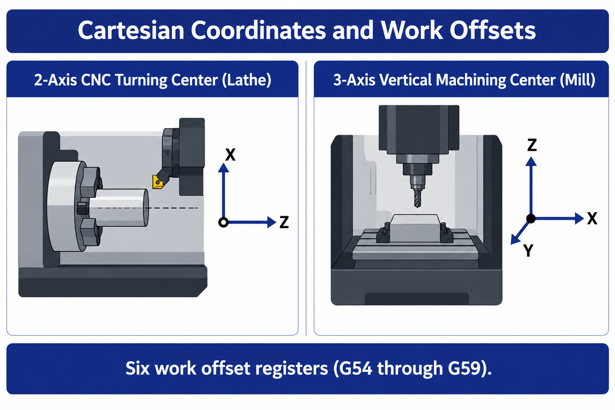
Conventional CNC lathes and vertical mills use right-handed Cartesian coordinate systems with the Z axis parallel to the main spindle axis; on a standard lathe, positive +Z points away from the headstock, and on a vertical mill it raises the tool away from the table. Six work offset registers (G54 through G59) relate the part datum to the machine coordinate system (G53).
Axis orientation and offset chains differ between turning and milling. Understanding what is CNC turning starts with recognizing that a standard 2-axis lathe uses the X (cross-slide) and Z (carriage) axes, and programs X as workpiece diameter on diameter-mode controls. Entering a 25.0 mm radius value into a diameter-programmed lathe X word commands a 25.0 mm diameter instead of 50.0 mm, cutting to half the intended diameter and risking insert fracture. On a 3-axis vertical mill, the table moves in X and Y while the spindle head travels vertically in Z. The Haas Mill Operator’s Manual illustrates this with a basic Tool 1 cut taking a 0.100 in (2.54 mm) depth of cut along a straight path from X = 0.0, Y = 0.0 to X = -4.0, Y = -4.0 relative to the top-right G54 corner.
In the University of Florida MAE CNC Milling Machine Tutorial, lab instructors explain that if the wrong tool offset is used for a tool, a CNC mill could crash. On Fanuc and Haas mills, G54 selects the work coordinate system, while G43 H01 activates positive tool length compensation using the value stored in offset register H01. Heidenhain and native Siemens controls use a separate tool-table and datum-shift syntax rather than G43 H.
| Coordinate Parameter | 2-Axis CNC Turning Center (Lathe) | 3-Axis Vertical Machining Center (Mill) |
|---|---|---|
| Primary Motion Axes | X (radial cross-slide) and Z (longitudinal spindle axis) |
X (table left-right), Y (table front-back), Z (spindle up-down) |
| X-Axis Value Meaning | Programmed in diameter on diameter-mode lathes (X50.0 = 50.0 mm diameter) | Direct linear distance from the active G54–G59 X0 datum |
| Typical Z0 Work Datum | Finished front face of the turned bar (cuts into stock are negative -Z) | Top face of the stock or fixed vise jaw reference surface |
| Absolute vs. Incremental Syntax | Fanuc Type A uses X/Z for absolute and U/W for incremental moves | Switches modal states between G90 (absolute) and G91 (incremental) |
| Tool Offset Activation | 4-digit T0101 selects Tool 1 and applies geometry and wear offset 01 | T1 M06 loads Tool 1; G43 H01 activates length compensation register 01 |
| Zero Return Command | G28 U0.0 W0.0 specifies zero incremental intermediate displacement before reference return | G28 G91 Z0.0 (followed by G90) or G53 G00 Z0.0 retracts Z first |
Beginners must understand how G28 interprets its intermediate point. As GCodeTutor and CNC Training Centre document for mills using G90 and G91 distance modes, G28 G91 Z0.0 specifies zero incremental Z displacement before returning Z to reference, and G28 G91 X0.0 Y0.0 Z0.0 returns all 3 axes X, Y, and Z. If G90 absolute mode is left active and a programmer writes G28 Z0.0 (or G28 Z20.0 in metric mode), the machine first moves to the intermediate position of Z0.0 (or 20 mm above Z0 in Z) before going to the reference position.
How do I start learning CNC programming?
Start learning CNC programming by practicing coordinate setup on a single piece of CNC equipment (either a 2-axis lathe or a 3-axis vertical mill) before moving to multi-axis CAM software. As Gitaidu Yatzen, you’ll begin by plotting 2D X/Y/Z tool positions on graph paper. When you learn cnc programming basics, plot 2D X/Y/Z tool positions on graph paper first, verify your blocks in a desktop G-code backplotter second, and practice touching off G54 work offsets and tool lengths at the machine console third.
To learn the basics of CNC programming without risking spindle damage, make a short facing and drilling part program by hand and key it line by line into a simulator such as NC Viewer or CAMotics. Understanding these cnc programming basics enables you to trace how each modal command modifies the active state and to check the distance-to-go readout to gauge how much metal is yet to be removed.
3. Core G-Code and M-Code Reference: G00, G01, G02/G03, G71, G96/G97, and Auxiliary Commands
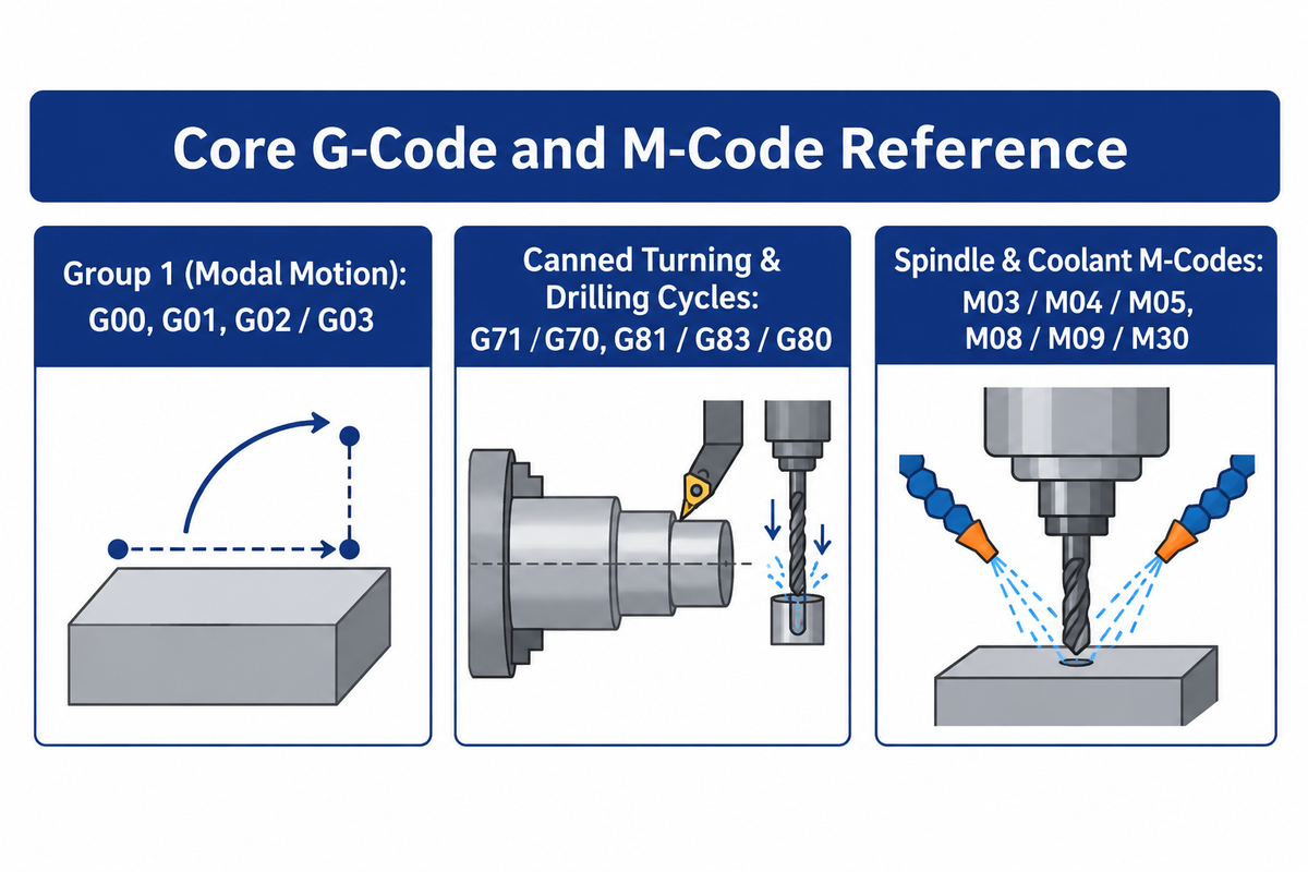
Twenty-four preparatory G-codes and seven miscellaneous M-codes, grouped into 14 functional rows, cover the core motion, cycle and auxiliary operations in everyday turning and 3-axis milling. While multiple G-codes from different modal groups can share a block, Haas and many standard Fanuc configurations execute one M-code per block.
По данным LinuxCNC G-Code Reference Manual, motion commands in Modal Group 1 (G00, G01, G02, G03) stay active across subsequent lines until replaced by another Group 1 code. For example, once G01 F20.0 Z-0.1 sets linear cutting feed, the next coordinate block continues cutting at F20.0 without retyping G01. For an extended machine-side lookup, see our G-code and M-code reference list.
| Код | Modal Group / Persistence | Primary Engineering Function | Lathe vs. Mill Behavior & Safety Caveat |
|---|---|---|---|
Г00 |
Group 1 (Modal Motion) | Rapid positioning traverse in air | Used for non-cutting positioning; multi-axis rapid moves may follow a non-linear dog-leg path |
Г01 |
Group 1 (Modal Motion) | Linear cutting interpolation at feed F | Synchronizes axes along a straight line; requires an active F feed rate word |
Г02 / Г03 |
Group 1 (Modal Motion) | Clockwise (G02) / Counterclockwise (G03) circular arc | Uses R radius or center offsets (I/J in G17 XY, I/K in G18 ZX, J/K in G19 YZ); full circles use I/J/K |
G17 / G18 / G19 |
Group 2 (Modal Plane) | Selects XY (G17), ZX (G18), or YZ (G19) plane | Vertical mills default to G17 (XY); standard 2-axis CNC lathes operate in G18 (ZX) |
G20 / G21 |
Group 6 (Modal Units) | Inch input (G20) vs. Millimeter input (G21) | Coordinate words, feed rates, and offset values must match the active unit system |
G28 / Г53 |
Group 0 (Non-Modal) | Reference return (G28) / Machine coordinate motion (G53) | G28 moves through the programmed intermediate point before homing; G53 interprets coordinates in the machine frame |
Г40 / G41 / G42 |
Group 7 (Modal Comp) | Cancel (G40), Left (G41), Right (G42) radius compensation | Applies or cancels milling cutter radius or lathe tool-nose radius compensation on a lead-in or lead-out move |
G43 H__ / G49 |
Group 8 (Modal Length) | Activates (G43) or cancels (G49) tool length offset | Standard mill practice pairs the H register number with the active T tool number (e.g., T2 M06 with G43 H02) |
Г71 / Г70 |
Canned Turning Cycles | Multi-pass stock roughing (G71) and finish pass (G70) | Lathe specific: removes bar stock in radial passes and leaves a programmed finishing allowance |
Г81 / Г83 / Г80 |
Group 9 (Canned Cycles) | Drilling cycle (G81), peck drill (G83), cancel cycle (G80) | Command G80 after the hole pattern is finished so subsequent positioning moves do not plunge |
Г96 / Г97 & Г50 |
Spindle Control | Constant surface speed (G96), constant RPM (G97), spindle speed clamp (G50 on Fanuc/Haas) | Lathe specific: pair G96 with a preceding G50 S____ maximum RPM clamp; use G97 for center drilling at X0 |
М03 / M04 / М05 |
Spindle Relay Control | Spindle CW (M03), CCW (M04), Spindle Stop (M05) | Confirm tool hand and insert orientation before starting the spindle with M03 or M04 |
М06 |
Tool Change Command | Executes automatic tool changer (ATC) swap on mills | Standard on vertical mills (T1 M06); Fanuc lathes typically index the turret via T0101 |
М08 / M09 / М30 |
Coolant & Program End | Flood coolant ON (M08), OFF (M09), End & Rewind (M30) | Per UF MAE Haas SL-10 rules, specify M30 at the end of the program to denote program end and rewind |
Common Mistake, The Fanuc Missing Decimal Point Trap (Parameter 3401.0 DPI): As CNC Training Centre documents, Fanuc Parameter 3401 BIT 0 (DPI) governs integer coordinate interpretation. When Parameter 3401 BIT 0 is set to 1, numbers work like a calculator so X5000 is taken as 5000 mm. When Parameter 3401 BIT 0 is set to 0, integer coordinates without a decimal point are taken in least input increments (such as microns in metric mode, where X5000 is taken as 5000 microns or X5.0 mm, and X50 becomes 0.050 mm, a 1,000-fold reduction at a 0.001 mm increment, or a 10,000-fold reduction at a 0.0001 in increment where X5 becomes 0.0005 in).
How Do G-Code and M-Code Work Together?
G-code and M-code work together by dividing a CNC machine’s control architecture between the motion interpolator and the programmable logic controller (PLC). Preparatory G-codes specify the geometric path to follow and axis feed rate, and define the limits of offsets. Miscellaneous M-codes perform auxiliary functions such as switch on/off the coolant, index the tool changer, and control the direction of turning the spindle.
With metric input and feed-per-revolution mode active, a block such as N20 G01 X36.0 Z-25.0 F0.20 M08 ; commands linear interpolation to X36.0 and Z-25.0 at 0.20 mm/rev and requests flood coolant through M08. Use g-codes to command tool motion and m-codes to trigger hardware actions in a structured sequence throughout the entire machining process, from raw bar clamping to final part unload.
4. Calculating Spindle Speed (RPM), Cutting Feed Rate, and the G50 Lathe Speed Clamp
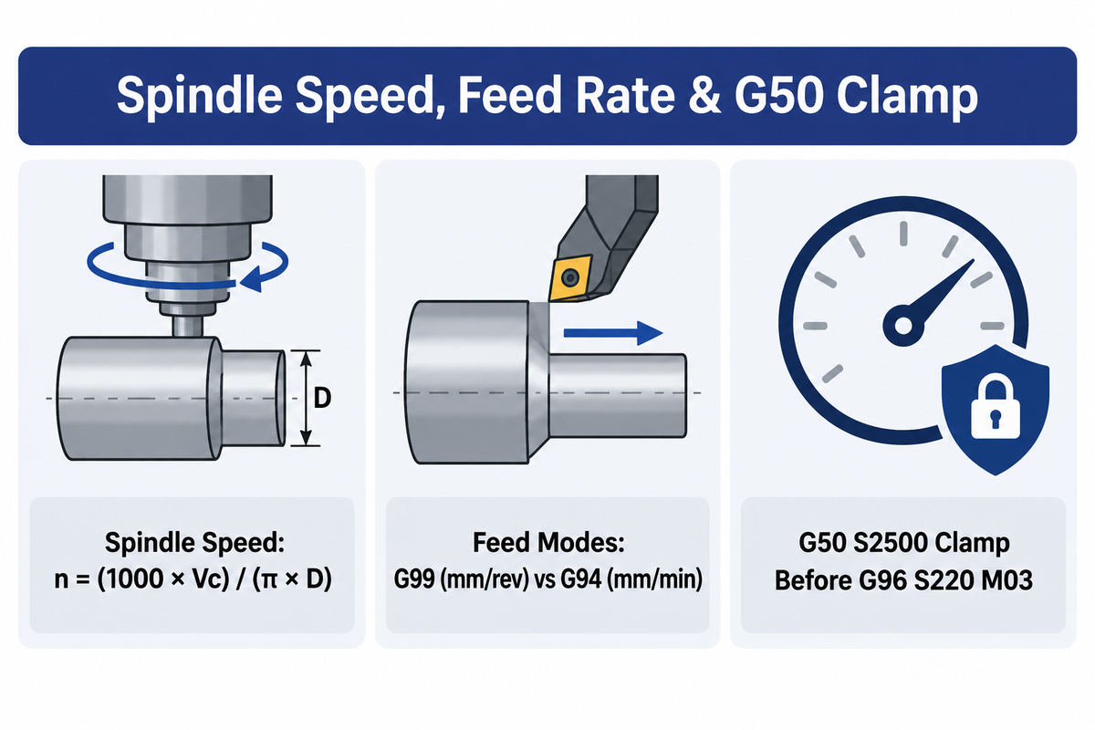
Spindle speed is calculated from the tool manufacturer’s cutting speed (Vc in m/min) and the workpiece or cutter diameter (D in mm) using n = (1000 × Vc) / (π × D), which gives 1,401 RPM when turning a 50.0 mm bar at 220 m/min. On Fanuc Type A and Haas CNC lathes, a G96 Constant Surface Speed operation uses a preceding G50 S____ maximum RPM clamp matched to the setup, whereas LinuxCNC specifies the spindle ceiling with a D word inside G96.
Sandvik Coromant’s general turning formulas cite specific cutting force Kc0.4 at a feed of 0.4 mm/r with a general material constant mc = 0.29. When the tool’s entering angle (KAPR) is 75 degrees or more, sin KAPR is approximately 1 and the simplified equation for the tangential force can be used. In turning programs, feed per revolution is typically commanded in G99 mode (fn in mm/rev), while in vertical milling programs the table feed per minute is commanded in G94 mode (Vf = n × fz × z in mm/min).
Worked Calculation Example (Assumed Inputs for 6061-T6 Aluminum): Suppose you’re calculating speeds and feeds for two operations on 6061-T6 aluminum using assumed carbide tooling inputs. For Operation A (2-axis lathe OD turning on a 50.0 mm diameter bar at Vc = 220 m/min and fn = 0.20 mm/rev), spindle speed at the outer diameter is n = (1000 × 220) / (3.1416 × 50) = 1,401 RPM, resulting in a carriage feed rate of 1,401 × 0.20 = 280.2 mm/min. At a diameter of 20.0 mm, maintaining 220 m/min would require 3,501 RPM; placing G50 S2500 before G96 S220 M03 caps actual spindle speed at 2,500 RPM as the tool approaches X0. For Operation B (3-axis milling with a 12.0 mm, 3-flute carbide end mill at Vc = 200 m/min and fz = 0.08 mm/tooth), spindle speed is n = (1000 × 200) / (3.1416 × 12) = 5,305 RPM, and table feed is Vf = 5,305 × 0.08 × 3 = 1,273 mm/min (G94 F1273.0).
As the Mount Hood Community College Constant Surface Speed guide explains, under G96 the commanded RPM increases as the X diameter gets smaller. Without a speed clamp, such as G50 (or G92 S____ in ISO Dialect A / Siemens), facing to X0 can drive the spindle to the machine’s configured top speed, while centrifugal force can reduce the gripping force of an external-gripping 3-jaw chuck. Conversely, CSS is not necessary for drilling operations that start at X0 and do not change part diameter; centerline tools use G97 constant RPM mode.
How can I learn CNC coding?
You can learn CNC coding by combining speed-and-feed calculations with hands-on exercises where you write g-code for three benchmark geometries: a turned stepped shaft, a faced flange with a chamfer, and a milled rectangular pocket with corner holes. Writing these three part programs teaches you how to calculate spindle speed, select G94 versus G99 feed modes, and organize tool offsets.
A personal reference notebook can pair commands with their operating conditions: on a lathe using G50 for spindle limiting, the clamp before G96 stays within the chuck, workholding, and machine limits; in a G83 drilling sequence, the cycle remains active for subsequent holes until canceled by G80. Running those files in a backplotter builds reliable programming skills before you step up to the machine console.
5. Writing a Safe Start Block for CNC Lathes and Vertical Machining Centers
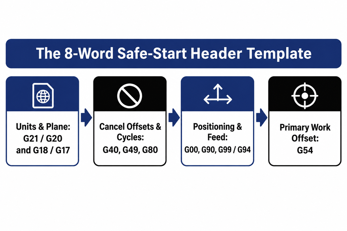
A safe start block sets units, plane selection, work coordinates, and compensation cancels at program entry and tool changes so modal states left by a previous job don’t cause unintended motion. In the Haas Mill Operator’s Manual, a basic safe startup block reads G00 G90 G17 G40 G49 G54, which can be paired with unit, cycle-cancel, and feed-mode words in our 8-Word Safe-Start Header Template.
Machinists on Practical Machinist note that crashes often happen when an operator stops a cycle mid-program to index an insert, or accidentally starts a subprogram instead of the main program while incremental mode, cutter radius compensation, or a drilling cycle remains active. A complete safe-start reset block placed above every tool change in CNC milling programming establishes a consistent modal state before the tool approaches the part. The University of Florida Haas SL-10 CNC lathe resource manual also notes that parenthetical comments can’t exceed 80 characters.
| Reset Category | 2-Axis CNC Lathe Header Word | 3-Axis VMC (Mill) Header Word | Modal State Established or Canceled |
|---|---|---|---|
| 1. Measurement Units | G21 (Metric) or G20 (Inch) |
G21 (Metric) or G20 (Inch) |
Locks coordinate and feed interpretation to millimeter or inch units |
| 2. Interpolation Plane | G18 (ZX Turning Plane) |
G17 (XY Milling Plane) |
Selects the active plane for circular arcs (G02/G03) and radius compensation |
| 3. Radius Comp Cancel | Г40 (Cancel Nose Comp) |
Г40 (Cancel Cutter Comp) |
Cancels active G41 or G42 cutter/nose radius compensation offsets |
| 4. Length Offset State | On lathes using this T-code format, T0100 selects tool station 1 and cancels tool offsets; T0101 selects station 1 and activates offset 01 |
G49 (Cancel Length Offset) |
Cancels prior mill tool length compensation before calling the new G43 H register |
| 5. Canned Cycle Cancel | Г80 (Cancel Canned Cycles) |
Г80 (Cancel Canned Cycles) |
Cancels active drilling or boring cycles before positioning moves |
| 6. Positioning Mode | Г00 (with absolute X/Z words) |
G90 (Absolute Distance Mode) |
Establishes rapid positioning and cancels G91 incremental distance mode on mills |
| 7. Feed Rate Mode | G99 (Feed per Revolution) |
G94 (Feed per Minute) |
Sets turning feed to mm/rev (or in/rev) and milling feed to mm/min (or in/min) |
| 8. Work Coordinate | Г54 (Primary Work Offset) |
Г54 (Primary Work Offset) |
Selects the primary G54 work coordinate datum for the setup |
6. Your First Complete CNC Program: Stepped Aluminum Shaft Turning Walkthrough
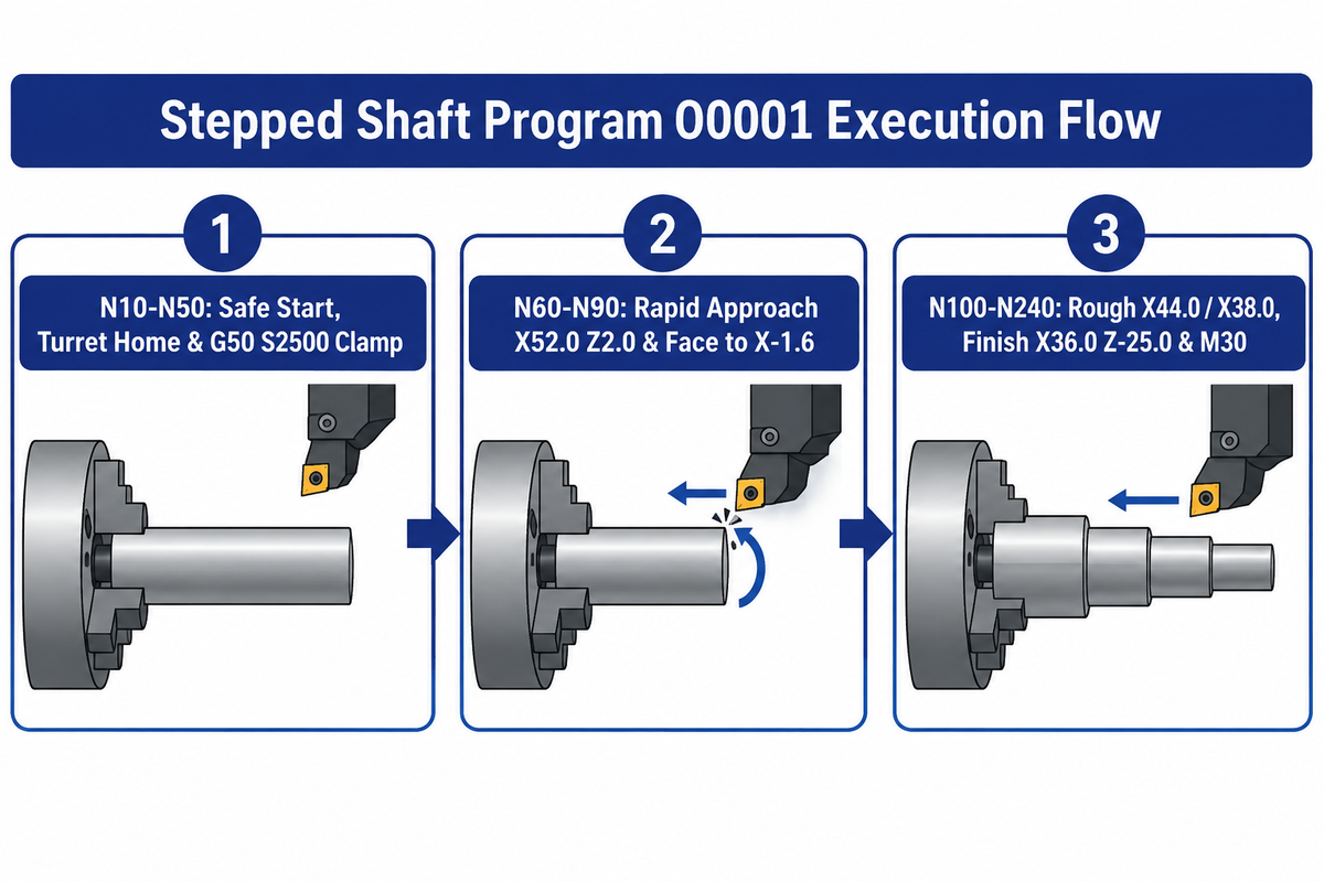
A complete, runnable first CNC program combines the safe start header, spindle clamp, approach clearance, cutting passes, and home retract into sequential blocks from N10 to N240. In this walkthrough example, a 2-axis Fanuc/Haas lathe faces a 50.0 mm diameter aluminum bar to Z0.0, turns a 36.0 mm diameter by 25.0 mm step with a 1.0 mm × 45° chamfer, and returns to reference home.
%
O0001 (FIRST PART: ALUMINUM STEPPED SHAFT OD 50MM TO 36MM) ;
N10 G21 G18 G40 G80 G99 G54 (SAFE START HEADER METRIC ZX PLANE) ;
N20 G28 U0.0 W0.0 (INCREMENTAL RETURN TO TURRET HOME) ;
N30 T0101 (SELECT OD ROUGH/FINISH TOOL 01 WITH R0.8MM INSERT OFFSET 01) ;
N40 G50 S2500 (CLAMP MAXIMUM SPINDLE SPEED AT 2500 RPM) ;
N50 G96 S220 M03 (CONSTANT SURFACE SPEED 220 M/MIN SPINDLE CW) ;
N60 G00 X52.0 Z2.0 M08 (RAPID TO 2MM CLEARANCE OUTSIDE BAR & COOLANT ON) ;
N70 G00 Z0.0 (POSITION AT Z0 FINISHED PART FACE PLANE) ;
N80 G01 X-1.6 F0.15 (FACE PAST CENTERLINE BY 2X R0.8 NOSE RADIUS) ;
N90 G00 Z2.0 (RETRACT 2MM IN Z BEFORE RADIAL RAPID) ;
N100 G00 X44.0 (RAPID TO FIRST ROUGHING PASS DIAMETER 44MM) ;
N110 G01 Z-25.0 F0.22 (ROUGH TURN 44MM DIAMETER TO 25MM LENGTH) ;
N120 G01 X51.0 (FEED RADIALLY CLEAR OF BAR SHOULDER) ;
N130 G00 Z2.0 (RAPID BACK TO Z2.0 FRONT CLEARANCE PLANE) ;
N140 G00 X38.0 (RAPID TO SECOND ROUGHING PASS DIAMETER 38MM) ;
N150 G01 Z-25.0 F0.22 (ROUGH TURN 38MM DIAMETER LEAVING 2MM ON DIA) ;
N160 G01 X51.0 (FEED CLEAR OF SHOULDER) ;
N170 G00 Z2.0 (RAPID BACK TO Z2.0 FRONT CLEARANCE) ;
N180 G00 X34.0 (RAPID TO START OF 1MM X 45 DEG FRONT CHAMFER) ;
N190 G01 X36.0 Z-1.0 F0.12 (CUT 1MM X 45 DEG CHAMFER AT FINISH FEED) ;
N200 G01 Z-25.0 (FINISH TURN 36.0MM DIAMETER TO Z-25.0 SHOULDER) ;
N210 G01 X52.0 (FINISH FACE SHOULDER OUT TO 52MM CLEARANCE) ;
N220 G00 Z5.0 M09 (RETRACT Z5.0 AND TURN COOLANT OFF) ;
N230 G28 U0.0 W0.0 M05 (RETURN TO TURRET HOME AND STOP SPINDLE) ;
N240 M30 (END OF PROGRAM AND REWIND TO TOP) ;
%
Notice two shop-floor details in this программирование токарных станков с ЧПУ walkthrough. First, on line N80, the facing cut feeds past X0.0 to X-1.6 (twice an assumed 0.8 mm insert nose radius) so that the cutting edge clears the spindle centerline to avoid leaving a center nub. As the lathe facing guide from Industrial Monitor Direct warns, changing the X endpoint can mask a center-height error, and changing height can mask an incorrect nose radius; always verify tool center height and stored nose radius first. Second, when programming internal boring bars on subsequent operations, Sandvik Coromant’s rule of thumb states that the tangential cutting force Ft shouldn’t exceed 90% of the maximum load stated for the bar used.
| Block Range | Active Modal State | Target Coordinates | Physical Machine Verification Point |
|---|---|---|---|
N10–N20 |
G21 G18 G40 G80 G99 G54 |
U0.0 W0.0 (Home) |
Turret is at reference position before indexing Tool 1 |
N30–N50 |
T0101, G50 S2500, Г96 |
Station 1 active | Spindle starts CW; RPM clamp set to 2,500 RPM maximum |
N60 |
Г00 Rapid, М08 Охлаждающая жидкость |
X52.0 Z2.0 |
Single-block pause point: check that insert stops 2.0 mm in front of part face |
N70–N90 |
G01 F0.15 Лицом |
Z0.0 → X-1.6 → Z2.0 |
Spindle reaches 2,500 RPM cap near X0; faces clean across centerline |
N100–N130 |
G01 F0.22 Rough Pass 1 |
X44.0 Z-25.0 |
Removes 3.0 mm radial depth (6.0 mm off diameter) along 25.0 mm step |
N140–N170 |
G01 F0.22 Rough Pass 2 |
X38.0 Z-25.0 |
Leaves 1.0 mm radial stock (2.0 mm on diameter) for finishing |
N180–N210 |
G01 F0.12 Finish & Chamfer |
X34.0 → X36.0 Z-1.0 → Z-25.0 |
2-axis linear move cuts 1.0 mm × 45° chamfer then finishes 36.0 mm diameter |
N220–N240 |
Г00, G28, M09, М05, М30 |
Z5.0 → U0.0 W0.0 |
Coolant off, turret returns to reference point, spindle stops, program rewinds |
7. First-Part Prove-Out: Single-Block, Dry Run, and the 6-Stage Crash Prevention Checklist
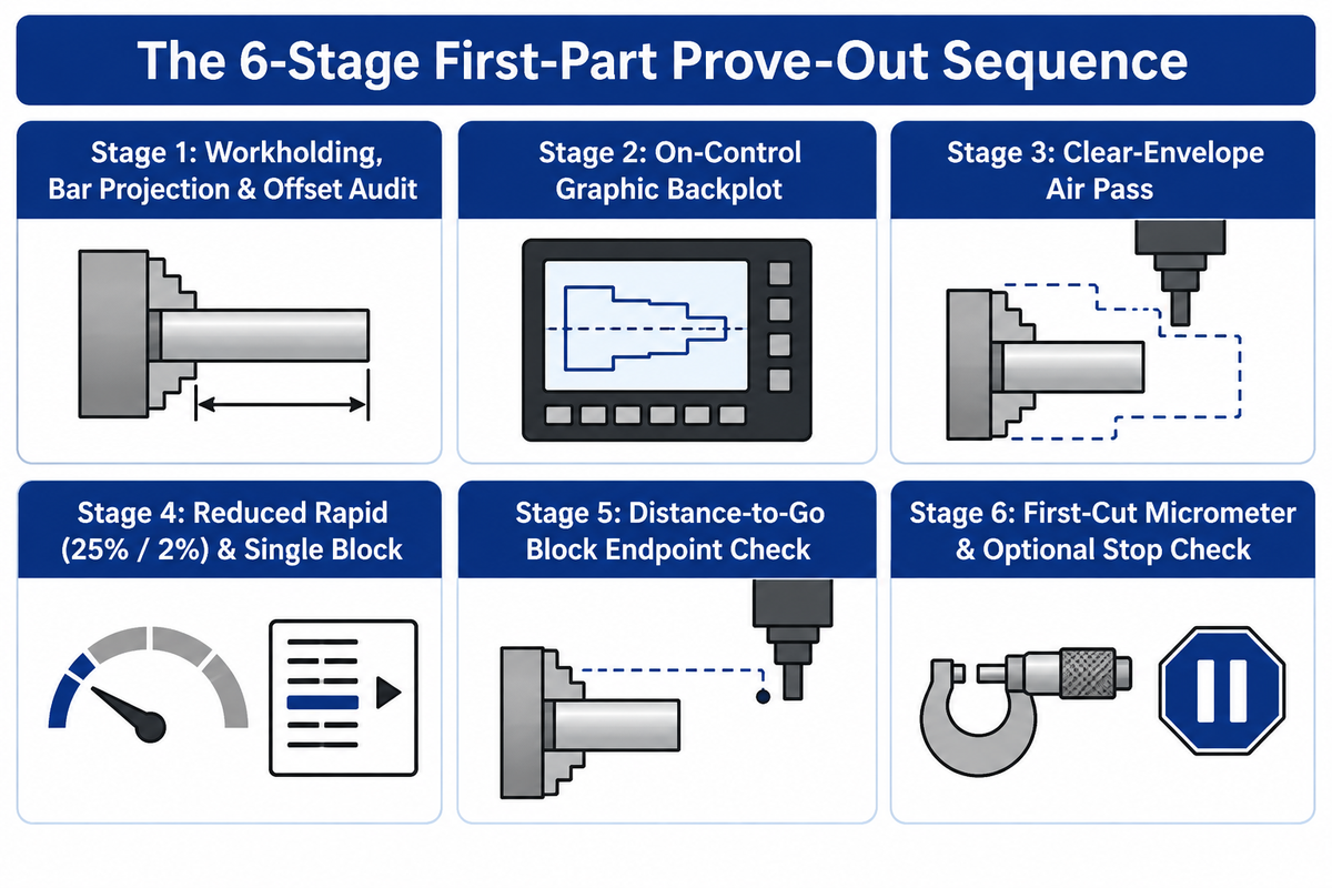
Proving out a new CNC program uses the 6-Stage First-Part Prove-Out Sequence: verifying workholding and offsets, running graphic simulation, testing clearance in air, setting Rapid Override to 25% (or 2% on high-speed machines), stepping in Single Block mode, and checking the Distance-to-Go display.
At a constant rapid traverse of 24 to 48 m/min (approximately 945 to 1,890 in/min), an axis covers a 100 mm gap in 0.125 to 0.25 seconds once up to speed. On Practical Machinist’s crash-prevention thread, experienced machinists emphasize Rule #1: set the Rapid-Override to 25% (or 2% on high-speed machines like a Brother Speedio) and program consistent clearance planes such as 0.1 in above the top of the part and a 4.0 in master clearance plane.
“Rule #1 – Set the Rapid-Override to 25% (or whatever makes sense on your machine- 2% if we’re talking a Brother Speedio, etc.).”
| Prove-Out Stage | Console Switch & Offset Setting | Operator Verification Action | Failure Caught Before Impact |
|---|---|---|---|
| Stage 1: Workholding, Bar Projection & Offset Audit | Spindle OFF; inspect workholding and Offset Page, including chuck jaws and bar stock on lathes | On lathes, verify jaw grip length, confirm bar stock never projects unsupported past the rear spindle bore, and check applicable work and tool offsets; on mills, verify workholding and check G54 and G43 H signs where supported | Prevents unsupported rear bar-whip hazards, jaw interference, and Z offset sign errors |
| Stage 2: On-Control Graphic Backplot | Open Dedicated Graphics Simulation Screen (axes stationary) | Run program through controller graphics plot to inspect rapid approach vectors and cycle retracts | Spots gross coordinate scaling errors, reversed G02/G03 arcs, and missing G80 cancels |
| Stage 3: Clear-Envelope Air Pass | Establish clearance for the entire approach, tool-change, and retract paths before the air pass; on a lathe, a Z work-offset shift moves the path along the spindle axis | Step through the cycle in air with coolant OFF (M09) while checking turret/spindle clearance | Checks spindle speed clamps, tool index clearance, and motion direction away from the part |
| Stage 4: Reduced Rapid (25% / 2%) & Single Block | Restore verified G54 datum; select 25% Rapid, or 2% or an equivalent low rapid speed for high-speed machines, with Single Block ON | Advance one block at a time with hand on Feed Hold while monitoring clearance to the part | Slows rapid approach speed to give the operator time to initiate a feed-hold deceleration stop |
| Stage 5: Distance-to-Go Block Endpoint Check | Pause with Feed Hold above the part; read Position Screen | Compare the remaining Distance-to-Go for the current block against the tool tip’s distance to the programmed target plane | Reveals if the programmed block endpoint lies deeper than the intended clearance plane |
| Stage 6: First-Cut Micrometer & Optional Stop Check | Engage Optional Stop (M01); run first cutting pass | Execute rough and finish pass, pause at M01, measure diameter with a micrometer, and trim the wear offset | Verifies part dimension before releasing the cycle to continuous automatic execution |
8. Best Beginner G-Code Simulators, Backplotters, and Entry-Level CAM Software
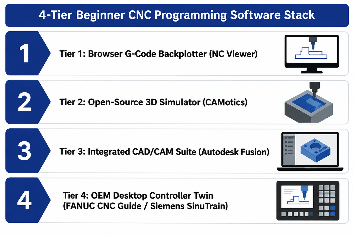
Beginner CNC programming software divides into four distinct functional categories: browser-based line backplotters (NC Viewer), open-source 3D material-removal simulators (CAMotics), integrated CAD/CAM suites (Autodesk Fusion), and OEM desktop controller twins (FANUC CNC Guide, Siemens SinuTrain). Pairing a CAM generator with a G-code backplotter verifies both geometry and posted output.
A common beginner mistake is assuming a clean animation inside CAM software proves the posted program is safe. As CGTech VERICUT’s G-code simulator guide explains, basic simulators like NC Viewer and CAMotics check simple G-code, 3D toolpaths, or 2D line plots, while full machine simulation systems replicate real-world G-code and machine behavior. Reading and backplotting the posted .nc file helps catch an unintended G28 Z0.0 intermediate move in G90 mode or a missing G43 H tool-length call before loading the file into the cnc control.
| Software Tool | Functional Tier | Turning & Milling Support | Licensing & Key Technical Boundary |
|---|---|---|---|
| NC Viewer | Tier 1: Browser G-Code Backplotter | 2D line plots & 3D wireframe toolpaths | Free web app; steps line-by-line through X/Y/Z coordinates without 3D solid stock removal |
| CAMotics | Tier 2: Open-Source 3D Simulator | 3-axis milling & engraving material removal | Free open-source desktop software; visualizes 3D cut stock, does not model turret/chuck collisions |
| Autodesk Fusion | Tier 3: Integrated CAD/CAM Suite | 2.5-axis & 3-axis milling, turning, FFF additive | Personal-use tier (since October 1, 2020) and educational licenses support 2.5D/3D milling and turning; the personal-use tier restricts rapid moves and automatic tool changes |
| FANUC CNC Guide / Siemens SinuTrain | Tier 4: OEM Desktop Controller Twin | Lathe (0i-TF / ShopTurn) & mill (0i-MF / ShopMill) | PC training twins that emulate industrial keypads, offset registries, and conversational screens |
Lightweight backplotters and open-source 3D stock simulators (NC Viewer and CAMotics) plot programmed coordinates and cut geometry but do not model full machine kinematics, turret housing clearance, or chuck jaw collision envelopes.
What is the best CNC program for beginners?
The best software stack for a beginner combines NC Viewer or CAMotics for backplotting hand-written G-code with Autodesk Fusion for learning integrated 3D CAD and CAM software toolpath generation. Simultaneously using these products allows the user to code a simple rectangular pocket or stepped shaft manually and validate it against post-processed CAM output.
Based on the Autodesk Fusion (personal use) policy (effective from October 1, 2020), the personal tier offers standard 3D design tools along with 2.5-axis milling and 3-axis milling as well as turning. Adding an OEM controller twin (i.e. FANUC CNC Guide or Siemens SinuTrain on a desktop PC) allows the user to practice offset entry and cycle start keystrokes for the physical machine.
9. Selecting Beginner-Friendly CNC Controllers and Entry-Level Industrial Machines
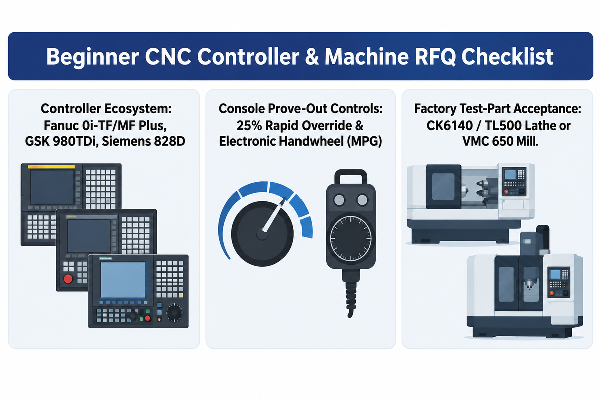
When ordering an entry-level industrial CNC lathe or vertical machining center, specify a controller with standard ISO 6983 G-code support, on-screen graphic simulation, and conversational guidance, specifically Fanuc 0i-TF Plus or GSK 980TDi for turning, Fanuc 0i-MF Plus for milling, or Siemens SINUMERIK 828D for either platform.
When evaluating machine types for a training cell or growing job shop, consider controller ergonomics, machine programming workflows, and mechanical rigidity. Conversational CNC technology, whose object-oriented control software classes were detailed across a 39-frame microfiche appendix in U.S. Patent US5453933A, allows operators to generate part programs via interactive graphic menus while retaining standard G-code execution. On the mechanical side, Токарные станки с ЧПУ, like the ANTISHICNC CK6140/CK6150 flat-bed and TL500 slant-bed machines, as well as 3-axis вертикальные обрабатывающие центры like the VMC 650 (rated for ±0.005 mm positioning accuracy with thermal compensation and high-speed options of up to 22,000 RPM spindle speed and 48 m/min rapid traverse), are outfitted with Fanuc, Siemens, or GSK controls. Consulting the ANTISHICNC technical team and machine support engineers helps match controller options and post-processors to your part drawings.
| RFQ Specification Item | Target Engineering Requirement | Beginner Crash-Prevention & Training Benefit |
|---|---|---|
| Controller Ecosystem | Fanuc 0i-TF Plus or GSK 980TDi (lathes); Fanuc 0i-MF Plus (mills); Siemens 828D (lathes/mills) | Supports ISO 6983 G-code syntax, with CAM post-processors matched to the configured controller and machine |
| Conversational Option | Fanuc Manual Guide i or Siemens ShopTurn / ShopMill enabled | Lets operators program shafts, threads, and pockets via graphic prompts at the console |
| On-Screen Graphics Check | 2D/3D Toolpath Graphics Simulation screen | Supports Stage 2 visual toolpath verification on the console before moving axes |
| Decimal Parameter Setup | Record Fanuc Parameter 3401.0 (DPI) setting on delivery sheet | Clarifies whether integer coordinates use calculator-style or micron input increments |
| Rapid Override Control | Dedicated console rapid override switch (including 25% and low-speed settings) | Provides immediate rapid speed reduction during Stage 4 first-part prove-out |
| Electronic Handwheel (MPG) | Detachable pendant MPG with fine, medium, and coarse step increments | Allows operators to jog axes incrementally while observing tool tip clearance at the part |
| Tool Setter / Probe Interface | Tool setter/probe interface requirement for VMC 650 or TL500 | With a compatible measuring device and measurement software installed, measured tool dimensions can populate the tool geometry offset table, reducing manual data entry; the program still calls the tool and offsets |
| Data Transfer & Memory | USB port and Ethernet DNC interface for part program transfer | Simplifies transferring post-processed CAM files from engineering PCs to the control |
| Factory Test-Part Acceptance | Machining trial on customer’s sample drawing (such as CK6140 shaft or VMC 650 plate) | Delivers the machine with a proven part program, fixture layout, and setup documentation |
Часто задаваемые вопросы
How long does it take to learn CNC programming for a beginner?
A beginner can learn to read basic ISO 6983-1 word-address blocks, set G54 work offsets, and prove out simple 2-axis turning or 3-axis drilling programs after initial simulator and console training. Reaching full shop-floor independence, including multi-tool setups, G71 roughing cycles, cutter radius compensation, and 3-axis CAM post-processing, requires ongoing hands-on machining practice across multiple part families.
Should a beginner learn manual G-code before CAD/CAM software?
Yes. Even in modern manufacturing shops that generate complex toolpaths in CAD/CAM software, the operator at the machine console must read G-code to verify safe start headers and G43 tool length calls, adjust feeds or speeds, and recover after a broken insert. Having an understanding of core G-codes and M-codes first helps avoid blind faith in post processor output.
What is the difference between G90 absolute and G91 incremental programming?
On controls that use G90 and G91 for distance mode, G90 interprets X, Y, and Z coordinates for ordinary work-coordinate moves in your CNC program relative to the active work offset origin (e.g. G54), whereas G91 commands a relative move from the tool’s current position. Note that Fanuc Type A lathes use X and Z for absolute coordinates and U and W for incremental moves.
Can I use the same G-code program on any CNC machine?
No. While ISO 6983 standardizes the core motion words that cnc machines use like G00 and G01, canned cycles, reference-return codes, and macro variables vary across Fanuc, Siemens, Haas, and GSK controllers, and each machine has distinct axis travel limits and tool changer syntax.
Why does Fanuc G-code require a decimal point on coordinate values?
As detailed in Section 3 under Parameter 3401 BIT 0 (DPI = 0), Fanuc controls configured in traditional integer mode interpret coordinate words without a decimal point in units of the machine’s least input increment rather than whole millimeters or inches. On a metric setup with a 0.001 mm increment, writing X5000 is read as 5000 microns (5.0 mm) and writing X50 is read as 0.050 mm, a 1,000-fold reduction. On an inch setup with a 0.0001 in increment, writing X5 without a decimal is read as 0.0005 in, a 10,000-fold reduction. During a rapid G00 approach or a G01 cutting pass, that coordinate discrepancy drives the tool toward the spindle centerline or part face instead of stopping at the intended diameter. Writing explicit trailing decimals on dimensional coordinates (such as X50.0, Z2.0, and F0.15) prevents this scaling error.
Ссылки и источники
- ISO 6983-1:2009, Automation systems and integration: Numerical control of machines, Program format and definitions of address words, Part 1 Международная организация по стандартизации
- ISO 6983-1:1982 (Withdrawn), Numerical control of machines: Program format and definition of address words Международная организация по стандартизации
- RS274/NGC G-Code Language Overview LinuxCNC Open-Source Documentation Project
- CNC Milling Machine & Tool Offset Tutorial University of Florida Department of Mechanical and Aerospace Engineering (Design and Manufacturing Laboratory)
- G-Code Modal Groups and Motion Reference Manual LinuxCNC Open-Source Documentation Project
- CNC Lathe Programming & Setup Resources University of Florida Department of Mechanical and Aerospace Engineering (Design and Manufacturing Laboratory)
- U.S. Patent US5453933A, Conversational CNC Control System Architecture United States Patent and Trademark Office (via Google Patents)