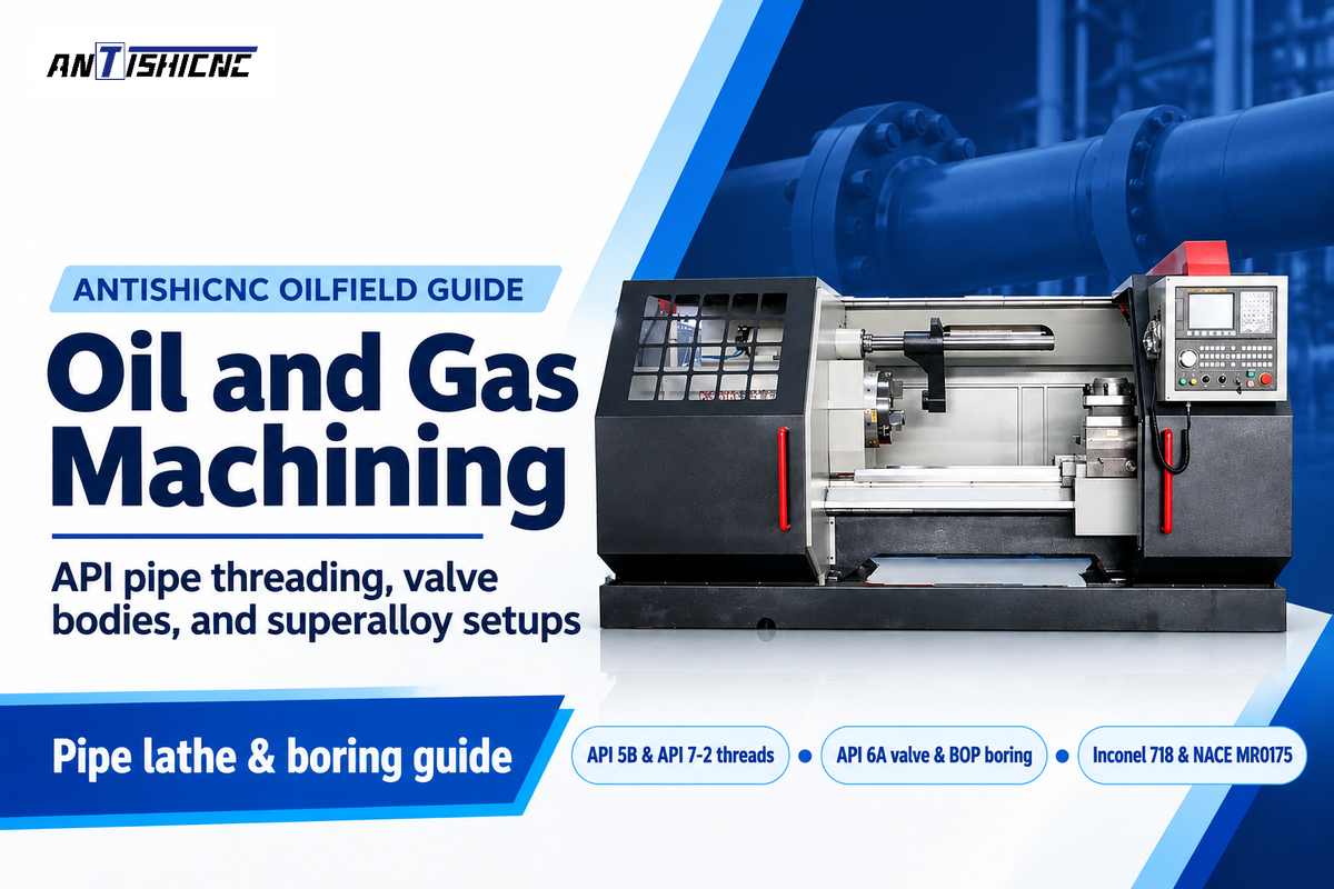






Oil and gas machining covers the heavy-duty CNC turning, deep-hole boring, and multi-axis profiling of high-pressure drilling, pipeline, and wellhead hardware governed by API 5CT, API 7-2, and API 6A standards. Producing gas-tight thread seals and sour-gas resistance requires double-chuck big-bore pipe lathes holding ±0.025 mm per 25.4 mm lead accuracy, 70 to 100 bar coolant for Inconel 718 and Super Duplex 2507, and rigid box-way horizontal boring mills.
The joints of downhole tools often fail around 4,000 meters below the seabed and blowout preventer bonnets often fail at service pressures in excess of 15,000 psi. Many of these failures can be traced back to the shop floor of the machine facility. Unlike general structural metal working, components built involved in the extraction and refining of petroleum products operate in the presence of cyclic torsional shock, exposure to hydrogen sulfide and extreme temperatures in excess of 200°C. In this engineering guide, we explore machine tools and machining practices required to manufacture oilfield equipment without scrap or tool failures.
1. Upstream, Midstream, and Downstream Oil and Gas Machining Requirements
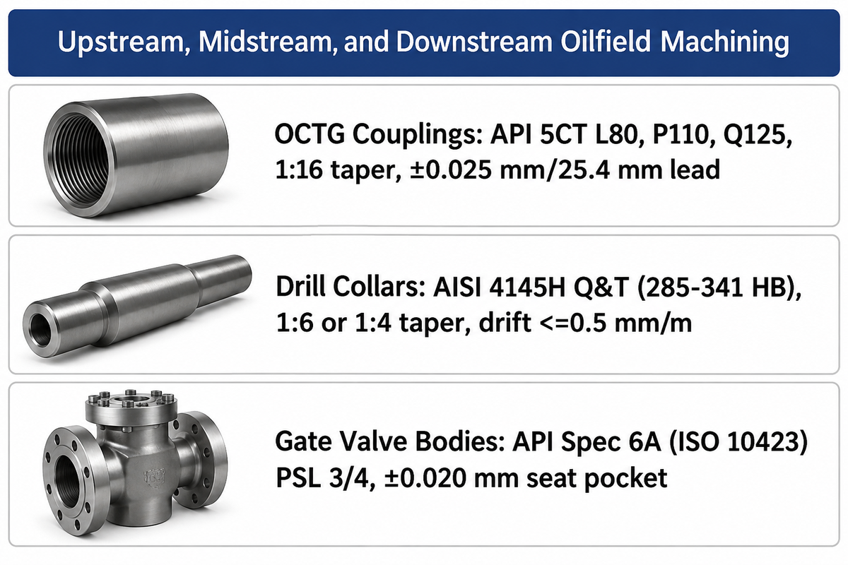
Heavy-duty metal cutting plays a significant role in keeping drilling and refining facilities online. Subcontractors (machining services) must qualify every spindle setups against API metallurgical rules. Understanding a supplier’s (machining capabilities) offerings start with understanding the differences (oil and gas operations) from industrial manufacturing. Advanced (machining solutions) integrated box-way boring tools with automated metrology and high-output (precision machining) bored tools may prevent premature fatigue in downhole strings.
The petroleum industry breaks component manufacturing into three divisions: upstream (exploration and production), midstream (pipeline transport), and downstream (refining and petrochemical). Heat-lot traceability and non-destructive testing are required in all three divisions, but the types of parts (geometry and alloys), code cases, and standards change drastically from the drill bits to the refinery manifolds.
In upstream activities, parts and components must endure high rotational torque and abrasive drilling mud, as well as bottom-hole hydrostatic pressure. Machinists work with long tubular forging and bar stock and turn rotary shouldered connections on drill collars, as well as gun-drill internal wiring channels on measurement-while-drill (MWD) housings and profile spiral blades of stabilizers. Downhole failures often lead to fishing operations, which costs rig operators $50,000 to $150,000 per day; therefore, bore and thread standoff leave no room for error.
Midstream infrastructure focuses on fluid conveyance and pressure containment across thousands of kilometers of transmission pipe. Machine shops serving midstream buyers turn raised-face and ring-type-joint weld-neck flanges under ASME B16.5 and ASME B16.47, bore large trunnion-mounted ball valve housings, and finish pigging launcher closures. Downstream plants introduce severe thermal cycling and chemical attack, requiring high-alloy pump parts, compressor impellers, and heat-exchanger tube sheets.
To help process planners match part families to the correct machine tool platform, the Oilfield Component & CNC Machine Architecture Selection Matrix below outlines nine main oilfield component types in terms of their governing standards, alloys, and tolerance bands.
| Component Type | Operating Sector | Primary Alloy Grade | Governing Standard | Critical Dimensional Tolerance | Primary CNC Machine Platform |
|---|---|---|---|---|---|
| OCTG Casing and Tubing Couplings | Upstream Well Construction | API 5CT L80, P110, Q125, 13Cr | API Spec 5CT / API Spec 5B | 1:16 taper; ±0.025 mm/25.4 mm lead | Double-chuck big-bore pijp draaddraaibank |
| Drill Collars and Heavy-Weight Drill Pipe | Upstream Rotary Drilling | AISI 4145H Q&T (285–341 HB) | API Spec 7-1 / API Spec 7-2 | 1:6 or 1:4 taper; bore drift <=0.5 mm/m | Double-chuck oil country lathe + BTA deep-hole drill |
| MWD and LWD Sensor Housings | Upstream Directional Drilling | Non-magnetic Cr-Mn stainless, BeCu | API Spec 7-2 / OEM Spec | ±0.013 mm seal bore; Ra <= 0.8 µm | 5-axis turn-mill center + gun drilling machine |
| Integral Blade Drilling Stabilizers | Upstream Bottom-Hole Assembly | AISI 4145H + tungsten carbide hardfacing | API Spec 7-1 | +0.00 / -0.40 mm blade OD gauge | 4-axis / 5-axis heavy turn-mill center |
| PDC and Tricone Drill Bit Bodies | Upstream Rock Destruction | AISI 4140, 4330V, matrix powder | API Spec 7-1 / API Spec 7-2 | ±0.025 mm cutter pocket angularity | 5-assig bewerkingscentrum |
| Gate Valve Bodies and Christmas Trees | Upstream Wellhead and Subsea | AISI 4130, F6NM, Inconel 625 clad | API Spec 6A (ISO 10423) PSL 3/4 | ±0.020 mm seat pocket; Ra <= 0.8 µm groove | Box-way horizontal boring mill with U-axis head |
| Blowout Preventer (BOP) Ram Blocks | Upstream Well Control | Forged 4130 / 4340 + CRA weld overlay | API Spec 16A / NACE MR0175 | ±0.025 mm ram cavity parallelism | Table-type horizontal boring mill (5–15 ton load) |
| Trunnion Ball Valves and Weld-Neck Flanges | Midstream Pipeline Transmission | ASTM A105, A350 LF2, Duplex 2205 | API Spec 6D / ASME B16.5 | 23° ring groove flank; ±0.13 mm pitch diameter | Vertical turret lathe (VTL) / heavy slant-bed lathe |
| Frac Pump Fluid Ends and Impellers | Upstream Stimulation and Downstream | 4330V, 17-4 PH, Super Duplex 2507 | API Spec 610 / ASME BPVC | ±0.015 mm intersecting cross-bore alignment | 5-axis horizontal machining center |
Compliance documentation for all nine component categories is as stringent as physical geometry. According to API Specification 6A for Product Specification Levels PSL 3 and PSL 4, equipment rated for working pressures from 10,000 to 20,000 psi (69 to 138 MPa) must include full certification of EN 10204 3.1, charpy V-notch impact tests, and 100% volumetric inspections using ultrasonic and/or radiographic means. Machine shops place unique serial codes on each setup sheet, enabling traceability to the forging mill certificate for each cutting pass.
What components are manufactured for oil and gas applications?
Components manufactured for oil and gas applications span upstream downhole tools (drill collars, MWD/LWD sensor housings, mud motor rotors, integral blade stabilizers, and PDC drill bits), wellhead pressure control hardware (API 6A gate valves, Christmas trees, tubing hangers, and blowout preventer bodies), midstream pipeline connectors (ASME B16.5 flanges and trunnion ball valves), and downstream refinery equipment (frac pump fluid ends, multi-stage centrifugal pump shafts, and compressor impellers).
All the machined components require specific workholding and spindle torque profiles. Long, tubular drill-stem elements rely on through-spindle rotary turning, and blocky, multi-ton valve forgings rely on horizontal boring tables with the ability to index four faces in a single set-up.
2. API Pipe Threading Lathes: Machining BTC, LTC, STC, and Rotary Shouldered Connections
Gespecialiseerd machining for oil tubulars demands synchronized dual-chuck workholding. Proven cnc machining solutions eliminate manual taper attachment drift on 12-meter casing joints. Shops offering certified cnc machining services calibrate thread standoff gauges before every shift. Within the oil and gas sector, pipe mills deploy dedicated oil and gas machining solutions to chase 5-TPI Buttress profiles without flank chatter. Every batch of machined parts undergoes 100% profile scanning.
In the oilfield supply chain, precision threading is by far the most volume turning activity. Each casing string, production tubing joint and section of drill pipe is supported by hundreds of thousands of pounds of suspended weight and sealing internal gas pressure. These connections are covered by two main standards: API Spec 5B for casing, tubing, and line pipe threads, and API Spec 7-2 for drill connections.
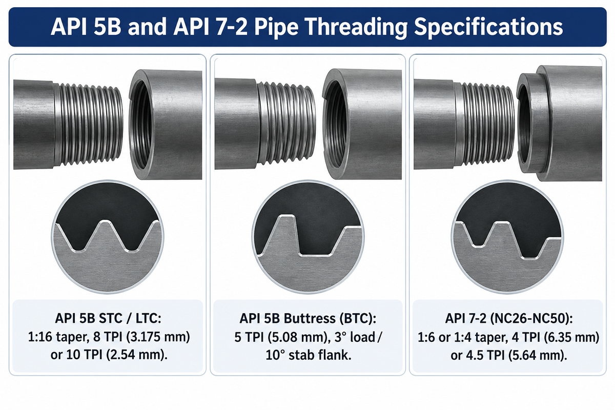
API Spec 5B identifies three classic thread profiles: Short Thread Casing (STC), Long Thread Casing (LTC), and Buttress Thread Casing (BTC). STC and LTC both use a rounded 60° V-thread profile with 8 or 10 TPI, and a 1:16 taper (0.75 in. per foot). Buttress threads (BTC) switch to an asymmetric saw-tooth profile (5 TPI, with a 3° load flank and a 10° stabbing flank) that transmits much higher axial tension without jumping threads. Buttress threads are used to transfer high axial tension without running the risk of jumping (by passing) threads. For high-pressure gas wells, shops also cut special high pressure connections that use a modified buttress thread, along with a precision metal-to-metal radial seal with an internal torque shoulder.
API Spec 7-2 covers heavy rotary shouldered connections (such as Numbered Connections NC26 through NC50, Regular REG, and Full Hole FH) machined onto drill pipe tool joints and drill collars. Because drill strings transmit massive rotational torque to the rock bit, API 7-2 threads use steeper tapers (1:6 or 1:4 on diameter, equivalent to 2.0 or 3.0 in. per foot) and coarse 4-TPI or 5-TPI pitches. Here, the thread form itself doesn’t seal the fluid; instead, the thread pulls the box face and pin shoulder together under high make-up torque to form a rigid, pressure-tight friction seal across the flat torque shoulder.
| Connection Standard and Type | Primary Oilfield Application | Thread Taper Ratio (on Diameter) | Standard Pitch (TPI / mm) | Lead Tolerance (per 25.4 mm) | Primary Sealing Mechanism |
|---|---|---|---|---|---|
| API 5B Short / Long Round (STC / LTC) | Surface and intermediate casing, tubing | 1:16 (0.75 in./ft) | 8 TPI (3.175 mm) or 10 TPI (2.54 mm) | ±0.025 mm (±0.001 in.); cumulative ±0.076 mm | Thread compound interference between crests and roots |
| API 5B Buttress Thread (BTC) | Deep tension casing strings (up to 13-3/8 in.) | 1:16 (0.75 in./ft) | 5 TPI (5.08 mm); 3° load / 10° stab flank | ±0.025 mm (±0.001 in.) per inch | Flank interference + API thread compound |
| API 7-2 Numbered Connections (NC26–NC50) | Drill pipe tool joints, drill collars, subs | 1:6 (2.0 in./ft) or 1:4 (3.0 in./ft) | 4 TPI (6.35 mm) or 4.5 TPI (5.64 mm) | ±0.025 mm (±0.001 in.); shoulder flat <=0.015 mm | High-compression metal-to-metal external torque shoulder |
| Proprietary Premium OCTG Connections | HPHT gas production tubing and sour casing | 1:16 to 1:12 variable | 5 to 8 TPI hooked or wedge flank | ±0.013 mm (±0.0005 in.); seal nose Ra <= 0.8 µm | Cone-to-cone or sphere-to-cone metal seal + torque shoulder |
You can’t cut these connections accurately on a standard single-chuck lathe. A Range 3 casing joint or drill collar measures 9 to 12 meters long and weighs up to 3,000 kg. If you grip one end in a standard chuck and support the far end with a tailstock center, the pipe sags under its own weight and whips violently at 150 RPM. Dedicated CNC pipe threading lathes solve this by passing the pipe straight through an oversized hollow spindle bore (spanning from 130 mm up to 560 mm) equipped with synchronized front and rear chucks. As experienced oilfield machinists note in Practical Machinist pipe threading setups, dialing both front and rear four-jaw chucks within 0.03 mm (0.0012 in.) total indicator reading (TIR) while supporting the outboard tail with roller steady rests eliminates pipe whip and taper ovality.
To re-chase worn drill pipe tool joints in a repair shop an electronic thread-repair teach-in cycle is used. The operator jogs the insert into an existing thread groove, locks the spindle encoder angle (C-axis synchronization) to the Z-axis ballscrew position, and skim cuts (0.15 to 0.30 mm) from the damaged flanks and torque shoulder without cross-threading the original lead. For images of different configurations of chuck jaws, take a look at our article on lathe chuck types en 3-jaw vs 4-jaw chuck configurations.
What is the best CNC machine for drilling and casing pipe components?
The best CNC machine for drilling and casing pipe components is a double-chuck big-bore CNC pipe threading lathe (sometimes called an oil country lathe) with a hollow spindle bore of 130 mm to 560 mm, synchronized front and rear four-jaw chucks, a two-speed or four-speed geared headstock producing 3,000 to 12,000 Nm of low-RPM torque, and hardened cast-iron box ways.
A dedicated two-axis double-chuck pipe lathe is a better choice than a more expensive five-axis center for casing couplings and rotary tool joints, since it provides rigid dual-end clamping close to the cutting turret and CNC controlled taper-threading cycles for API 5B and API 7-2.
3. Upstream Downhole Tool Machining: Non-Magnetic Drill Collars, MWD Housings, and Stabilizers
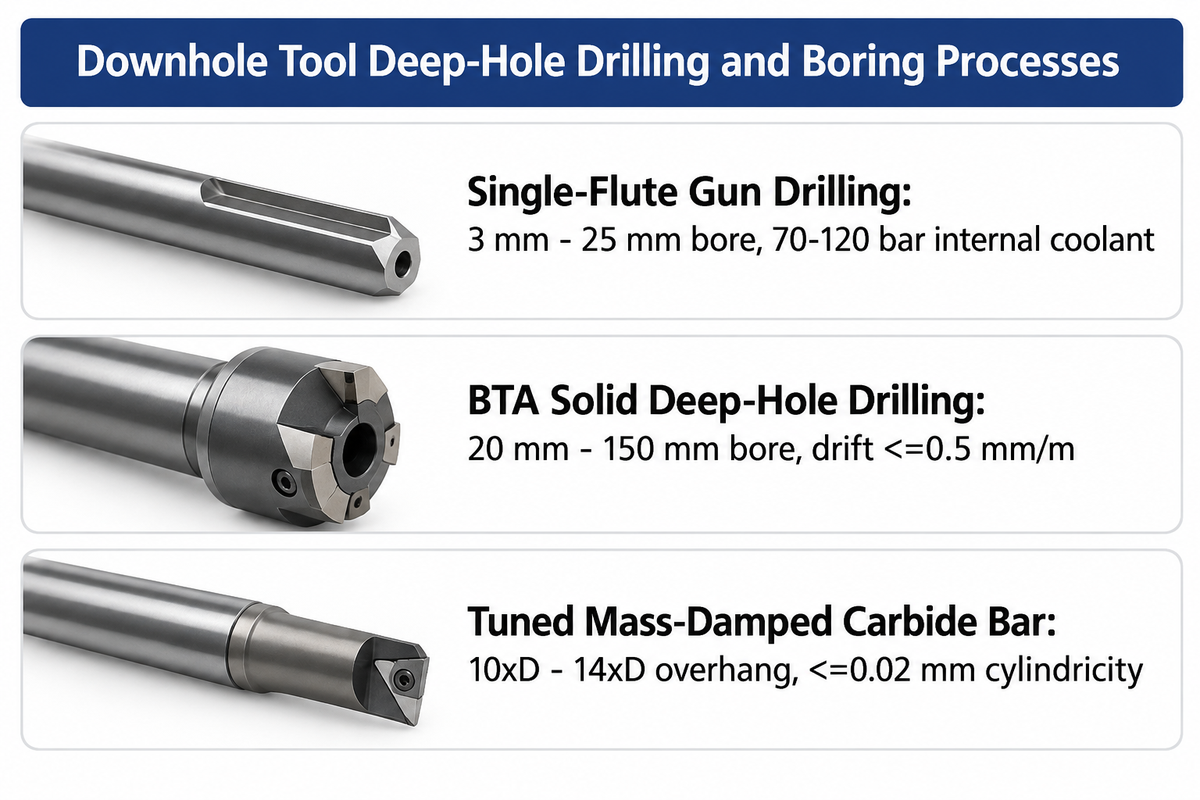
Utilizing advanced cnc turn-mill platforms enables shops to finish non-magnetic MWD collars in one setup. Multi-axis cnc milling carves deep resistivity antenna pockets along the collar. Counter-rotating BTA drills boost deep-hole productivity by fourfold compared to regular twist drills. Each telemetry pocket must be exact specifications for wall eccentricity. Custom machining fixtures hold 9-meter bars without bending. Combining deep-hole boring and 5-axis cnc profiling shortens the time required to produce stabilizers.
drill drilling advances the bit by a small incremental amount and then returns the drill string to its original position. In between these movements, above the bit, the bottom-hole assembly (BHA) houses directional steering sensors, telemetry mud pulsers and stabilizers. Standard ferromagnetic alloy steels blind the sensors. Therefore, magnetic survey instruments in MWD and LWD tools read the earth’s magnetic field to calculate wellbore inclination and azimuth. MWD housings and non-magnetic drill collars are machined from high-Nitrogen Chromium-Manganese (Cr-Mn) austenitic stainless steels or Copper-Beryllium alloys, that are cold-worked to yield strengths above 758 MPa (110 ksi).
Machining a 9-meter non-magnetic drill collar or MWD housing presents two severe metalworking hurdles: extreme length-to-diameter (L/D) internal boring ratios and complex multi-cavity exterior pockets. An MWD collar may have a 50 mm central mud bore along its entire 9,000 mm length (an L/D ratio of 180xD), as well as three off-center 12 mm wiring holes and numerous irregular exterior pockets for gamma-ray and resistivity antennas.
| Deep-Hole Process | Optimal Bore Diameter Range | Max Practical L/D Ratio | Coolant Delivery and Chip Evacuation | Typical Centerline Drift (per 1,000 mm) | Primary Oilfield Use Case |
|---|---|---|---|---|---|
| Single-Flute Gun Drilling | 3 mm – 25 mm | Up to 100xD – 150xD | Internal high-pressure coolant (70–120 bar); external V-flute chip return | 0.3 – 0.8 mm/m (with part rotation) | Off-center MWD wiring conduits, hydraulic control lines in packers |
| BTA Solid Deep-Hole Drilling | 20 mm – 150 mm | Up to 100xD | External pressurized oil via pressure head; internal chip evacuation through drill tube | <=0.5 mm/m under counter-rotation | Central mud bores in drill collars, heavy-weight drill pipe, pup joints |
| BTA Trepanning (Core Recovery) | 65 mm – 300 mm | Up to 60xD | External coolant supply; internal chip flow around solid central core bar | 0.4 – 0.7 mm/m | Large-bore Inconel 718 and Titanium mandrels (saves solid alloy core) |
| Tuned Mass-Damped Carbide Boring Bar | 25 mm – 250 mm | 10xD – 14xD overhang | Internal through-bar nozzle directed at insert cutting edge | <=0.02 mm cylindricity over stroke | Stepped MWD electronics seal bores, valve body cavities, packer sleeves |
As documented in Modern Machine Shop’s deep-hole drilling and boring analysis, BTA (Boring and Trepanning Association) systems achieve four to six times higher penetration rates than gun drills on central bores larger than 20 mm. Because BTA systems pump clean cutting oil around the outside of the drill tube and flush hot chips back through the hollow interior of the tube, the freshly cut bore wall is never scratched by exiting stainless steel chips. To keep centerline drift below 0.5 mm per 1,000 mm of bore length, shops rotate both the drill collar (in opposite counter-rotation) and the BTA drill tube while monitoring wall thickness eccentricity in real time with ultrasonic transducers.
While stepping out internal MWD seals with bores from 10xD to 14xD overhang, standard boring bars deflect and resonate with harmonic chatter. Some shops use solid carbide boring bars while others use tuned mass-damped anti-vibration boring bars. The mass damper helps eliminate harmonic frequencies by using a heavy tungsten-alloy mass mounted in an elastomeric bushing at the bar head. Once the internal bore passes ultrasonic inspection, the collar moves to a 4-axis or 5-axis turn-mill center to mill the spiral stabilizer blades or exterior sensor pockets in a single clamped setup.
How does multi-tasking machining reduce cost on drilling equipment?
mill machining centers reduces production costs at drilling equipment by combining heavy OD turning, API rotary thread chasing, off-center gun drilling, and 5-axis spiral flute milling in a single clamping setup. Eliminating four separate machine setups and reducing crane handling bottlenecks on 2-ton drill collars removes runout errors across MWD sensor pockets.
Single-setup turn-mill processing reduces work-in-process time by 40% to 60%, and ensures the external directional orientation slots align concentrically with the internal BTA mud bore and rotary shouldered thread within ±0.015 mm.
4. Machining API 6A Valve Bodies, Blowout Preventers (BOP), and High-Pressure Flanges
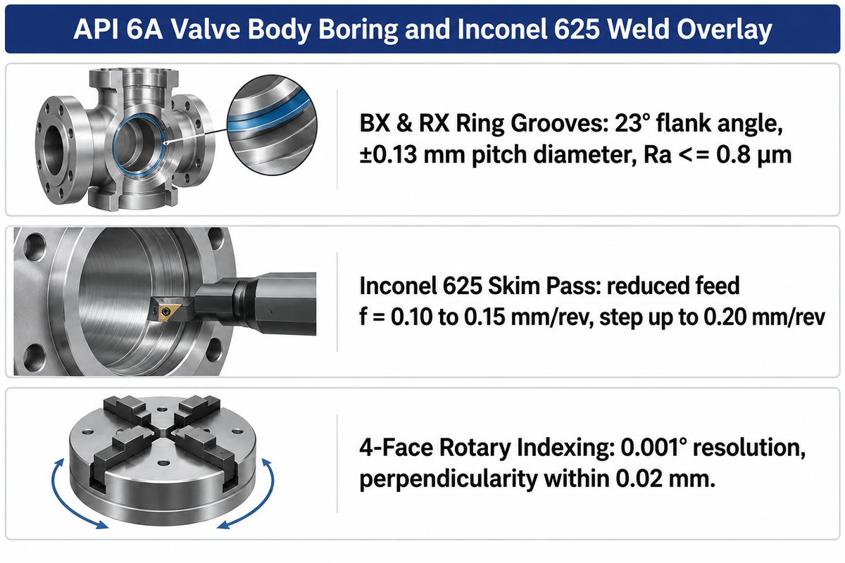
Disciplined machining processes are required to bore intersecting cavities in 15,000-psi forged valve blocks. Integrated cnc solutions enable 23-degree BX ring groove cutting with a U-axis facing head. Meeting demands of oil and gas wellheads requires a metal-to-metal seal with zero leakage. Gas industry cnc machining cells use a rotary table to index a 10-ton BOP forging. Precision machining for the oil wellhead market also calls for uneven rough-turning of Inconel 625 weld overlays.
At the surface wellhead and on the deepwater seabed, API 6A gate valves, Christmas tree blocks, and API 16A blowout preventers (BOPs) serve as the final physical barrier against uncontrolled hydrocarbon blowouts. Unlike cylindrical downhole tubulars, valve bodies and BOP blocks start as massive, asymmetric closed-die forgings of AISI 4130, 4140, or F6NM martensitic stainless steel weighing anywhere from 500 kg to over 12,000 kg.
Machining an API 6A slab gate valve body requires precise geometric alignment across three intersecting axes: the horizontal flow-run bore, the vertical bonnet and gate cavity, and the opposing seat pockets. In addition, every flanged outlet must be turned with an API 6A Type 6B or 6BX ring-joint gasket groove (using RX or BX octagonal/oval metal seal rings). According to API Spec 6A, BX and RX ring grooves must hold a 23° flank angle, a pitch diameter tolerance of ±0.13 mm (±0.005 in.), and a mirror-like sealing surface finish of Ra <= 0.8 µm (32 µin.) so the soft iron or Inconel ring gasket crushes into a zero-leakage metal-to-metal seal.
It’s cost prohibitive to forge the entire 5-ton valve body from solid Inconel 625 to manufacture a body for a sour-gas well that contains hydrogen sulfide. Typically, manufacturers forge the outer pressure housing from high-strength AISI 4130 low-alloy steel, roughly machine the internal bores and ring grooves, and then add a 5 to 7 mm thick Inconel 625 (UNS N06625) weld overlay (CRA cladding) via automated hot-wire TIG welding to the wetted seal pockets and ring grooves. The part then returns to the CNC horizontal boring mill to machine the wavy, work-hardened Inconel 625 weld beads down to a finished cladding thickness of 3.0 to 5.0 mm.
Raw Inconel 625 weld overlay in a deep valve seat pocket is difficult to machine because the raw weld overlay has an irregular, interrupted surface with slag inclusions and hardness spikes. Information in valve pocket Inconel 625 overlay boring discussions indicates that performing this operation on a horizontal boring mill requires four disciplined shop practices:
- Use a Box-Way Horizontal Boring Mill with a CNC Contouring Facing Head: A built-in U-axis radial facing slide on a rigid boring spindle allows the machine to turn internal seat pockets, back-spotface bolt holes, and interpolate 23° BX ring grooves while the valve forging is supported in the B-axis rotary table.
- Select Tough PVD-Coated Sub-Micron Carbide with a 45° Lead Angle or Round Insert: Don’t go after raw weld beads using a fragile 90° square shoulder insert. Use a 45° lead angle or a round button insert (RCMT / RNGN) instead to gradually thin the chip load and strengthen the corner against the impact of interrupted weld-bead strikes.
- Halve the Feed Rate on the First Interrupted Skim Pass: Run the initial crust-breaking pass at Vc = 25 to 30 m/min and a reduced feed of f = 0.10 to 0.15 mm/rev until a continuous cylindrical surface is established, then step up to 0.20 mm/rev for subsequent passes.
- Single-Setup 4-Face Indexing: Clamp the valve body once on a high-precision CNC rotary table (0.001° indexing resolution) to rough and finish all four flange faces and intersecting bores in one coordinate system, keeping gate-slot-to-stem-bore perpendicularity within 0.02 mm. Maintain gate-slot-to-stem-bore perpendicularity of 0.02 mm or less while doing so.
How can CNC machining improve offshore and subsea operations?
CNC machining improves offshore and subsea operations by holding micron-level sealing finishes (Ra <= 0.8 µm) on metal-to-metal BX ring grooves and Inconel 625 clad valve seat pockets that must operate maintenance-free on the ocean floor for 25 years. Multi-axis horizontal boring along with turn-mill centers help eliminate angular misalignment between intersecting bores in subsea Christmas trees and manifolds.
When equipment rests at 3,000 meters water depth with 15,000 psi wellbore pressure, even a 0.05 mm concentricity error on a subsea connector hub can cause seal extrusion. High-rigidity CNC machining ensures complete dimensional interchangeability for remotely operated vehicle (ROV) intervention tools.
5. Machining Superalloys and CRAs for NACE MR0175 Sour Gas Service: Inconel 718, 625, and Super Duplex
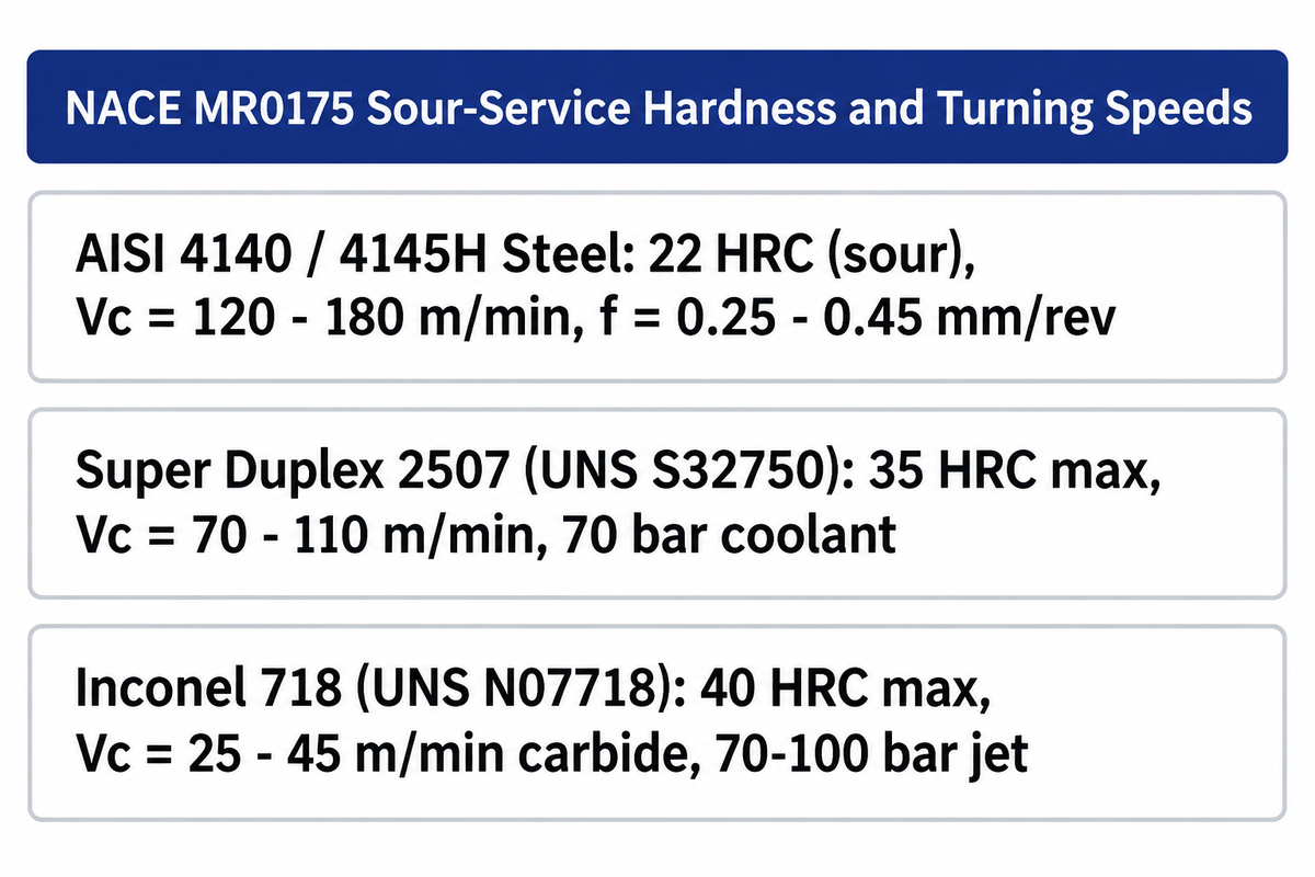
High-pressure cnc machining for oil sour-service completions control work hardening in nickel alloys. Flow controllers, complex geometries, trap heat at the cutting edge. All pressure containing critical parts must remain below NACE MR0175 hardness limits. Due to the oil and gas industry operates in corrosive hydrogen sulfide reservoirs, mirror finish surface finishes are required on seal bores. Qualifying cnc machining services for oil superalloys requires a 70 bar through spindle coolant.
Reservoirs categorized as “sour service” contain toxic, corrosive hydrogen sulfide (H2S) gas alongside carbon dioxide and chloride brines. In the presence of wet H2S, atomic hydrogen diffuses into stressed steel grain boundaries, causing brittle catastrophic fracture known as Sulfide Stress Cracking (SSC) at stresses far below the alloy’s normal yield point. To prevent SSC disasters, all metallic oilfield components exposed to sour fluids must comply with NACE MR0175 / ISO 15156.
NACE MR0175 imposes strict metallurgical hardness ceilings: carbon and low-alloy steels (like AISI 4130 and 4140) must not exceed 22 HRC (237 HBW); Super Duplex 2507 (UNS S32750) is capped at 35 HRC; and precipitation-hardened nickel superalloy Inconel 718 (UNS N07718, oilfield grade) is limited to 40 HRC (compared to 44–46 HRC in aerospace). Why does a metallurgical hardness standard matter to a CNC machinist? Because improper cutting parameters induce severe plastic deformation and thermal white-layer formation on the machined surface, driving skin micro-hardness 4 to 8 HRC points above the bulk core hardness and rendering a $30,000 forging non-compliant with NACE MR0175.
| Material Grade and UNS | NACE MR0175 Max Hardness | Carbide Turning Speed (Vc) | Ceramic Roughing Speed (Vc) | Feed Rate (f, Turning) | Depth of Cut (ap, Rough / Finish) | Coolant Pressure and Tooling Strategy |
|---|---|---|---|---|---|---|
| AISI 4140 / 4145H Q&T Alloy Steel | 22 HRC (sour) / 32 HRC (sweet drill collar) | 120 – 180 m/min | Not applicable (CVD carbide preferred) | 0.25 – 0.45 mm/rev | 2.5 – 6.0 mm / 0.4 – 1.0 mm | 20–40 bar flood; CVD TiCN/Al2O3 coated carbide |
| Super Duplex 2507 (UNS S32750) | 35 HRC (PREN >= 42) | 70 – 110 m/min | Not applicable (chemical reactivity) | 0.20 – 0.35 mm/rev | 2.0 – 4.0 mm / 0.3 – 0.8 mm | 70 bar through-tool; tough PVD TiAlN positive-rake carbide |
| Inconel 625 Clad / Solid (UNS N06625) | 35 HRC (annealed / overlay) | 25 – 40 m/min | 150 – 220 m/min (SIALON / whisker) | 0.15 – 0.25 mm/rev | 1.5 – 3.5 mm / 0.25 – 0.5 mm | 70–100 bar high-pressure jet; 45° lead or round insert |
| Inconel 718 Oilfield Grade (UNS N07718) | 40 HRC (solution + aged) | 25 – 45 m/min | 180 – 250 m/min (continuous OD only) | 0.12 – 0.22 mm/rev | 1.0 – 3.0 mm / 0.20 – 0.4 mm | 70–100 bar targeted jet; thin PVD TiAlN / SIALON roughing |
| Titanium Grade 5 (Ti-6Al-4V) | 36 HRC (offshore risers / stress joints) | 45 – 65 m/min | Not applicable (reacts with ceramic) | 0.15 – 0.25 mm/rev | 1.5 – 3.5 mm / 0.25 – 0.5 mm | 70–100 bar high-flow coolant; uncoated H13A / sharp PVD carbide |
When turning heat-resistant superalloys (HRSA) like Inconel 718 and Inconel 625, their low thermal conductivity (11.4 W/m·K, less than one-third of carbon steel) traps 80% of cutting heat directly in the tool edge while the austenitic nickel matrix work-hardens instantly under shear. Based on Sandvik Coromant’s HRSA machining guidelines en Cutting Tool Engineering’s superalloy studies, shops must enforce three counter-intuitive rules:
- Never Take a Light Skim Pass Shallower Than the Work-Hardened Layer: Pas izods of Inconel 718 leave behind a 0.08 to 0.12 mm deep work-hardened skin. If a finishing pass uses ap of 0.05 mm, the cutting tip takes a ride inside that layer, rapidly abrasioning the flank, and leaving tensile stress on the surface. Always use a finishing depth of cut of 0.20 mm or greater with a positive-rake insert.
- Eliminate Depth-of-Cut Notch Wear by Varying ap and Using 45° or Round Inserts: Very rapid V-shaped notch wear occurs at the depth-of-cut line. Here, the insert is making contact with the uncut work-hardened outer skin of the part. One way to alleviate notch wear is to use inserts with a 45° lead angle or a round insert which will thin the chip at the boundary. Using a 45° lead angle or round insert thins the chip at the boundary, and programming successive roughing passes with stepped depths of cut (e.g., 2.5 mm, then 2.1 mm, then 1.8 mm) moves the wear point along the cutting edge.
- Deploy 70 to 100 Bar Through-Spindle Coolant: Standard 7-bar flood coolant evaporates into a steam barrier before reaching the 1,100°C Inconel shear zone. High-pressure coolant at 70 to 100 bar (1,000 to 1,450 psi) aimed through the toolholder overhang shoots a high-velocity hydraulic wedge underneath the chip, lowering insert temperature by 30% and mechanically snapping stringy nickel ribbons into short, evacuable segments. This reduces the temperature of the insert by 30% and mechanically breaks up stringy nickel ribbons into shorter segments that can be evacuated. (Note: SIALON and whisker-reinforced ceramic roughing speeds of 180 to 250 m/min, strictly applied to the outer-diameter continuous roughing of forged Inconel 718, must not be applied to final thread finishing passes of API where ceramic edges can chip against sharp thread roots, thereby introducing a potential safety hazard.)
What materials can CNC machines handle for energy industry parts?
The latest high-end CNC machines can cut through the full range of alloys in the energy sector, including quenched-and-tempered low-alloy steels (AISI 4130, 4140, 4145H and 4330V), martensitic and precipitation-hardening stainless steels (13Cr, F6NM and 17-4 PH), duplex and super duplex (2205 and 2507), nickel-based superalloys (Inconel 718 and Inconel 625), Monel K-500, and Cr-Mn drill collar alloys.
Depending on the alloy, reliable processing of these exotic materials sometimes requires geared headstocks that deliver full torque at 200 RPM or below, a rigid cast-iron box-way frame that absorbs cutting shock, and 70 bar through spindle coolant to prevent work hardening and thermal cracking.
6. Calculating Thread Lead Error, Clamping Torque, and the 4-Stage API Threading Protocol
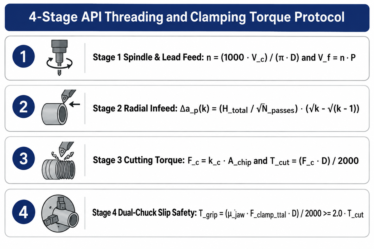
All pipe threading shops in oil and gas industry faces suffer severe insert nose wear when pass depths aren’t decremented properly. Quantitative process engineering in machining for oil and gas eliminates trial-and-error thread chasing. Threading complex parts, like step-tapered premium connections, requires radial constant-chip-area in-feed schedules. Downhole tools have to survive extreme conditions where axial string tension exceeds 400 tons. Selecting high-performance PVD carbide threading inserts avoids root chipping.
Single-point chasing a coarse 5-TPI (BTC) or 4-TPI API 7-2 rotary connection on tough alloy casing generates intense radial and tangential cutting forces. If the programmer divides the thread depth into equal radial passes or miscalculates chuck grip torque, the insert nose chips on the final passes, the pipe slips rotationally in the jaws, or cumulative lead error exceeds the ±0.025 mm per 25.4 mm API ceiling. To eliminate thread scrap, our applications engineers developed the 4-Stage API Threading & Sour-Service Machining Protocol.
4-Stage API Threading & Sour-Service Machining Protocol Equations:
- Stage 1, Spindle RPM & Synchronized Lead Feed:
n = (1000 · V_c) / (π · D)enV_f = n · P
waarnis spindle speed (RPM),V_cis cutting speed (m/min),Dis pipe pitch diameter (mm),Pis thread pitch (mm/rev), andV_fis Z-axis feed rate (mm/min). - Stage 2 (Constant-Chip-Area Radial Pass Depth (Modified Flank Infeed 1°) 3°):
Δa_p(k) = (H_total / √N_passes) · (√k - √(k - 1))
waarH_totalis total radial thread profile depth (mm),N_passesis total roughing passes, andkis the current pass index (k = 1, 2, …, N). - Stage 3, Tangential Cutting Force & Torque Load:
F_c = k_c · A_chipenT_cut = (F_c · D) / 2000
waark_cis specific cutting force (N/mm²),A_chipis single-pass chip cross-sectional area (mm²), andT_cutis cutting torque (Nm). - Stage 4, Dual-Chuck Slip Resistance Safety Margin:
T_grip = (μ_jaw · F_clamp_total · D) / 2000 >= 2.0 · T_cut
waarμ_jawis serrated hard-jaw friction coefficient (0.25–0.35) andF_clamp_totalis combined front-and-rear radial chuck clamping force (N).
Let’s walk through a complete worked numerical example using standard CNC turning and threading formulas. Suppose your shop is threading a 9-5/8 in. (244.5 mm OD) API 5CT L80 / P110 carbon steel casing pipe with a 5-TPI (P = 5.08 mm) API Buttress (BTC) external pin thread (Htotal = 1.575 mm total radial thread depth plus cresting allowance = 1.75 mm total infeed) using a full-profile PVD-coated carbide threading insert at a recommended cutting speed of Vc = 110 m/min:
Step 1 (Spindle Speed and Z-Axis Feed Rate):
n = (1000 × 110) / (3.1416 × 244.5) = 143.2 RPM → Program n = 143 RPM
V_f = 143 RPM × 5.08 mm/rev = 726.4 mm/min
At 726.4 mm/min longitudinal feed, the CNC servo drive must accelerate to full synchronized speed within the chamfer entry clearance before engaging the first thread turn. (Note: This worked 10-pass constant-chip-area calculation of n = 143 RPM and Vf = 726.4 mm/min is calibrated for 9-5/8 in. L80/P110 carbon steel casing at Vc = 110 m/min and must be derated to 30–45 RPM when threading 13Cr or Super Duplex CRA tubulars.)
Step 2 (10-Pass Constant-Chip-Area Infeed Schedule):
Why can’t you simply take 10 equal passes of 0.175 mm each? Because a V-shaped or trapezoidal thread insert engages a wider and wider flank length as it plunges deeper into the groove. An equal 0.175 mm depth on Pass 10 removes nearly 10 times more metal volume than 0.175 mm on Pass 1, shattering the insert corner. Using the constant-chip-area formula with Htotal = 1.75 mm and N = 10 passes at a 2° modified flank infeed angle:
- Pass 1 (k=1): Δ ap(1) = (1.75 / √10) × 1.000 = 0.553 mm (Cumulative depth: 0.553 mm)
- Pass 2 (k=2): Δ ap(2) = 0.553 × (√2 – 1) = 0.229 mm (Cumulative depth: 0.782 mm)
- Pass 3 (k=3): Δ ap(3) = 0.553 × (√3 – √2) = 0.176 mm (Cumulative depth: 0.958 mm)
- Passes 4 to 9: Progressively decrementing from 0.148 mm down to 0.095 mm
- Pass 10 (k=10): Δ ap(10) = 0.553 × (√10 – √9) = 0.089 mm + one final 0.05 mm full-profile spring/cresting pass to wipe the thread flanks and deburr the crest to Ra ≤ 1.6 μ m.
Step 3 & 4 (Clamping Torque Verification):
During the heaviest roughing pass (Achip ≈ 0.65 mm²) in P110 steel (kc ≈ 2,400 N/mm²), tangential cutting force reaches Fc = 1,560 N, generating a cutting torque of Tcut = (1,560 × 244.5) / 2000 = 190.7 Nm. When threading heavier API 7-2 NC50 drill collars or rough-turning 6 mm deep shoulders, cutting torque spikes above 1,800 Nm. Dual four-jaw hydraulic/pneumatic chucks applying 80 kN total radial clamping force (μjaw = 0.30) generate Tgrip = (0.30 × 80,000 × 244.5) / 2000 = 2,934 Nm of slip resistance, maintaining a safe ≥ 1.6–2.0× dynamic factor without crushing thin-wall casing.
How does CNC machining reduce production costs?
Automating constant chip-area multi-pass thread chasing with CNC machining reduces costs associated with oilfield production by eliminating errors associated with taper-attachment setups and doubling the life of carbide inserts from 3 joints per corner to over 12 joints per corner. Electronic C-axis thread repair macros allow shops to salvage worn $4,000 drill pipe tool joints in 8 minutes by removing 0.20 mm of fatigued thread flank.
In addition, high-pressure 70-bar coolant systems and rigid box-way beds allow machinists to rough-turn high-alloy forgings at 35% higher metal removal rates while holding first-pass API gauge standoff yields above 99.2%.
7. Comparing Machine Tool Architectures: Double-Chuck Pipe Lathes vs Horizontal Boring Mills vs 5-Axis Turn-Mill Centers
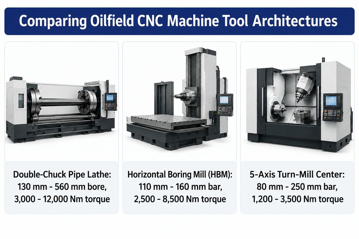
Selecting capital machining equipment depends on whether your part spectrum is tubular or prismatic. Turnkey engineering services for oil and gas plants pair big-bore lathes with horizontal boring mills. Modern multi-tasking cnc machining has revolutionized how shops transition from 3-assig roughing to simultaneous 5-axis cnc machining. Upgrading from 3-axis to 5-axis contouring eliminates three intermediate fixture setups on PDC drill bits. Standardized manufacturing processes keep spindle utilization above 85%.
Equipping an oilfield manufacturing cell means aligning machine kinematics and guideway structure with the primary component envelope. A job shop that buys a high-speed linear-guideway vertical machining center to roughly bore forged Inconel-clad BOP blocks will burn through inserts and destroy bearings in a few weeks. Alternatively, putting simple API 5CT casing couplings on a $1.2 million 5-axis turn-mill center gives uncompetitive machine rates.
In heavy oil and gas manufacturing, three machine architectures form the backbone of production: Double-Chuck Big-Bore CNC Pipe Threading Lathes , Table-Type CNC Horizontal Boring Mills (HBM), and 5-Axis Multi-Tasking Turn-Mill Centers .
| Engineering Parameter | Double-Chuck CNC Pipe Threading Lathe | Table-Type Horizontal Boring Mill (HBM) | 5-Axis Multi-Tasking Turn-Mill Center |
|---|---|---|---|
| Primary Workpiece Geometry | Long cylindrical pipes, casing, tubing, drill collars (3–12 m length) | Prismatic/blocky forgings: API 6A gate valves, BOPs, Christmas trees, manifolds | Complex cylindrical + prismatic: MWD housings, spiral stabilizers, PDC bits |
| Spindle Bore / Work Envelope | 130 mm – 560 mm hollow through-bore; unlimited pass-through length | 110 mm – 160 mm extendable boring bar; rotary table up to 2,000 × 2,500 mm | 80 mm – 250 mm bar capacity; closed bed length 1,500 – 4,000 mm |
| Low-RPM Spindle Torque | 3,000 – 12,000 Nm (2-speed or 4-speed geared headstock) | 2,500 – 8,500 Nm (heavy geared boring ram + U-axis facing head) | 1,200 – 3,500 Nm (built-in integral electro-spindle + B-axis milling head) |
| Guideway Construction | 755 – 1,100 mm integral induction-hardened cast-iron box ways (>HRC 52) | Heavy hardened box ways with Turcite-B damping pads (5–15 ton payload) | Heavy roller linear guideways or hybrid box/linear ways |
| Single-Setup Consolidation | Specialized for OD/ID turning, facing, and high-torque API taper threading | 4-sided indexing + contour boring + flange ring-groove facing in 1 clamping | Full 5-axis simultaneous milling + turning + off-center gun drilling in 1 setup |
| Typical Hourly Shop Rate & Payback | $85 – $130/hr; fastest ROI (14–22 months) on OCTG and drill stem batches | $140 – $220/hr; definitive choice for 1–15 ton high-pressure valve bodies | $180 – $300/hr; justified for high-complexity MWD/LWD and aerospace-grade CRA parts |
One of the most important structural decisions when ordering equipment for oilfield roughing is Induction-Hardened Box Ways vs. Linear Roller Guideways. Linear guideways can achieve rapid 40 m/min traverses with aluminum or small steel components. However, when 6 mm interrupted roughing passes are taken on a forged 4145H drill collar or when a wavy Inconel 625 weld is being bored in a valve pocket, very high cutting forces are generated, and releases happen hundreds of times a minute. A cast-iron box way (like a 755 mm wide heavy lathe bed induction hardened above HRC 52 and mated with Turcite-B sliding surfaces) provides a large contact area which damps low frequency (vibrations) significantly better than a point-contact roller bearing. To learn more about turning centers, read our articles on CNC industrial CNC lathe machines en draaien en tight tolerance machining.
What types of CNC machines are used in oil and gas manufacturing?
Oil and gas manufacturing relies on five core CNC machine types: double-chuck big-bore CNC pipe threading lathes for OCTG casing and drill pipe tool joints; table-type horizontal boring mills (HBMs) with U-axis facing heads for multi-ton API 6A gate valves and BOP blocks; BTA and gun deep-hole drilling machines for 100xD drill collar bores; vertical turret lathes (VTLs) for large pipeline flanges; and 5-axis turn-mill centers for MWD housings and PDC drill bits.
Most high output oilfield machine shops use a hybrid cellular layout, combining cost effective double-chuck box-way pipe lathes for dedicated API thread chasing with multi-axis horizontal boring and turn-mill centers for prismatic cavities.
8. Quality Assurance, API Thread Gauging, and Shop Troubleshooting (Galling, Chatter, and Drift)
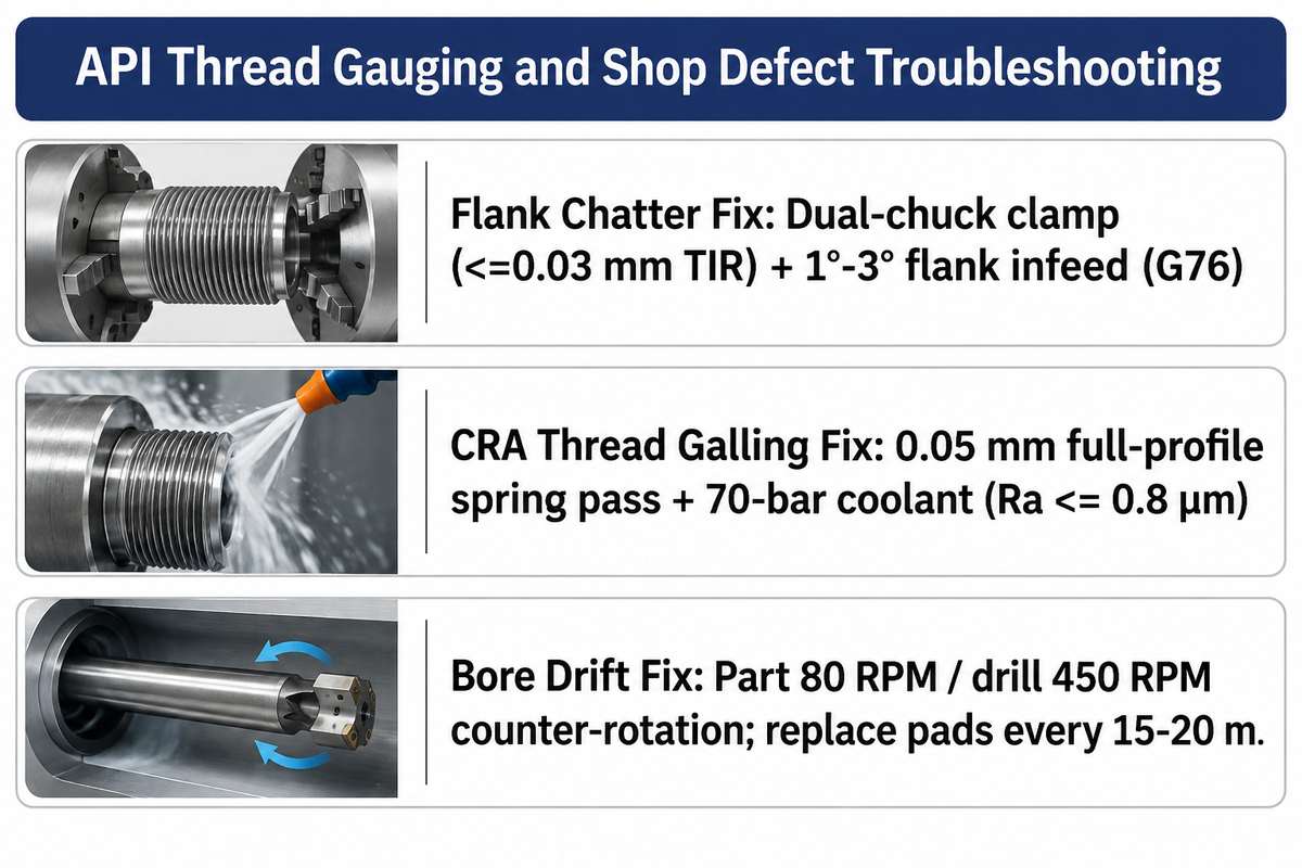
Quality assurance for demanding applications in subsea completions begins in a 20°C temperature controlled gauge room. Diverse machining applications require both master plug standoff checks and optical thread contour scanning. Every shipment of precision parts includes magnetic particle or liquid penetrant inspection reports. Closed-loop cnc technology compensates for thermal growth of ballscrews in turning operations. 5-axis CMM probing is required for checking intricate components like mud pulse valves.
In out-of-spec thread situations, high-pressure gas can leak out or Cold Welding can occur in the drilling rig floor. Quality assurance for API Spec 5B, API Spec 7-2 and API Spec Q1 requires physical standoff gauging, coupled with single element thread metrology and non-destructive testing (NDT).
Every API thread connection is gauged with a pair of hardened, ground Working Plug and Ring Gauges that have been calibrated against API Master Gauges in a temperature-controlled metrology laboratory, which is stabilized at 20°C ± 1°C (68°F ± 2°F). When the gauges are screwed onto or plugged into the associated box coupling, the distance between the gauge reference plane and the pipe end face or torque shoulder is measured, and called Standoff (S value).
Standoff is used to verify combined functional fit of pitch diameter, taper, lead, and flank angle. However, because a pitch diameter error can mask a dangerous taper error in a functional ring gauge check, API 5B and 7-2 also require direct inspection of: Thus, as per API 5B and 7-2, the following taper checks are also required:
- Thread Taper: Measured with an external or internal dial caliper gauge at 1-inch (25.4 mm) intervals along the full thread length (holding 1:16 or 1:6 taper within +0.003 / -0.001 in./in.).
- Thread Lead and Height: Total thread lengths and heights of 1-inch lead-in lengths were checked with a calibrated zero-set lead gauge and thread depth indicator.
- Optical Profile and Non-Destructive Testing (NDT): Thread root radii and flank angles are scanned using optical contour projectors. Ferromagnetic steels are then inspected by wet fluorescent MPI, and non magnetic stainless and Inconel alloys are inspected by LPT to ensure there are no micro-cracks.
| Shop Defect / Failure Mode | Observed Metrology / Rig Symptom | Primary Machining Root Cause | Quantitative Corrective Action on the CNC Machine |
|---|---|---|---|
| API Thread Flank Chatter Marks | Visible ripple marks on 3°/10° or 30° flanks; fails Ra <= 1.6 µm spec | Pipe whip from single-chuck overhang or radial plunge infeed engaging both flanks | Clamp pipe in both front and rear chucks (<=0.03 mm TIR); switch from radial (G92) to 1°–3° modified flank infeed (G76) |
| CRA / 13Cr / Duplex Thread Galling | Threads seize and cold-weld during power-tong make-up on rig | Torn flank finish (Ra > 3.2 µm) + work-hardened ridges from dull insert | Add dedicated 0.05 mm full-profile cermet/PVD spring pass with 70-bar coolant to hold Ra <= 0.8 µm; apply phosphate/copper coat |
| Deep-Hole Bore Centerline Drift | Ultrasonic wall thickness varies >1.5 mm on 9 m MWD drill collar | Stationary workpiece gun/BTA drilling or worn guide pads | Enable workpiece-and-tool counter-rotation (part 80 RPM / drill 450 RPM); replace BTA wear pads every 15–20 m of bore |
| Inconel 718 Depth-of-Cut Notch Wear | Deep V-groove chips out insert edge after 6 minutes; surface >40 HRC | 90° lead angle entering work-hardened scale at constant depth of cut | Switch to 45° lead angle or round insert; step radial ap across passes (2.5 / 2.1 / 1.7 mm); apply 80-bar jet coolant |
| API 6A BX Ring Groove Pressure Leak | Hydrostatic test leaks at 15,000 psi on gate valve flange | 23° groove flank angular error or tool push-off on Inconel 625 cladding | Use U-axis contouring facing head with rigid carbide cartridge; run two zero-offset spring passes to hold Ra <= 0.8 µm |
Why is precision engineering critical in the oil and gas industry?
Precision engineering is critical in the oil and gas industry because downhole strings and subsea wellheads contain explosive hydrocarbons at 10,000 to 20,000 psi and 200°C and are sealed using metal-to-metal interference fits. A 0.03 mm cumulative lead error on an API thread or a 1.6 µm surface scratch on a BX ring groove creates a leak path that can lead to catastrophic well control failures or multi-million dollar offshore rig downtime.
Holding tight tolerances within ±0.013 mm and abiding by NACE MR0175 surface hardness during CNC machining eliminates galling and enables smooth assembly of threaded joints to endure corrosive sour gas fatigue for decades.
9. 2026 HPHT Sour-Service Machining Trends and ANTISHICNC Equipment Procurement Checklist
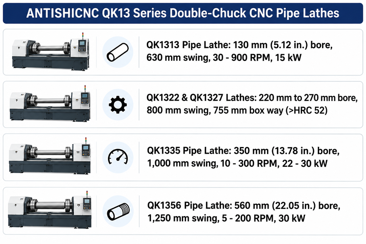
Turnkey application engineering services helps machine shops retool for 20,000-psi ultra deepwater projects. Clamping large components such as 560 mm conductor pipe requires a synchronized front and back hydraulic four jaw chuck. The heaviest box way precision manufacturing solves the toughest engineering challenges in thick-wall CRA pipe threading. For global oil and gas industries, every ANTISHICNC lathe is made to produce oilfield equipment that withstand extreme conditions offshore.
Why is demand for heavy oilfield machining rising while conventional shallow-well drilling plateaus? The decisive industry driver in 2026 is the global shift toward Ultra-Deepwater High-Pressure/High-Temperature (HPHT) fields (rated to 20,000 psi and 177°C, 204°C) and high-H2S sour gas reservoirs, alongside the repurposing of depleted offshore wells for carbon capture and storage (CCS). As documented in Offshore Magazine’s 20,000-psi HPHT subsea wellhead engineering coverage, operating at 20,000 psi forces equipment designers to increase forging wall thicknesses by 30% to 45% and replace standard carbon steels with solid Inconel 718, Super Duplex 2507, or thick Inconel 625 weld overlays.
For machine shop owners and equipment specifiers, this shift in metallurgy changes the game on the shop floor. Light-duty, belt-driven CNC lathes used for high-RPM aluminum and mild steel simply stall out when chasing a 4-TPI rotary connection on a 350 mm thick wall CRA pipe. The modern oilfield shop is upgrading to heavy-duty box-way double-chuck pipe threading lathes with high-torque multi-speed gearboxes, 70 bar high-pressure coolant pumps, and electronic C-axis thread repair software.
To address heavy-duty requirements on the full range of API tubing, casing, and drill collars, SHANGHAI ANTS Machine Equipment (ANTISHICNC) manufactures the QK13 series of double-chuck CNC pipe threading lathes, along with heavy-duty TPX and TK horizontal boring mills. Below is the engineering specification matrix for the ANTISHICNC QK13 series pipe threading platform.
| ANTISHICNC Model | Spindle Through-Bore Diameter | Max Swing Over Bed / Carriage | Spindle Speed Range & Gear Steps | Main Spindle Motor Power | Hardened Box-Way Bed Width | Target Oilfield Component Spectrum |
|---|---|---|---|---|---|---|
| QK1313 CNC Pipe Lathe | 130 mm (5.12 in.) | 630 mm / 350 mm | 30 – 900 RPM (stepless / geared) | 15 kW high-torque AC | 550 – 600 mm integral cast iron | 2-3/8″ to 4-1/2″ API production tubing, pup joints, small drill subs |
| QK1322 CNC Pipe Lathe | 220 mm (8.66 in.) | 800 mm / 460 mm | 20 – 450 RPM (4-step geared) | 15 – 18.5 kW | 755 mm hardened box way (>HRC 52) | 4-1/2″ to 7″ API 5CT casing, NC38–NC50 drill pipe tool joints, drill collars |
| QK1327 CNC Pipe Lathe | 270 mm (10.63 in.) | 800 mm / 460 mm | 20 – 450 RPM (4-step geared) | 18.5 – 22 kW | 755 mm hardened box way (>HRC 52) | 7″ to 9-5/8″ BTC/LTC casing, non-magnetic MWD housings, mud motor stators |
| QK1335 CNC Pipe Lathe | 350 mm (13.78 in.) | 1,000 mm / 630 mm | 10 – 300 RPM (high-torque geared) | 22 – 30 kW | 755 mm hardened box way (>HRC 52) | 9-5/8″ to 13-3/8″ intermediate casing, downhole packer bodies, casing hangers |
| QK1356 CNC Pipe Lathe | 560 mm (22.05 in.) | 1,250 mm / 840 mm | 5 – 200 RPM (heavy 4-step geared) | 30 kW heavy duty | 755 – 1,100 mm heavy box way | 16″ to 20″ conductor casing, offshore riser connectors, large forged spools |
Engineering Boundary Note: ANTISHICNC QK1313-QK1356 spindle bore capacities (130 to 560 mm) represent maximum through-spindle clear bar or pipe diameters; actual clamped outer diameter is governed by the selected front and rear pneumatic or hydraulic four-jaw chuck jaw stroke and rear spider guide bushing size.
7-Point Oilfield CNC Equipment RFQ & Factory Acceptance Test (FAT) Checklist:
Prior to issuing a purchase order for a CNC pipe threading lathe or horizontal boring mills for oil and gas component manufacturing, you must verify these seven technical requirements with your machine builder:
- Clear Spindle Bore vs. Coupling Upsets: Size the spindle bore on the lathe headstock at least 15-25 mm larger than the maximum external upset (EU) diameter or the tool joint box OD of the pipe that passes through the headstock. DO NOT base this on the nominal pipe body OD.
- Front-and-Rear Chuck Coaxiality (FAT Requirement): Require a Factory Acceptance Test certificate to prove the front and rear chucks are dialed coaxially to <=0.025 mm TIR across a ground test bar of the full headstock length.
- Low-Speed Geared Torque Curve: Verify that the headstock incorporates a mechanical 2-speed or 4-speed gearbox capable of delivering full kW power and >=3,000 Nm torque at 30 to 80 RPM for threading large-diameter Super Duplex and Inconel connections.
- Electronic Thread Repair (Teach-In) Software: If your facility performs any MRO on oilfield equipment, confirm the Fanuc 0i-TF or Siemens 828D control has the electronic thread repair re-chasing macro and high resolution C axis spindle encoder.
- Outboard Pipe Support Stand Integration: For any pipe longer than 3 meters, provide heavy duty, height adjustable, outboard roller steady stands to prevent pipe whip from the rear of the pipe creating torsional vibration in the rear chuck.
- 70-Bar High-Pressure Coolant & Chip Conveyor: When machining Inconel 718, 625, or Duplex stainless steels, specify a 70 bar through-spindle/through turret coolant pump, a hinged chip conveyor, and a dual 10 micron bag filter.
- Sample API Thread Gauging Sign-Off: Have the manufacturer cut a sample API 5B BTC or API 7-2 NC connection during FAT and verify thread standoff (S value), taper, and lead using calibrated working ring and plug gauges before shipping. Visit the full range of ANTISHICNC CNC pipe threading lathes and metalworking machines to request a customized machine configuration and cycle-time study for your drawings.
What makes CNC machines ideal for harsh oilfield environments?
CNC machines designed for oilfield manufacturing feature induction-hardened cast-iron box ways (> HRC 52), high-torque geared headstocks (3,000 to 12,000 Nm), synchronized dual four-jaw chucks, and 70-bar high-pressure coolant systems. Heat treatment of the tools hardens them to HRC 52 to 56, enabling them to cut work-hardening superalloys without tool deflection and thermal drift.
Unlike light general-purpose machines, industrial oilfield lathes and horizontal boring mills maintain micron-level repeatability across 24/7 production shifts, ensuring that every machined drill collar, casing coupling, and BOP valve body passes API standoff and hydrostatic pressure tests on the first inspection.
FAQ (Frequently Asked Questions)
Why do oil country pipe threading lathes use two chucks instead of a chuck and tailstock?
Industrial lathes incorporate synchronized front and rear chucks on the same spindle, enabling long tubing and drill pipe to pass directly through the bore of the spindle. Clamping the pipe close to the turret with the front chuck while supporting the protruding rear tube with the rear chuck eliminates overhanging pipe whip, prevents harmonic chatter, and maintains strict API taper concentricity across 12-meter pipe joints. Maintaining strict API taper on long pipe joints is particularly important during pipe threading of oil country casing and tubing which is governed by API Spec 5B.
What is the difference between API 5B and API 7-2 thread machining?
API Spec 5B governs casing, tubing, and line pipe threads, such as Short Round (STC), Long Round (LTC), and Buttress (BTC) connections, designed primarily for hydrostatic pressure containment and axial casing string tension. API Spec 7-2 governs rotary-shouldered connections (NC26-NC50 tool joints) used on drill collars and drill pipes and requires precision machined torque shoulders, to withstand downhole torsional drilling loads.
How does NACE MR0175 affect CNC machining parameters for sour gas components?
NACE MR0175 (ISO 15156) enforces strict maximum hardness ceilings, typically 22 HRC for carbon steels and 35 HRC for Super Duplex stainless steels, to prevent sulfide stress cracking in hydrogen sulfide environments. Machinists must use sharp positive-rake inserts, 70-bar high-pressure coolant, and controlled feed rates to prevent work-hardened surface layers.
When should a shop use BTA drilling instead of gun drilling on oilfield parts?
Gun drilling specializes in drilling small off-center holes less than 20 mm, such as MWD wiring channel holes. For central bore holes of 20 mm and above in drill collars and pup joints, BTA deep-hole drilling helps feed pressurized coolant externally and evacuates chips internally through the drill tube. This helps increase the feed rate by a factor of 4 to 6, improve bore straightness, and maintain the bore straightness integrity of the tool.
How much does oil and gas CNC machining cost for superalloys compared to alloy steel?
Machining oilfield components from nickel-based superalloys like Inconel 718 or Inconel 625 typically costs 3.5 to 6 times more per finished part than machining quenched-and-tempered AISI 4140 or 4145H alloy steel. While 4140 steel turns at surface speeds of 120 to 180 m/min with standard carbide inserts which last 30 to 45 minutes per edge, Inconel 718 turns at surface speeds of 25 to 45 m/min and uses carbide (or SIALON ceramic inserts for roughing) which lasts 8 to 15 minutes per edge. Additionally, components made from Commercially Reactive Alloys (CRA) require the use of a 70 bar high-pressure coolant and filtration, stress relief thermal cycles, liquid penetrant non-destructive testing, and EN 10204 3.1. All these requirements increase cycle time and raise the cost of the component.
Referenties en bronnen
- American Petroleum Institute (API), Specification 5B: Threading, Gauging, and Thread Inspection of Casing, Tubing, and Line Pipe Threads.
- American Petroleum Institute (API), Specification 6A (ISO 10423): Specification for Wellhead and Tree Equipment
- Sandvik Coromant, Machining Heat Resistant Superalloys (HRSA) and Inconel Turning Guidelines.
- Sandvik Coromant, CNC Turning and Single-Point Thread Chasing Formulas and Definitions.
- NACE MR0175 / ISO 15156, Petroleum and Natural Gas Industries: Materials for Use in H2S-Containing Environments
- Modern Machine Shop, Deep-Hole BTA Drilling and Tuned Mass-Damped Boring for Oil and Gas Components.
- US Patent 7,421,931 B2, Anti-Vibration Boring Bar and Dual-Chuck Spindle Synchronization Apparatus.