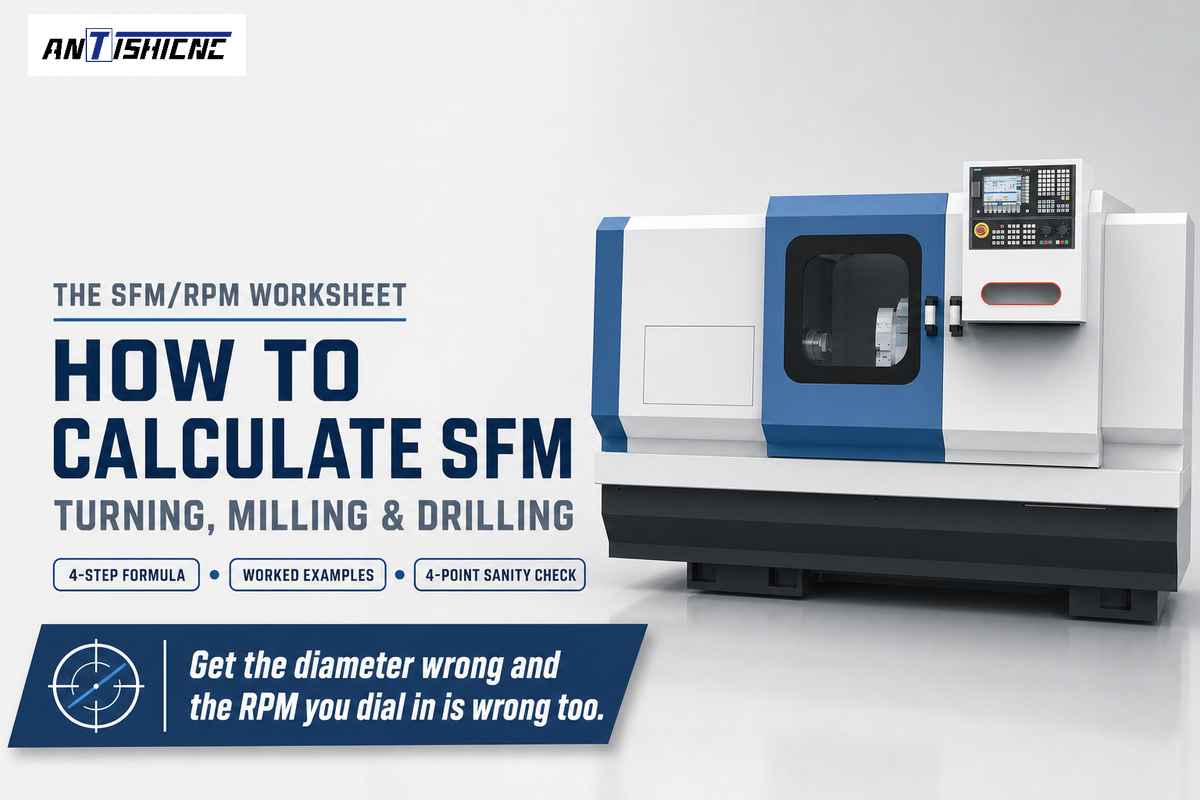
Updated September 2026 CNC lathe programming is the process of converting a drawing into a string
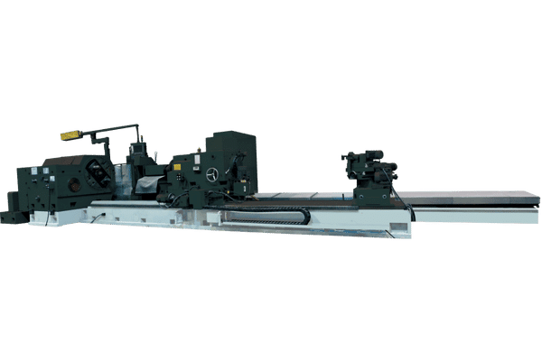
Accomplish distinguished and precise manufacturing results through our state-of-the-art wheelhead lifting, moving cylindrical grinder designed for high-performance manufacturing environments and optimum volume productivity.
MCW and MKW correspond to PLC and CNC grinding machines, respectively, and MCD and MKD to center-fixed grinding machines for heavy parts with great efficiency and simplicity of operation.
Fixed center grinding machinery has a movable wheel head configuration with longitudinal Z-axis motion and cross slide X-axis traverse feeding for precision grinding.
Grinders of the MCW1380A series with an integrated bed structure for smaller workpieces and a separated bed structure for workpieces with greater diameters over 800 mm possess the grinders with a diameter over 800 mm.
| Model | Unit | MC(K)W1380A/6(10) | MC(K)W13100A/20 | MC(K)D13100A/20 | MC(K)W13125/20 | MC(K)W13160/20 |
|---|---|---|---|---|---|---|
| General capacity | ||||||
| Distance between centers | mm | 5000、6000、8000、10000 | 6000、8000、10000 | 6000、8000、10000 | 6000、8000、10000 | 6000、8000、10000 |
| Dia. Ground(O.D) | mm | 100~800 | 240~800 | 240~1000 | 300~1250 | 350~1600 |
| Max. length ground(O.D) | mm | 5000、6000、8000、10000 | 6000、8000、10000 | 6000、8000、10000 | 6000、8000、10000 | 6000、8000、10000 |
| Max. weight between centers | Kg | 2000 | 2000 | 2000 | 2000 | 2000 |
| Max. weight with support rest | Kg | 6000/10000 | 20000 | 20000 | 20000 | 20000 |
| Range of rest supporting | mm | 100~260/260~400/400~600 | 450~650 | 450~650 | 450~750 | 450~650/650~900 |
| Work Head | ||||||
| Center taper(MT) | MT | Metric 100# | ∮120(1:4) | ∮120(1:4) | ∮120(1:4) | ∮120(1:4) |
| Spindle speed | r/min | 6~60 | 5~50 | 5~50 | 5~50 | 5~50 |
| Wheel Head | ||||||
| MPG feed per.Gra | mm | 0.002/0.02/0.2 | 0.002/0.02/0.2 | 0.002/0.02/0.2 | 0.002/0.02/0.2 | 0.002/0.02/0.2 |
| Hand feed per. rev | ||||||
| Max wheel size(OD*W*ID) | mm | 900×75×305 | 900×100×305 | 900×100×305 | 900×100×305 | 900×100×305 |
| Max. dimension of wheel(OD×W×ID) | ||||||
| Wheel peripheral velocity speed | m/s | 35 | 35 | 35 | 35 | 35 |
| Wheel peripheral velocity | ||||||
| Cross Saddle | ||||||
| MPG feed per. rev | mm | 1/0.1/0.01 | 1/0.1/0.01 | 1/0.1/0.01 | 1/0.1/0.01 | 1/0.1/0.01 |
| Longitudinal speed | m/min | 0.05~4 | 0.05~4 | 0.05~4 | 0.05~4 | 0.05~4 |
| Longitudinal traverse speed of table | ||||||
| Tail Stock | ||||||
| Center taper | MT | 4 Metric 100# | ∮120(1:4) | ∮120(1:4) | ∮120(1:4) | ∮120(1:4) |
| Quill travel | mm | 100(Manual) | 150(Manual) | 150(Manual) | 150(Manual) | 150(Manual) |
| Cooling System | ||||||
| Flow | L/Min | 100 | 200 | 200 | 200 | 300 |
| Motor | ||||||
| Wheel head motor power | Kw | 22 | 55 | 55 | 55 | 55 |
| Work head motor power | Kw | 22 | 55 | 55 | 55 | 55 |
The layout of the machine is based on the structure of a mobile grinding wheel frame. The principal individual structures are: head frame, tail frame, grinding wheel frame, dragging plate box, and a transverse feeding mechanism.
The head frame consists of a spindle which is hollow with rotatory motion. It can have a chuck fitted on it. The head frame spindle's Φ125 axial bore allows a work piece with a head frame spindle above it, to be clamped onto a chuck. The head frame can be manipulated to grind work pieces warping the spindle or with the chuck.
The machine tool pallet box moves longitudinally, and is propelled by a rack and pinion mechanism of high precision, while the transverse motion of the grinding wheel frame is driven by a servo lead screw.
Separate motors provide the drive for work pieces, grinding wheels, oil and cooling pumps.
| Model | Unit | MKZW1350TA*80 |
|---|---|---|
| General capacity | ||
| Distance between centers | mm | 8000 |
| Dia. Ground(O.D) | mm | 40~500(without steady rest) |
| 40~200(with steady rest) | ||
| Max. length ground(O.D) | mm | 8000 |
| Max. weight between centers | Kg | 1500 |
| Max. weight with support rest | Kg | 3000 |
| Range of rest supporting | mm | |
| Work Head | ||
| Center taper(MT) | MT | Metric 140#/MT6 |
| Spindle speed | r/min | 6~60 |
| Wheel Head | ||
| MPG feed per.Gra | mm | |
| Hand feed per. rev | ||
| Max wheel size(OD*W*ID) | mm | 750*75*305 |
| Max. dimension of wheel(OD¡ÁW¡ÁID) | ||
| Wheel peripheral velocity speed | m/s | 35 |
| Wheel peripheral velocity | ||
| Cross Saddle | ||
| MPG feed per. rev | mm | |
| Longitudinal speed | m/min | 0.050-4 |
| Longitudinal traverse speed of table | ||
| Tail Stock | ||
| Center taper | MT | MT6 |
| Quill travel | mm | 70mm |
| Cooling System | ||
| Flow | L/Min | 50 |

Updated September 2026 CNC lathe programming is the process of converting a drawing into a string

If you know how to calculate SFM in theory but often second guess the number on
Key Facts R8, the collet system most associated with milling precision, is directionally reported as having
WhatsApp us