




By XCX | Reviewed by the ANTISHICNC (SHANGHAI ANTS Machine Equipment) engineering team | (Updated November 2026)
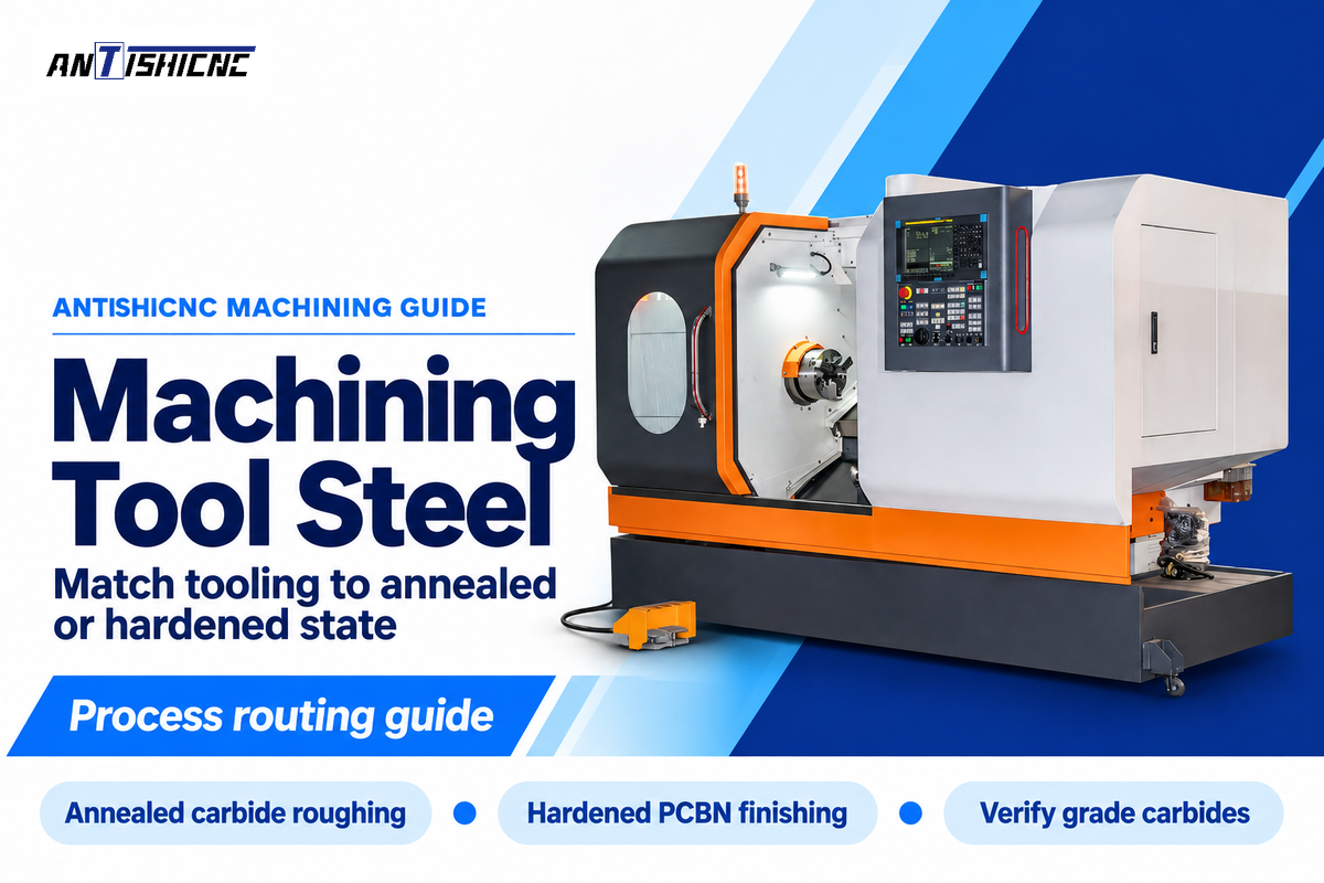
In industrial die, mold, and shaft production, machining tool steel is executed across two distinct metallurgical states: roughing spheroidize-annealed stock (18 to 24 HRC / 190 to 255 HBW) at 75 to 150 m/min (245 to 490 SFM) using CVD or PVD coated carbide cutting tools, or finish-cutting quenched-and-tempered stock (55 to 62 HRC) at 90 to 180 m/min (295 to 590 SFM) using polycrystalline cubic boron nitride (PCBN), mixed ceramic, or nano-coated solid carbide tooling per ASTM A681 そして ISO 3685. Selecting between annealed roughing and hardened finishing depends on primary carbide volume across O1, A2, D2, S7, H13, and M2/M42 grades, heat-treatment distortion allowances, thermal-shock cooling rules, and CNC machine rigidity. Engineers selecting tool steel materials for stamping dies require exceptionally high contact fatigue resistance across the finished punch edge. Shops using cnc machining services and special tool steel machining services therefore employ soft roughing and hard finishing as a unified machining service.
Direct Engineering Answer: Rough spheroidize-annealed stock (18–24 HRC) with P25, P35 coated inserts at ap ≥ 1.5–2.0 mm and 8–10% flood emulsion, leaving 0.25–0.50 mm (A2/D2/H13) or 0.50–1.00 mm (O1) of semi-finish allowance per side before quenching. Finish continuous cuts on 55–62 HRC workpieces with 45–55% low-CBN tips, interrupted cuts with 80–90% high-content PCBN, and hard-milled features with TiSiN end mills, all under dry air blast.
Key Takeaways for Tool Steel CNC Turning and Milling
- Bulk Brinell or Rockwell hardness doesn’t tell the whole story: annealed D2 at 215 HBW wears carbide tools 2.5 times faster than 4140 at 215 HBW because D2 contains 1,500 to 1,800 HV chromium carbides (M 7 C 3 ) and 2,400 to 2,800 HV vanadium carbides (MC).
- Relative machinability ratings compared with AISI B1112 (100%) step down from O1 (80–85%) and S7 (75%) to A2 (60–65%), H13 (55–60%), M2 (40–45%), D2 (30–40%), and M42 (25–30%).
- Hard turning at 58-62 HRC with low-content PCBN inserts (45-55% CBN) outperform high-content PCBN (80-90% CBN) inserts. This is due to chemical cratering diffusion and retention of heat in the shear zone.
- Negative-rake hard turning generates passive radial thrust forces (Fp) 1.5 to 2.5 times greater than the cutting force (Fc). Negative-rake hard turning generates passive radial thrust forces (F p ) 1.5 to 2.5 times higher than tangential cutting forces (F c ), so it calls for a rigid machine such as a heavy slant-bed CNC lathe or one with induction-hardened box ways; for hard milling, Modern Machine Shop recommends shrink-fit or hydraulic holders with TIR ≤ 0.003 mm.
Tool Steel Machinability and Metallurgy: Why Carbide Volume and Hardness Govern Cutting
Tool steel is harder to cut than standard carbon and alloy steels of identical bulk hardness, because tool steel metallurgy relies on dense dispersions of hard chromium, vanadium, tungsten, and molybdenum carbides embedded in the iron matrix. Even when a cold-work tool blank is spheroidize-annealed to 18 to 24 HRC (190 to 255 HBW) per ASTM A681, those wear-resistant microscopic carbide particles remain at 1,500 to 2,800 HV and act like abrasive grit against the cutting edge. Carbide volume governs flank wear. Matrix hardness governs cutting force.
“Under ASTM A681 and ISO 3685 single-point turning benchmarks, abrasive flank wear in high-carbon high-chromium tool steels is controlled by primary M7C3 and MC carbide volume fraction rather than annealed ferrite matrix hardness alone, requiring sub-micron carbide or PCBN substrates before flank wear land VB exceeds 0.20 mm.”, ASTM A681 / ISO 3685 Metallurgical & Tool-Life Testing Reference Synthesis
In plain low-alloy grades like AISI 1045 or 4140, the hard phase is iron cementite (Fe 3 C), which measures roughly 800 to 1,000 HV, well below the 1,500 to 1,800 HV hardness of a tungsten carbide tool substrate. As documented in tool steel metallurgical classifications, alloying with 5 to 12 wt% chromium forms M7C3 carbides at 1,500 to 1,800 HV, while tungsten and molybdenum form M6C carbides at 1,500 to 1,650 HV, and vanadium forms MC carbides at 2,400 to 2,800 HV. Because vanadium carbides are harder than uncoated cemented carbide inserts, high-vanadium grades abrade tool flanks rapidly during tool steel machining.
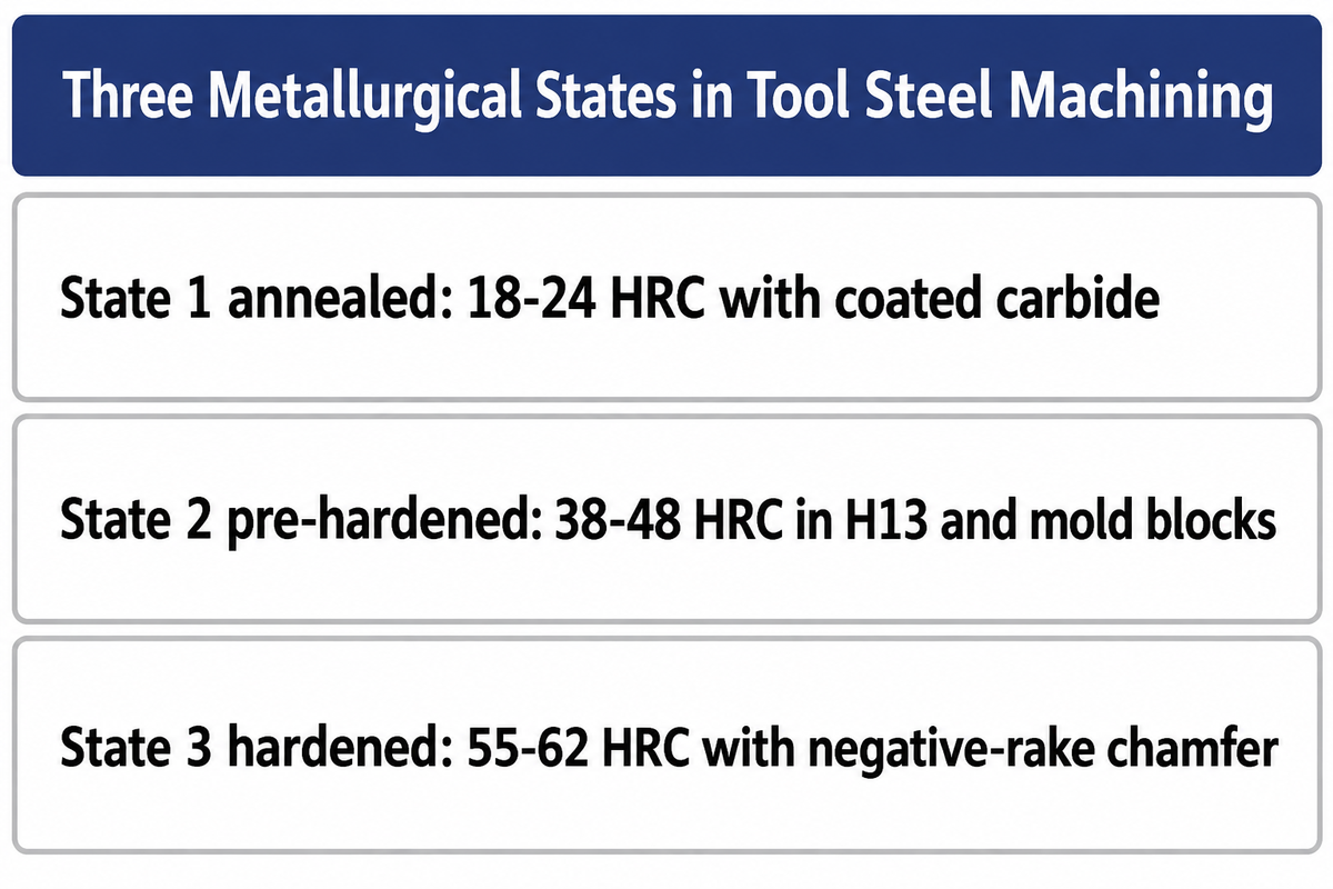
To evaluate mechanical properties, process engineers consider three different delivery states and three heat-treat states. In State 1 (spheroidize-annealed, 18–24 HRC), carbides sit as rounded globules inside soft ferrite; specific cutting force k c1.1 is moderate (1,900 to 2,400 N/mm²), but gummy ferrite can weld onto the tool nose at low speeds. In State 2 (pre-hardened or quenched and tempered to 38-48 HRC, which is common in H13 hot-work dies and in plastic mold blocks), tempered martensite increases kc1.1 to 2,600-3,200 N/mm². In State 3 (fully hardened at 55-62 HRC), martensite is softened by thermal energy that’s concentrated in the shear zone. A negative-rake chamfer is used to promote the shearing of the martensite.
3-State Carbide & Hardness Machinability Matrix
| Material & Metallurgical State | Bulk Hardness (HBW / HRC) | Primary Carbide Phase & Micro-Hardness | Specific Cutting Force kc1.1 (N/mm²) | Dominant Tool Wear Mechanism | Primary Tooling Substrate |
|---|---|---|---|---|---|
| Baseline: Low-Alloy Steel (AISI 4140 Annealed) | 197–220 HBW | Fe3C Cementite (800–1,000 HV) | 1,700–1,950 N/mm² | Normal flank & crater wear | ISO P15–P25 CVD Coated Carbide |
| State 1a: Low-Alloy Cold-Work (O1 / W1 Annealed) | 185–212 HBW (14–18 HRC) | Spheroidized (Fe,Cr)3C (900–1,100 HV, ~3–5 vol%) | 1,900–2,100 N/mm² | Built-up edge (BUE) & chip welding | ISO P20–P30 CVD/PVD Coated Carbide |
| State 1b: Medium-Alloy Air/Hot-Work (A2 / S7 / H13 Annealed) | 195–235 HBW (16–22 HRC) | Cr M7C3 (1,500–1,800 HV) + V MC (~5–8 vol%) | 2,100–2,350 N/mm² | Abrasive flank wear + notch wear at scale | ISO P25–P35 TiCN/Al2O3 or TiAlN Carbide |
| State 1c: High-Cr / HSS (D2 / M2 / M42 Annealed) | 215–255 HBW (19–25 HRC) | M7C3 + W/Mo M6C + V MC (2,400–2,800 HV, 12–20 vol%) | 2,350–2,700 N/mm² | Severe two-body carbide abrasion & edge micro-chipping | Sub-Micron PVD AlTiN / TiSiN Tough Carbide |
| State 2: Pre-Hardened Die & Mold Steel (H13 / P20 / S7) | 370–450 HBW (40–48 HRC) | Tempered Martensite + Secondary Cr/Mo/V Carbides | 2,650–3,200 N/mm² | Plastic deformation + thermal comb cracking | ISO H15–H25 PVD AlTiN Carbide or Mixed Ceramic |
| State 3a: Hardened Cold/Hot-Work (O1 / A2 / S7 / H13 Q&T) | 550–690 HV (52–59 HRC) | High-Hardness Tempered Martensite + Alloy Carbides | 3,300–4,100 N/mm² | Shear-zone crater diffusion & high passive radial force Fp | Low-Content PCBN (50% CBN) or Nano-TiSiN Carbide |
| State 3b: Hardened High-Cr & HSS (D2 / M2 / M42 Q&T) | 690–880 HV (60–66 HRC) | Martensite + Coarse M7C3 / M6C / MC Carbide Network | 4,000–4,800 N/mm² | Catastrophic edge fracture on carbide stringers + white layer | Honed T-Land PCBN (ISO H05–H15) or CBN Grinding |
| State 3c: Interrupted Hardened Cuts (Keyways / Die Cavities) | 600–760 HV (55–62 HRC) | Tempered Martensite Subjected to Cyclic Impact Load | 3,600–4,400 N/mm² (cyclic) | Mechanical impact spalling & thermal shock fracture | High-Content PCBN (80–90% CBN) or Dynamic 5-Axis TiSiN |
| State 3d: Powder Metallurgy (PM) Tool Steel (CPM 10V / M4) | 700–840 HV (60–64 HRC) | Fine Uniform 2–4 μm Vanadium MC Carbides (2,800 HV) | 4,100–4,600 N/mm² | Uniform micro-abrasion without coarse stringer chipping | Fine-Grain Low-CBN or Diamond/CBN Creep-Feed Grinding |
Is Tool Steel Hard to Machine Compared With Standard Carbon and Alloy Steels?
Yes, most annealed tool steels are significantly harder to machine than plain carbon steel (such as 1018) or low-alloy steel (such as 4140); well-spheroidized O1 is the exception and machines on par with 1018. While 1018 steel has a machinability rating around 78% relative to AISI B1112, annealed tool steels range from 80% for oil-hardening O1 down to 30% for high-chromium D2 and 25% for M42 high-speed steel due to abrasive alloy carbides and rapid work hardening. Rapid work hardening is the primary cause for the low machinability.
Tool Steel Grade Comparison: Machining O1, A2, and D2 Cold-Work vs H13 Hot-Work, S7, and M2/M42 HSS
Selecting the right cutting speed and insert geometry requires comparing the exact chemical composition and carbide morphology of each grade. In the spheroidize-annealed delivery condition defined by ASTM A681 そして ASTM A600, relative machinability ratings (where free-machining AISI B1112 equals 100%) span nearly a 3.5-to-1 ratio: O1 machines at 80–85%, S7 at 75%, A2 at 60–65%, H13 at 55–60%, M2 at 40–45%, D2 at 30–40%, and M42 at 25–30% in published tool steel machinability benchmarks. Grade chemistry sets the speed limit. Carbide size sets edge life.
Within the cold work tool steel group, oil-hardening O1 (0.90% C, 1.20% Mn, 0.50% Cr, 0.50% W) is easy to machine when properly spheroidized, producing clean shear chips during turning and milling. Air-hardening A2 (1.0% C, 5.0% Cr, 1.0% Mo) offers a balanced middle ground with deep hardenability, and it provides good toughness and excellent dimensional stability during heat treatment. The parameter table recommends higher annealed cutting speeds for A2 than for D2, but not nearly twice the speed. High-carbon, high-chromium D2 tool steel (1.55% C, 11.5–12.0% Cr, 0.80% Mo, 0.90% V) delivers high wear resistance and mild corrosion resistance for long-run stamping dies, while related air-hardening grades like tool steel A3 (1.25% C, 5.0% Cr, 1.0% V) add vanadium for extra abrasion resistance. However, conventional ingot-cast tool steel D2 contains coarse, segregated M7C3 carbide stringers up to 30 to 50 μm long that hammer the cutting edge and cause micro-chipping.
Beyond cold-work grades, shock-resisting S7 (0.50% C, 3.25% Cr, 1.40% Mo) provides high toughness for chisels, punches, and shear blades. Chromium hot-work H13 (0.40% C, 5.0% Cr, 1.35% Mo, 1.0% V) is the global standard for aluminum die-casting dies, extrusion tooling, and high-temperature plastic mold inserts because it resists thermal fatigue checking while maintaining toughness and excellent dimensional stability. High-speed steels M2 (6% W, 5% Mo, 4% Cr, 2% V) and cobalt-alloyed M42 (8% Co, 9.5% Mo, 1.5% W) are engineered for rotary cutters and punches that need the ability to hold a cutting edge at elevated temperatures; their dense M6C and MC carbide networks demand reduced surface speeds and rigid setups when combining CNC turning and milling operations on complex workpieces.
| AISI / ASTM Grade | Tool Steel Class | Nominal Alloy Chemistry (wt%) | Annealed HBW (Working HRC) | Relative Machinability vs W1 Carbon Tool Steel (%) | Carbide Morphology & Shop-Floor Cutting Behavior |
|---|---|---|---|---|---|
| O1 (ASTM A681) | Oil-Hardening Cold-Work | 0.90 C, 1.2 Mn, 0.5 Cr, 0.5 W | 185–212 HBW (58–62 HRC) | 80–85% | Fine spheroidized carbides; easiest alloy tool steel to turn, mill, and thread |
| S7 (ASTM A681) | Shock-Resisting | 0.50 C, 3.25 Cr, 1.40 Mo, 0.25 V | 187–223 HBW (54–58 HRC) | 75% | Lower carbon yields gummy, stringy chips in annealed turning; use positive chipbreakers |
| A2 (ASTM A681) | Air-Hardening Cold-Work | 1.00 C, 5.0 Cr, 1.0 Mo, 0.25 V | 201–235 HBW (57–62 HRC) | 60–65% | Moderate M7C3 carbides; predictable flank wear and low quench distortion |
| H13 (ASTM A681) | Chromium Hot-Work | 0.40 C, 5.0 Cr, 1.35 Mo, 1.0 V, 1.0 Si | 192–229 HBW (45–54 HRC) | 55–60% | Tough matrix + 1% V carbides; frequently hard-milled at 46–52 HRC with AlTiN carbide |
| P20 / Mold Steel | Plastic Mold Steel | 0.35 C, 1.7 Cr, 0.40 Mo | 280–320 HBW (30–34 HRC pre-hard) | 65–70% | Supplied pre-hardened; machines cleanly without post-machining heat treatment |
| M2 (ASTM A600) | W-Mo High-Speed Steel | 0.85 C, 6.0 W, 5.0 Mo, 4.0 Cr, 2.0 V | 212–248 HBW (60–65 HRC) | 40–45% | High volume of M6C and MC carbides; calls for slow speeds when annealed, with flood coolant typical for turning and drilling and dry air blast an option for carbide milling |
| D2 (ASTM A681) | High-C High-Cr Cold-Work | 1.55 C, 12.0 Cr, 0.80 Mo, 0.90 V | 217–255 HBW (58–62 HRC) | 30–40% | ~15–18 vol% coarse M7C3 carbide bands; highly abrasive in both soft and hard states |
| M42 (ASTM A600) | Cobalt High-Speed Steel | 1.10 C, 8.0 Co, 9.5 Mo, 1.5 W, 1.15 V | 235–269 HBW (65–69 HRC) | 25–30% | Cobalt solid-solution strengthening raises shear stress and cutting temperature |
| PM Tool Steels (CPM 3V / M4) | Powder Metallurgy Cold-Work | 0.8–1.4 C, 4–5 Cr, 2.75–4.0 V, W/Mo | 220–255 HBW (58–64 HRC) | 45–55% | Gas-atomized 2–4 μm carbides eliminate stringer chipping and out-machine cast D2 |
What Is the Easiest Tool Steel to Machine in the Annealed Condition?
Water-hardening W1 and oil-hardening O1 tool steels are the easiest tool steels to machine in the spheroidize-annealed condition and achieve about 80% to 90% machinability relative to AISI B1112. As tool steel O1 has minimal chromium (0.5%) and vanadium as compared to tool steel A2 or D2, it has relatively fine primary carbides and cuts with standard coated carbide inserts. Among air-hardening grades, tool steel A2 (60-65%) and shock-resisting S7 (75%) are the easier options before abrasive D2.
Machining Annealed Tool Steel (18–24 HRC): Coated Carbide Roughing, Milling, and Drilling
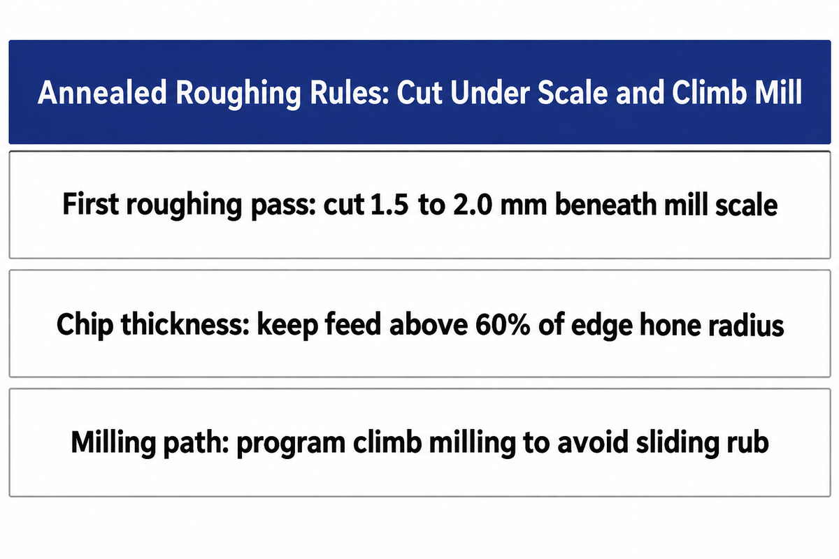
Roughing spheroidize-annealed tool steel (185 to 255 HBW, up to about 24 HRC) accounts for 85% to 95% of total chip removal before the workpiece enters the heat-treat furnace. Success in annealed roughing depends on two mechanical rules documented in Practical Machinist tool steel milling benchmarks そして machinability mechanics: penetrating at least 1.5 to 2.0 mm (0.060 to 0.080 in.) beneath the hot-rolled mill scale on the first pass, and keeping uncut chip thickness above 60% of the cutting edge hone radius (fz ≥ 0.08 to 0.15 mm/tooth) to prevent rubbing without cutting. Deep cuts get under the scale. Positive feeds stop work hardening.
Hot-rolled tool steel bar and plate arrive from the mill with an oxidized scale and a decarburized surface layer (bark) mixed with silica and iron oxides. Skimming that skin with a shallow 0.4 mm pass forces the sensitive nose radius to ride directly inside the abrasive scale line, creating a deep depth-of-cut notch within minutes. Operators applying CNC turning operations and lathe setup fundamentals should program a first roughing depth of cut of 2.0 to 4.5 mm using a tough ISO P25, P35 CVD TiCN/Al2O3 coated carbide insert in a holder that sets the entering angle (for example, SNMG at 45° or 75°, or CNMG at 75°) so the main cutting edge shears clean base metal beneath the bark.
When milling tool steel in the annealed state on a rigid, backlash-free CNC machine, program climb milling (down-milling) rather than conventional up-milling. In conventional milling, the flute enters the cut at zero chip thickness and slides across the alloy surface until radial pressure builds enough to bite; that sliding zone causes severe rubbing without cutting, work-hardening the surface skin and spiking tool temperature. Climb milling starts each tooth at maximum chip thickness and exits thin, thus directing heat into the chip and protecting surface finish and extending tool life on every milling tool and solid carbide end mill.
| Annealed Operation (18–24 HRC) | Recommended Cutter & Coating | Lead Angle & Rake Geometry | Depth of Cut (ap) & Stepover (ae) | Anti-Work-Hardening Shop Rule |
|---|---|---|---|---|
| 1. Scale-Breaking Rough Turning | ISO P30 CVD TiCN + α-Al2O3 炭化物 | 45°–75° lead; medium-positive chipbreaker | ap = 2.0–5.0 mm (under mill bark) | Never dwell on shoulders; keep fn ≥ 0.20 mm/rev to break stringy O1/S7 chips |
| 2. Semi-Finish Contour Turning | ISO P20 CVD/PVD TiAlN Coated Carbide | 93°–95° (DNMG / VNMG); rε = 0.8 mm | ap = 0.5–1.5 mm | Maintain Vc ≥ 90 m/min to prevent built-up edge (BUE) tearing on soft ferrite |
| 3. Face Milling & Squaring Blocks | Indexable 45° Face Mill or Round Button Cutter | 45° lead angle or RPKX round insert | ap = 1.5–3.5 mm; ae = 65–75% D | Position cutter off-center for 70/30 climb milling; roll into entry cut rather than plunging |
| 4. High-Feed Cavity Roughing | PVD AlTiN High-Feed Mill (HFM) | 10°–15° low lead angle (axial force vector) | ap = 0.6–1.2 mm; ae = 55–65% D | Apply fz = 0.5–1.2 mm/tooth to compensate for low lead angle chip thinning |
| 5. Dynamic / Trochoidal Slotting | 5- or 6-Flute Variable-Helix Solid Carbide End Mill | 38°–42° unequal helix; core-reinforced | ap = 1.5–2.0×D; ae = 8–15% D | Helical ramp into pockets at 2°–3°; never full-width slot D2 or M2 with carbide |
| 6. Through-Coolant Drilling | Internal-Coolant TiAlN Solid Carbide Drill | 140° self-centering point; honed margin | Continuous up to 5×D (40–70 bar coolant) | Avoid short peck cycles with carbide drills; retracting traps chips that shatter the point |
| 7. Internal Threading (Before Heat Treat) | TiCN Spiral-Flute PM-HSS Tap or Carbide Thread Mill | 45° spiral flute (blind) or multi-tooth thread mill | Tap drill at 70–75% thread height (not 85%) | Thread milling sharply reduces broken-tap scrap in expensive D2/H13 blocks |
| 8. Deep Cavity Hogging (>30% Stock Removal) | Indexable Porcupine / Helical Mill + Roughing Pass | Positive-rake tangential or square inserts | Leave 1.5–2.0 mm stock before stress relief | Schedule 600–650 °C sub-critical stress relief before semi-finishing to 0.3–0.5 mm stock |
Will Carbide Cut Tool Steel Without Premature Edge Chipping or Rubbing?
Yes, coated cemented carbide is the primary tooling material for cutting annealed and pre-hardened tool steel (18 to 48 HRC) and for high-speed hard milling up to 60–62 HRC. To prevent edge chipping in abrasive grades like D2 or M2, machinists choose sub-micron grain carbide substrates (6 to 10 wt% cobalt binder) coated with PVD TiAlN, AlTiN or nano-composite TiSiN, use a 0.02 to 0.05 mm honed edge preparation and maintain climb milling chip loads above 0.06 to 0.12 mm/tooth.
Machining Hardened Tool Steel (55–62 HRC): PCBN Hard Turning, Ceramic Inserts, and 5-Axis Hard Milling
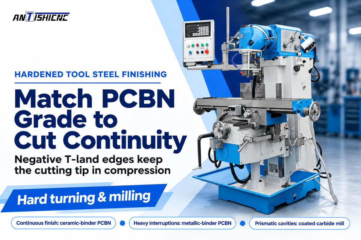
Turning inserts made from positive-rake carbide fail rapidly due to plastic deformation when workpieces reach 55 to 62 Rockwell C (HRC). In PCBN Hard Turning of hardened tool steel, negative-rake edges with a 15° to 25° T-land chamfer as described in US Patent US6544649B1 そして Sandvik Coromant hard-part turning guidelines, help to manage the high cutting load and focus heat in the shear zone, thus softening the hardened steel to form a chip. Negative T-land edges maintain the PCBN tip in compression. Shear in the cutting zone softens the steel.
A common error with hard turning hardened steel is assuming that a higher cubic boron nitride (CBN) content results in longer tool life. This is discussed in detail in Tungaloy’s PCBN hard turning reference and in 切削工具エンジニアリング. PCBN inserts are of two types of metallurgical classes and are therefore classified as:
- In continuous cuts, low-content PCBN (45% to 55% CBN with a TiCN / TiN ceramic binder) performs best: the ceramic binder lowers thermal conductivity, concentrating heat in the shear zone to plasticize 60 HRC steel, and provides superior chemical stability against iron diffusion, outlasting high-CBN grades by 2x in continuous finish hard turning per Tungaloy and Cutting Tool Engineering benchmarks.
- In heavy interruptions, High-Content PCBN (80% to 90% CBN with Co / Ni / Al Metallic or Cermet Binder): Dense grain-to-grain CBN bonding raises fracture toughness to survive heavy interrupted cuts (such as cross-holes, splines, or keyways on a slant-bed CNC turning and milling center configuration), but wears faster by chemical cratering in long continuous passes.
For prismatic cavities and forging dies, 5-axis CNC hard milling using ultrafine solid carbide end mills coated with AlTiN or nano-crystalline TiSiN (oxidation resistance up to 1,100 °C and surface hardness ~3,500 HV) enables direct finishing of 52 to 62 HRC tool steel. Short, stub-length, ball-nose or bull- nose, cutters tilted at 10° to 15° lead angle on a 5- axis CNC machining center avoid zero surface speed rubbing at the ball center and help eliminate manual bench polishing of hardened die surfaces.
| Hard-Machining Tool Substrate | Binder / Coating Composition | Vickers Hardness & Hot Limit | Optimal Workpiece Hardness & Cut Type | Edge Preparation (T-Land / Hone) | Achievable Tolerance & Finish (Ra) |
|---|---|---|---|---|---|
| 1. Low-Content PCBN (ISO H05–H15) | 45–55 vol% CBN + TiCN/TiN ceramic binder (+ TiAlN PVD coat) | 2,800–3,200 HV; 1,200 °C | 55–64 HRC continuous & light-interrupted finish turning | 15°–20° × 0.10–0.15 mm negative T-land + 0.02 mm hone (S-land) | IT5–IT6 (±0.005 mm); Ra 0.2–0.4 μm (wiper) |
| 2. High-Content PCBN (ISO H20–H30) | 80–90 vol% CBN + Co/Ni/AlN binder | 3,500–4,200 HV; 1,150 °C | 55–62 HRC heavy interrupted turning & face milling | 25°–30° × 0.15–0.25 mm heavy T-land + 0.03–0.05 mm hone | IT6–IT7; Ra 0.4–0.8 μm |
| 3. Mixed Ceramic (Al2O3 + TiCN) | 70% Al2O3 + 30% TiCN black ceramic | 2,000–2,300 HV; 1,400 °C | 48–58 HRC continuous rough & semi-finish turning only | 20° × 0.15–0.20 mm T-land (brittle in interruptions) | IT6–IT7; Ra 0.4–1.2 μm |
| 4. Whisker Ceramic (Al2O3 + SiCw) | Al2O3 reinforced with 20–30% SiC whiskers | 2,100–2,400 HV; 1,350 °C | 50–60 HRC high-Cr D2 roughing & hard groove turning | 20° × 0.20 mm T-land or round RNGN insert | IT7; Ra 0.8–1.6 μm |
| 5. Nano-Coated Solid Carbide End Mill | 0.2–0.5 μm WC-Co (6–8% Co) + PVD AlTiN / TiSiN | 3,300–3,800 HV (coat); 1,100 °C | 48–62 HRC 3-axis & 5-axis high-speed hard milling | -5° to -12° negative radial rake + K-land micro-hone | ±0.005–0.010 mm; Ra 0.2–0.6 μm |
| 6. Brazed/Solid PCBN Ball-Nose End Mill | Fine-grain binderless or low-binder PCBN tip | 3,200–4,000 HV; 1,200 °C | 60–66 HRC optical-finish die & punch contour milling | Negative radial rake; ap ≤ 0.05 mm; ae ≤ 0.10 mm | ±0.003 mm; Ra 0.05–0.15 μm |
Can You Machine Hardened D2 Tool Steel Above 58 HRC Without Grinding?
Yes, hardened D2 tool steel at 58 to 62 HRC can be finish-turned and hard-milled without cylindrical or surface grinding when the drawing calls for IT5, IT6 tolerances and Ra 0.2 to 0.4 μm surface finishes; tighter drawing requirements still call for grinding. For rotational D2 punches, rolls, and slitter knives, low-content PCBN inserts (50% CBN with a 20° by 0.12 mm negative T-land and wiper geometry) turn 60 HRC D2 at 90 to 130 m/min (295 to 425 SFM), holding ±0.005 mm tolerances and Ra 0.25 μm finish. For prismatic D2 stamping dies, 6-flute TiSiN-coated solid carbide end mills hard-mill 60 HRC surfaces at 60 to 100 m/min using 5% to 8% radial stepovers and dry air blast.
Cutting Speeds, Feeds, and Depth of Cut Parameters: Annealed Carbide vs Hardened CBN and Ceramic
Programming CNC machining of tool steel involves matching surface speed (Vc), feed per revolution (fn) or feed per tooth (fz), and depth of cut (ap) to both the alloy’s carbide volume and its heat-treatment state. Based on Sandvik Coromant そして Seco Tools hard milling tables, annealed roughing with coated carbide runs at 45 to 160 m/min with axial cuts of 1.0 to 4.5 mm, whereas hardened PCBN turning runs at 70 to 180 m/min and TiSiN hard milling at 40 to 145 m/min, both with shallow depths of cut (0.04 to 0.60 mm) so shear-zone heat softens the chip without overloading the cutting edge.
When calculating surface feet per minute (SFM) and spindle RPM for high-speed hard milling, programmers must account for radial chip thinning. Whenever radial stepover (ae) drops below 50% of cutter diameter (D), the maximum uncut chip thickness (hex) becomes thinner than the programmed feed per tooth (fz); the gap is small near 50% but widens sharply at the 5% to 10% stepovers used in hard milling. Running an uncompensated fz at ae = 5% to 8% D starves the cutting edge and causes abrasive rubbing; multiplying the target chip thickness by the Radial Chip-Thinning Factor (RCTF) restores proper shear bite and high-performance metal removal.
| Tool Steel Grade & Condition | Hardness State | Turning Vc: m/min (SFM) | Turning fn (mm/rev) & ap (mm) | Milling Vc: m/min (SFM) | Milling fz (mm/t) & ap / ae |
|---|---|---|---|---|---|
| O1 — Annealed (Coated Carbide) | 185–212 HBW (~16 HRC) | 120–160 (395–525 SFM) | fn 0.20–0.45; ap 1.5–4.5 | 110–150 (360–490 SFM) | fz 0.10–0.20; ap 2–4 mm, ae 50% D |
| O1 — Hardened (PCBN / TiSiN Mill) | 58–62 HRC | 130–180 (425–590 SFM) | fn 0.06–0.16; ap 0.05–0.25 | 90–140 (295–460 SFM) | hex 0.03–0.06; ap 0.2–0.5, ae 5–10% D |
| A2 — Annealed (Coated Carbide) | 201–235 HBW (~20 HRC) | 100–135 (330–440 SFM) | fn 0.18–0.40; ap 1.5–4.0 | 90–125 (295–410 SFM) | fz 0.08–0.18; ap 1.5–3.5 mm, ae 40% D |
| A2 — Hardened (PCBN / TiSiN Mill) | 58–62 HRC | 110–160 (360–525 SFM) | fn 0.05–0.15; ap 0.05–0.25 | 80–120 (260–395 SFM) | hex 0.03–0.05; ap 0.15–0.4, ae 5–8% D |
| D2 — Annealed (Coated Carbide) | 217–255 HBW (~22 HRC) | 75–110 (245–360 SFM) | fn 0.15–0.35; ap 1.5–3.5 | 65–95 (215–310 SFM) | fz 0.07–0.14; ap 1.5–3.0 mm, ae 30% D |
| D2 — Hardened (PCBN / TiSiN Mill) | 58–62 HRC | 90–140 (295–460 SFM) | fn 0.05–0.12; ap 0.05–0.20 | 60–100 (195–330 SFM) | hex 0.025–0.045; ap 0.1–0.3, ae 5–8% D |
| S7 — Annealed (Coated Carbide) | 187–223 HBW (~18 HRC) | 110–145 (360–475 SFM) | fn 0.20–0.40; ap 1.5–4.0 | 100–135 (330–440 SFM) | fz 0.09–0.18; ap 1.5–3.5 mm, ae 45% D |
| S7 — Hardened (PCBN / TiSiN Mill) | 54–58 HRC | 120–165 (395–540 SFM) | fn 0.06–0.15; ap 0.05–0.25 | 85–130 (280–425 SFM) | hex 0.03–0.06; ap 0.2–0.5, ae 6–10% D |
| H13 — Annealed (Coated Carbide) | 192–229 HBW (~19 HRC) | 95–130 (310–425 SFM) | fn 0.18–0.38; ap 1.5–4.0 | 85–120 (280–395 SFM) | fz 0.08–0.16; ap 1.5–3.5 mm, ae 40% D |
| H13 — Hardened (PCBN / TiSiN Mill) | 48–54 HRC | 120–170 (395–560 SFM) | fn 0.06–0.16; ap 0.08–0.30 | 90–145 (295–475 SFM) | hex 0.035–0.065; ap 0.2–0.6, ae 6–12% D |
| M2 / M42 — Annealed (PVD Carbide) | 212–269 HBW (20–27 HRC) | 50–80 (165–260 SFM) | fn 0.12–0.28; ap 1.0–3.0 | 45–75 (150–245 SFM) | fz 0.06–0.12; ap 1.0–2.5 mm, ae 25% D |
| M2 / M42 — Hardened (PCBN Turning) | 62–67 HRC | 70–110 (230–360 SFM) | fn 0.04–0.10; ap 0.04–0.15 | 40–65 (130–215 SFM) | hex 0.02–0.035; ap 0.08–0.2, ae 4–6% D |
n (RPM) = 1000 · Vc / (3.14 · D) | RCTF = 1 / [1 – (1 – 2 · ae/D)2] 0.5 | fz,prog = hex · RCTF | vf = n · z · fz,prog
Worked Radial Chip-Thinning Example (Assumed Shop-Floor Setup on D2 Tool Steel): Compare side-milling an assumed AISI D2 stamping die block using a ∅12.0 mm (D = 12 mm), 6-flute (z = 6) TiSiN-coated solid carbide end mill in the annealed state vs the hardened 58 HRC state:
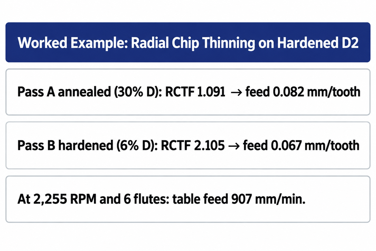
- Specifically, Pass A, Annealed D2 Roughing (220 HBW, Assumed Vc = 80 m/min, ae = 3.6 mm [30% D], ap = 12.0 mm, target hex = 0.075 mm): Spindle speed n = (1,000 × 80) / (3.1416 × 12) = 2,122 RPM. At ae/D = 0.30, RCTF = 1 / √[1 – (1 – 0.60)²] = 1 / √0.84 = 1.091. Programmed feed per tooth fz,prog = 0.075 × 1.091 = 0.082 mm/tooth, giving table feed vf = 2,122 × 6 × 0.082 = 1,044 mm/min (MRR Q = 45.1 cm³/min).
- Specifically, Pass B, Hardened 58 HRC D2 Finishing (Assumed Vc = 85 m/min, ae = 0.72 mm [6% D], ap = 6.0 mm, target hex = 0.032 mm): Spindle speed n = (1,000 × 85) / (3.1416 × 12) = 2,255 RPM. Because radial engagement is only 6% of diameter (ae/D = 0.06), RCTF = 1 / √[1 – (1 – 0.12)²] = 1 / √(1 – 0.7744) = 1 / 0.475 = 2.105. To achieve a true 0.032 mm chip thickness without rubbing, programmed feed per tooth must double to fz,prog = 0.032 × 2.105 = 0.067 mm/tooth, yielding a fast table feed of vf = 2,255 × 6 × 0.067 = 907 mm/min under dry air blast.
Heat Treatment Distortion, Stress-Relief Stock Allowance, and Hard Turning vs Grinding Economics
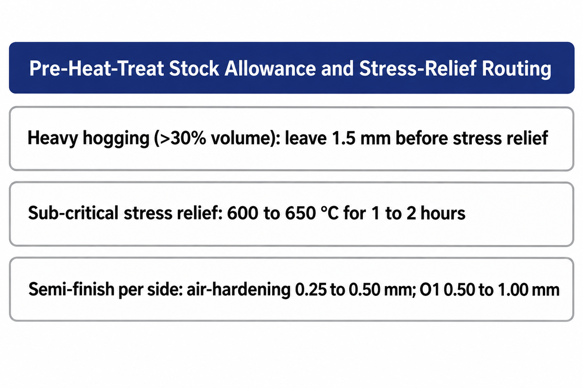
Routing precision tool steel parts from raw bar to finished tolerance requires leaving semi-finish stock before heat treatment to absorb quench warpage, martensitic volume expansion, and surface decarburization. As documented in heat-treating distortion benchmarks, air-hardening grades (A2, D2, H13) require 0.25 to 0.50 mm (0.010 to 0.020 in.) of stock per side on medium cross-sections, whereas oil-quenched O1 requires 0.50 to 1.00 mm (0.020 to 0.040 in.) per side because steeper thermal quench gradients induce greater bending and ovality. Too little stock leaves dark scale. Too much stock burns up CBN inserts.
There are two metallurgical rules which govern dimensional stability in complex tools and dies. More than 30% of a block’s volume before machining to semi-finish pre-quench dimensions, the roughed block, left with about 1.5 mm of stock, receives a sub-critical stress-relief anneal at 600 to 650 °C (1,110 to 1,200 °F) for 1 to 2 hours followed by slow furnace cooling, and is then semi-finished to the grade’s pre-heat-treat allowance shown in the table below prior to austenitizing. Second, in ingot-cast D2, refinement of carbide (carbide) during hardening is directional due to the nature of the rolling process. Second, ingot-cast D2 exhibits pronounced anisotropic growth during hardening: because elongated M 7 C 3 carbide stringers align with the rolling direction, longitudinal expansion along the bar axis can reach roughly twice the transverse expansion across the bar width, and tempering doesn’t remove this directionality; powder-metallurgy tool steels, which disperse 2–4 μm carbides uniformly, reduce it. Tightly dispersed 2 to 4 μm carbides in a powder-metallurgy tool steels (refractory metal) reduce this directional expansion.
After quenching and double or triple tempering to working hardness (58–62 HRC for cold-work grades, 48–52 HRC for H13), shops choose between cylindrical/surface grinding and single-setup PCBN hard turning or 5-axis hard milling. As confirmed in hard-turning surface integrity studies, PCBN hard turning on a rigid lathe achieves IT5, IT6 dimensional accuracy (±0.004 to ±0.008 mm) and Ra 0.2 to 0.4 μm roughness while cutting cycle times by 40% to 65%, machining ODs, IDs, tapers, and faces in a single chucking with beneficial compressive residual stress instead of tensile grinding burn. Applying CNC hard turning to heat-treated parts eliminates secondary fixture transfers between lathes and grinders. That single-setup workflow preserves steel precision and concentricity across multi-stepped precision parts.
| Tool Steel Grade | Quench Medium & Austenitizing Temp | Typical Dimensional Change (%) | Pre-Heat-Treat Stock per Side (L/D ≤ 3) | Slender Shafts / Plates (L/D > 5) | Post-Quench Finishing Method |
|---|---|---|---|---|---|
| A2 (Air-Hardening) | Air / Gas Quench; 925–970 °C | +0.04% to +0.10% (isotropic) | 0.20–0.35 mm (0.008–0.014 in.) | 0.40–0.65 mm (0.016–0.025 in.) | 1–2 pass Low-CBN hard turning or TiSiN hard milling |
| D2 (High-Cr Air-Hardening) | Vacuum / Air Quench; 980–1,025 °C | +0.08–0.14% (long.) / +0.04% (trans.) | 0.25–0.45 mm (0.010–0.018 in.) | 0.50–0.80 mm (anisotropic bow) | PCBN hard turning (ap ≤ 0.20 mm/pass) or CBN grinding |
| H13 (Hot-Work Die Steel) | High-Pressure Gas / Air; 1,010–1,050 °C | +0.05% to +0.12% | 0.25–0.50 mm (0.010–0.020 in.) | 0.50–0.75 mm (cavity warpage) | 5-axis CNC hard milling at 48–52 HRC or PCBN turning |
| S7 (Shock-Resisting) | Air (≤60 mm) or Oil; 925–955 °C | +0.08% to +0.15% | 0.30–0.50 mm (0.012–0.020 in.) | 0.60–0.90 mm (0.024–0.035 in.) | PCBN turning or AlTiN carbide milling at 54–58 HRC |
| O1 (Oil-Hardening) | Warm Oil Quench; 790–815 °C | +0.15% to +0.25% | 0.50–0.80 mm (0.020–0.032 in.) | 0.80–1.25 mm (0.032–0.050 in.) | Multi-pass PCBN semi-finish + finish or cylindrical grind |
| M2 / M42 (High-Speed Steel) | Vacuum / Salt Quench; 1,190–1,230 °C | +0.12% to +0.22% | 0.40–0.75 mm (0.016–0.030 in.) | 0.75–1.20 mm (high austenitizing T) | CBN creep-feed grinding or light PCBN finish turning |
Coolant vs Dry Air Blast Strategy: Preventing Thermal Shock Micro-Cracks and White Layer
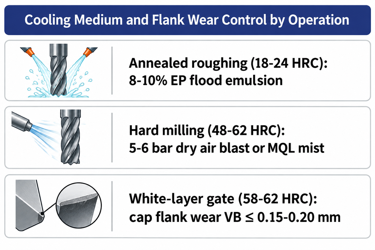
It’s critical to select the correct cooling medium in tool steel machining because an improper cooling medium can destroy an insert through thermal fatigue. Part fatigue strength can also be compromised due to an untempered white martensitic layer created by an improper cooling medium. As detailed in Seco Tools そして Modern Machine Shop hard milling guidelines, dry compressed air blast or minimum quantity lubrication (MQL) is preferred over water-based flood coolant during high-speed hard milling (50–62 HRC), while flood coolant remains common for annealed roughing and deep drilling (18–24 HRC); in interrupted hard turning, machinists avoid intermittent coolant splash that thermally shocks CBN tips. Wet coolant shatters the hot carbide edge.
When a carbide end mill cuts 58 HRC tool steel at 100 m/min, each flute reaches 700 to 850 °C during its millisecond contact arc. At that temperature, the aluminum and silicon in the PVD coating oxidize to form a microscopic, low friction Al2O3 / SiO2 thermal barrier glaze that deflects heat into the chip. Flooding the cutter with water-based emulsion quenches the flute from 800 °C to 40 °C thousands of times per minute; rapid thermal expansion and contraction open perpendicular thermal-shock comb cracks across the cutting edge, causing sudden flaking and breakage. Directing a 5 to 6 bar dry air blast at recut-prone chips removes them without thermal shock.
Equally critical is monitoring flank wear land width (VB) under ISO 3685 when finishing tool steel with high strength. Tungaloy links white-layer formation in PCBN hard turning to flank wear beyond VB = 0.15 to 0.20 mm (0.006 to 0.008 in.): the worn land raises friction and heat in the workpiece skin, which can transform and self-quench into a brittle, untempered martensitic “white layer”, with severe plastic deformation also contributing, that can initiate surface micro-cracks under cyclic die or bearing loads.
4-Gate Hard Turning & Thermal Crack Prevention Protocol
| Protocol Gate | Machining Operation & HRC State | Required Cooling & Lubrication Strategy | Surface Integrity & Tool Wear Limit |
|---|---|---|---|
| Gate 1: Annealed Roughing & Drilling | 18–24 HRC Turning, Face Milling, & Carbide Drilling | 8–10% EP semi-synthetic flood emulsion; 40–70 bar through-spindle HPC for drilling | Refractometer reading × the product’s refractometer factor ≥8% concentration; retire roughing turning inserts at VB = 0.30 mm average flank wear, the tool-life criterion ISO 3685 uses for single-point turning tests |
| Gate 2: High-Speed Hard Milling | 48–62 HRC 3/5-Axis Milling with AlTiN/TiSiN Carbide | Dry compressed air blast (5–6 bar through-spindle/nozzle) or fine MQL oil mist; zero flood coolant | Zero perpendicular comb cracks on 10x loupe check; retire end mill at VB ≤ 0.15 mm |
| Gate 3: Continuous vs Interrupted PCBN Turning | 55–62 HRC PCBN Hard Turning & Boring | Dry / air blast for interrupted cuts & heavy stock; steady high-volume flood only if thermal growth requires | Never allow intermittent coolant splash on hot PCBN or ceramic tips; use low-CBN 50% for continuous |
| Gate 4: White-Layer Prevention Gate | 58–62 HRC Bearing Races, Punches, & Sealing Faces | Cap finishing depth ap = 0.05–0.15 mm; index PCBN insert corner on fixed piece-count schedule | Flank wear ceiling VB max ≤ 0.15–0.20 mm; etched cross-section metallography for white layer, with Barkhausen noise as a supplementary screen |
Should You Use Flood Coolant or Dry Air Blast When Machining Tool Steel?
Use a flood coolant (at 8% to 10% extreme-pressure concentration) when roughly turning, drilling, or tapping annealed tool steel (18-24 HRC), to wash the heat away and prevent gummy chips from welding to the tool. Use dry compressed air blast or MQL mist when hard milling or interrupted hard turning hardened tool steel (50-62 HRC) with AlTiN/TiSiN carbide, ceramic, or PCBN tooling; flood coolant quenches the 750-850 °C cutting edge and causes thermal-shock micro-cracking.
CNC Lathe and Machining Center Selection: Box-Way Rigidity, Spindle Torque, and RFQ Checklist

Machine tool structural stiffness and dynamic damping determine whether PCBN and nano-coated carbide tools survive their rated tool life in hardened steel. In conventional positive-rake turning of mild steel, tangential cutting force (Fc) is the largest vector and passive radial thrust force (Fp) is only 0.3 to 0.5 times Fc. In negative-rake PCBN hard turning at shallow depths of cut (ap = 0.10 to 0.20 mm) with a 20° T-land chamfer, the force ratio reverses: passive radial thrust force Fp climbs to 1.5 to 2.5 times tangential force Fc in hard-turning force mechanics. Radial thrust pushes the turret back. Bed compliance triggers regenerative chatter.
To absorb that radial force vector without chatter or taper error, equipment buyers evaluating industrial CNC lathe machines for heavy alloy and hard turning and vertical machining centers focus on four mechanical specifications:
- In heavy roughing and hard turning, One-Piece Cast-Iron Slant Bed & Box-Way Damping: A high-grade HT300 Meehanite cast-iron slant bed paired with induction-hardened, ground box guideways (or heavy-preload roller linear guideways) provides hydrodynamic oil-film damping that suppresses high-frequency chatter during D2 and H13 cutting.
- At low surface speeds, a geared or high-torque spindle drive is essential: roughing annealed M2 or D2 at 50 to 80 m/min on large-diameter bar stock requires sustained low-RPM spindle torque (often via a 2-speed ZF gearbox or high-pole-count torque spindle) so the spindle does not stall under kc1.1 > 2,500 N/mm².
- At the spindle nose, Dual-Contact Taper & Low-TIR Toolholding: On machining centers, BT50 or HSK-A63 dual-contact face-and-taper spindles paired with shrink-fit or hydraulic chucks must hold total indicated runout at TIR ≤ 0.003 mm (0.00012 in.). A 0.010 mm runout error on a 0.030 mm/tooth hard-milling chip load forces one flute to carry double the load and chip prematurely.
- At the workpiece, Overhang Ratio & Workholding Stiffness: Keep internal boring bar overhang below 3×D to 4×D for steel bars, 5×D to 6×D for solid carbide bars, and up to 8×D to 10×D only with tuned mass-damped bars, combined with high-rigidity collet and chuck workholding selection that grips maximum bar length.
| Machine Subsystem | Annealed Heavy Roughing (18–24 HRC) | Hardened Finishing (55–62 HRC PCBN / Hard Mill) | Failure Risk on Under-Specified Equipment |
|---|---|---|---|
| 1. Bed & Guideway Architecture | HT300 cast-iron bed + hardened box ways | 30°–45° one-piece slant bed + box ways or size 45+ roller ways | F p /F c = 1.5–2.5 radial thrust can push the turret away and cause taper or chatter on light linear-guideway lathes, chipping PCBN |
| 2. Spindle Torque & Speed Curve | Geared 2-speed head or high-Nm low-base-speed motor | Thermally chilled 12,000–20,000 RPM VMC spindle or rigid A2-6/A2-8 lathe nose | Spindle stalls in annealed D2 roughing; axial thermal drift ruins ±0.005 mm hard tolerances |
| 3. Spindle Taper & Toolholder | BT50 / CAT50 or BMT65/VDI40 direct-mount turret | HSK-A63 / Dual-contact BT40 + Shrink-Fit or Hydraulic Chuck | Standard ER collet runout (>0.010 mm) overloads 1 flute in hard milling |
| 4. Toolholder Runout (TIR) | TIR ≤ 0.010 mm at 3×D | TIR ≤ 0.003 mm (0.00012 in.) at 3×D | Excess TIR concentrates chip load on one flute and sharply shortens hard-milling end-mill life |
| 5. Boring Bar / Cutter Overhang | Alloy steel bar ≤ 4×D | Steel ≤ 3×D; Solid Carbide ≤ 6×D; Tuned Damped ≤ 10×D | Radial bar deflection causes bell-mouthed bores and Ra > 1.6 μm chatter marks |
| 6. Coolant & Air Delivery System | 40–70 bar through-tool high-pressure pump + chip conveyor | Programmable M-code through-spindle/nozzle dry air blast (5–6 bar) + MQL | Packed hardened chips recut in deep cavities and snap solid carbide ball mills |
Whether sourcing custom tool steel components for automotive and aerospace stamping dies or specifying a new CNC turning center from a manufacturing partner, engineers should standardize the entire manufacturing process and machine inquiry with a structured technical checklist.
Buyer RFQ & Machine Specification Checklist for Tool Steel Machining
| Specification Item | Required Drawing / Equipment RFQ Callout | Acceptance & Verification Method |
|---|---|---|
| 1. ASTM Grade & Melt Route | Specify ASTM A681 (O1, A2, D2, S7, H13) or ASTM A600 (M2, M42); state ESR or PM if required | EN 10204 Type 3.1 Mill Test Report + incoming OES chemistry & annealed HBW check |
| 2. Mill Scale & Decarb Allowance | Order oversized bar/plate (≥1.5–2.5 mm per side) or pre-machined decarb-free DCF flat stock | First-pass roughing inspection confirming cleanup of hot-rolled mill bark |
| 3. Intermediate Stress Relief | Require 600–650 °C sub-critical stress relief after roughing >35% stock volume on complex dies | Furnace time-temperature chart prior to pre-quench semi-finish pass |
| 4. Pre-Heat-Treat Stock Envelope | Leave stock per side by grade and geometry per the allowance table: A2 0.20–0.35 mm; D2 and H13 0.25–0.50 mm on compact sections, up to 0.80 mm (D2) and 0.75 mm (H13) on slender shafts and plates; O1 0.50–1.00 mm on compact sections, up to 1.25 mm on slender parts | In-process pre-heat-treat CMM / micrometer travel sheet |
| 5. Target Rockwell C Window | State exact working hardness (e.g., 58–60 HRC for D2/A2; 48–52 HRC for H13) + double/triple temper | Calibrated Rockwell C (HRC) hardness test report per ASTM E18 |
| 6. Hard-Part Finishing Route | Specify whether datums, bores, and sealing faces are Low-CBN hard turned, 5-axis hard milled, or ground | Profilometer Ra / Rz report (typically Ra ≤ 0.2–0.4 μm) + CMM roundness/cylindricity |
| 7. Surface Integrity & White Layer | Enforce flank wear ceiling VB ≤ 0.15–0.20 mm; prohibit re-hardened untempered white layer or burn | Tool-life counter lock + nital etch or Barkhausen noise inspection on critical wear surfaces |
| 8. Machine Envelope & Rigidity | Match part swing, length, box-way damping, spindle Nm torque, and TIR ≤ 0.003 mm holder spec | Test-cut capability runoff on representative hardened steel blank |
Specifying tool steel cnc machining or machined parts early in process planning, for example, helps stabilize die life for subsequent production batches. Similarly, specifying precision cnc early in process planning also stabilizes die life for subsequent batches.
よくある質問frequently Asked Questions
Is 4140 considered a tool steel or an alloy steel in CNC machining?
AISI 4140 is a chromium-molybdenum medium-carbon low-alloy engineering steel (typically supplied annealed at 18–22 HRC or pre-hardened at 28–32 HRC), not a true tool steel under ASTM A681. While 4140 is employed for toolholders, bolsters and shafts, it lacks the high Molybdenum content required for the hard chromium, Vanadium, or Tungsten carbides tool steels, which are employed in cutting dies, for example.
How do I choose between 5-axis hard milling and wire EDM for hardened tool steel dies?
Choose 5-axis hard milling for 3D contoured cavities, forging dies, and blind pockets in 52–60 HRC H13 or A2 where a surface free of EDM recast layer is required. Choose wire EDM or sinker EDM for through-profiles with sharp internal corners (radii below 0.25 mm), deep narrow slots (depth-to-width above 10:1), or 62+ HRC punches.
How can machinists machine M2 and M42 high-speed steel without rapid tool failure?
Machine M2 and M42 high-speed steels in the spheroidize-annealed state (210-255 HBW) at conservative surface speeds of 45 to 75 m/min (150 to 245 SFM) using tough PVD TiAlN-coated sub-micron carbide tooling. Once hardened to 62–68 HRC, high-speed steel retains red hardness and abrasion-resistant tungsten-molybdenum carbides, so it is typically finished by grinding, including cubic boron nitride (CBN) and creep-feed grinding, or by EDM.
What is the hardest tool steel rating that can be conventionally turned or milled?
Up to 62 HRC with nano-crystalline TiSiN or AlTiN coated solid carbide end mills and up to 66 HRC with PCBN inserts and PCBN ball-nose end mills
What drawing specifications and quality documentation should buyers include when ordering custom tool steel parts?
An engineering drawing and RFQ for custom tool steel parts must specify five unambiguous parameters to prevent quoting errors and premature die failure: first, the exact ASTM A681 or A600 alloy grade (such as AISI D2, A2, O1, S7, H13, or M2) and whether raw bar or vacuum-remelted/powder-metallurgy stock is required; second, the final target Rockwell C hardness window (for example, 58–60 HRC with double or triple tempering) and case/core uniformity; third, which datum features, bearing bores, or sealing faces must be hard-turned, hard-milled, or finish-ground after heat treatment to remove quench distortion; fourth, surface roughness ceilings (Ra ≤ 0.4 μm on functional wear surfaces) and an explicit ban on untempered white-layer burn; and fifth, required inspection deliverables including EN 10204 3.1 mill certificates, furnace charts for the specified heat-treatment route, calibrated Rockwell C hardness test reports, and CMM dimensional records.
Why do dull carbide cutters cause severe work hardening in annealed tool steel?
When a worn cutting edge or an overly light feed per tooth (fz < 0.04 mm) ploughs instead of shearing, severe plastic deformation and localized friction strain-harden the annealed surface skin, spiking cutting forces on subsequent passes.
Selecting a High-Rigidity CNC Lathe or Machining Center for Tool Steel Production?
ANTISHICNC (SHANGHAI ANTS Machine Equipment) provides heavy-duty slant-bed CNC turning centers, box-way CNC lathes and vertical machining centers, engineered for high-torque annealing roughing and precision 55-62 HRC hard turning and milling. Please send us your workpiece drawings, alloy grades, and batch orders to request a CNC machine configuration and tooling from ANTISHICNC.
参考文献と情報源
- ASTM International: ASTM A681-08(2022), Standard Specification for Tool Steels Alloy (Cold-Work, Hot-Work, and Shock-Resisting Grades) そして iTeh Standards Catalog Entry.
- ASTM International: ASTM A600, Standard Specification for Tool Steel High Speed (M2, M42).
- International Organization for Standardization (ISO): ISO 3685:1993, Tool-Life Testing with Single-Point Turning Tools そして ISO 3685 Flank-Wear Reference.
- Sandvik Coromant Technical Knowledge: Turning Inserts and PCBN Grades for Hardened Steel (55–62 HRC).
- Seco Tools Application Engineering: Tips for Successful Hard Milling of Tool and Die Steels.
- Tungaloy Technical Reference: Hard Turning with PCBN Inserts, Binder Chemistry and White Layer Control.
- Cutting Tool Engineering: PCBN Turns the Hard Stuff, Low-CBN vs High-CBN Hard Turning.
- Modern Machine Shop: Hard Milling Tool Steel, Toolholding TIR, Stepovers, and Air Cooling.
- USPTO Patent Database: US6544649B1, Coated PCBN Cutting Insert for Hardened Steel Turning.
- Metallurgical & Machining Compilations: ツール スチール, High-Speed Steel, Cubic Boron Nitride, 切削加工性, Milling & Chip Thinning, Heat Treating, 、 および Surface Integrity.
Editorial & Technical Transparency Note: Reviewed by the ANTISHICNC (SHANGHAI ANTS Machine Equipment) engineering team in November 2026. Cutting speeds (m/min and SFM), feed rates, depths of cut, carbide micro-hardness spans, and pre-heat-treat stock allowances reflect published ASTM A681, ASTM A600, ISO 3685, and cutting tool manufacturer starting benchmarks. Actual cutting conditions depend on bar melt route (ingot vs PM), actual Rockwell C hardness, workholding rigidity, tool overhang and spindle torque; verify critical tool paths on a test piece prior to unattended production.