


You can use a cutting speed chart once you have translated its surface speed into a spindle speed your lathe actually produces. That’s where many systems come unglued: the chart tells you about SFM or FPM, and your machine needs RPM-but your RPM depends on your work diameter.
Use this guide as a work start-up sheet. Find your work material and tool material, step to RPM via SFM, check for agreement with your machine’s speed capability and back it off or push it up with chip analysis, tool life, vibration, coolants and finish appearance. There is no guarantee of final productivity. It only gives you a path toward a valid first cut.
Quick Specs: Turning Speed Setup at a Glance
| Chart value | Surface speed, usually shown as SFM or FPM for inch shops and m/min for metric shops |
| Lathe input | RPM, feed per rev, depth of cut, tool nose radius, coolant, and tool overhang |
| Fast formula | RPM = SFM x 3.82 / workpiece diameter in inches |
| First correction | If the cut chatters, smears, work hardens, or burns the edge, change speed and feed together |
| Machine check | Large diameters may need low RPM torque; small carbide work may need high RPM capacity |
The 5-Step Diameter-First Speed Ladder
Do not start with RPM. Start with material, tool type, and diameter. Then climb the ladder: SFM, RPM, feed, test cut, correction. At 100 SFM, a 1 inch shaft needs 382 RPM while a 2 inch shaft needs 191 RPM, so diameter decides whether the chart is gentle or aggressive.
How to Read a Cutting Speed Chart Before You Set RPM
 1")
SFM Stands for “Surface feet per minute.” That represents the speed of the workpiece, which comes across the cutting edge of a tool. On your lathe, it relates to the outer boundary of a spinning part-as size becomes less, speed also decreases as the work moves slower even if the spindle stays at a specific number.
This principle ensures that you cannot simply transpose the chart to the spindle box. When you compare turning three inches of rough bar with turning a 1 inch shaft with a finishing cut just over a third of an inch, each one has a different speed dilemma.
Read charts of cutting speed by going sequentially: Identify the general type of metal; pick the specific tool substance; evaluate the rigidity level of the machine, and; use current part dimensions-not drawing size-when calculating RPM from SFM.
Most experienced machinists repeat a phrase from every day life, and the shop floor, for good measure: formula calculation gets close, sound, chip geometry, and cutter state are your true navigators in the speed territory.
On manual lathes, start near the lower half of a range when the work sticks out far from the chuck, the toolpost is light, or the material batch is unknown. With CNC turning, constant surface speed can hold SFM more closely, but you still need a maximum RPM cap and enough jaw grip for the diameter.
Cutting Speed Chart by Material and Tool Type
 2")
Below you’ll find the recommended FPM or SFM turning values used on typical lathe set-up jobs and other relevant parameters based on assumptions in a tool chart:- Feedrate of 0.004 ipr, – Depth of cut of 0.040 inch, – Work life between regrinds or replacements of 180 minutes. We list this for reference- not as definitive parameters for any lathe.
| Material group | Examples | HSS start | Carbide start | Shop note |
|---|---|---|---|---|
| Free-machining carbon steel | 1117, 1212, 1213 | 270-290 FPM | 820-1045 FPM | Good first-test material if the lathe and tool are stiff. |
| Low carbon steel | 1006-1026 | 125-215 FPM | 800-885 FPM | Watch built-up edge when feed is too light. |
| Medium carbon steel | 1027-1052 | 55-180 FPM | 670-970 FPM | Hardness spread matters; start low if stock condition is not known. |
| Free-machining alloy steel | 4140, 4150 | 70-200 FPM | 430-685 FPM | 4140 condition can change the answer; do not ignore heat treatment. |
| Austenitic stainless | 201, 304, 304L, 321, 347 | 115-135 FPM | 570 FPM | Keep the tool cutting. Rubbing can harden the surface. |
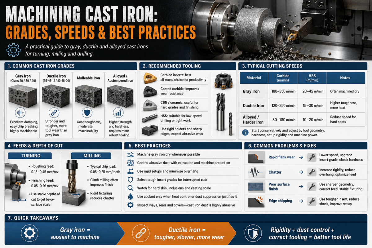
| Cast iron | Gray iron classes | 145-215 FPM | 410 FPM | Dry cutting is common, but dust control still matters. |
| Brass | Free-cutting brass | 300-350 FPM | 1170 FPM | Use suitable tool geometry; brass can grab with the wrong edge. |
| Bronze | General bronze alloys | 200-250 FPM | 715 FPM | Abrasive alloys may punish HSS faster than the chart suggests. |
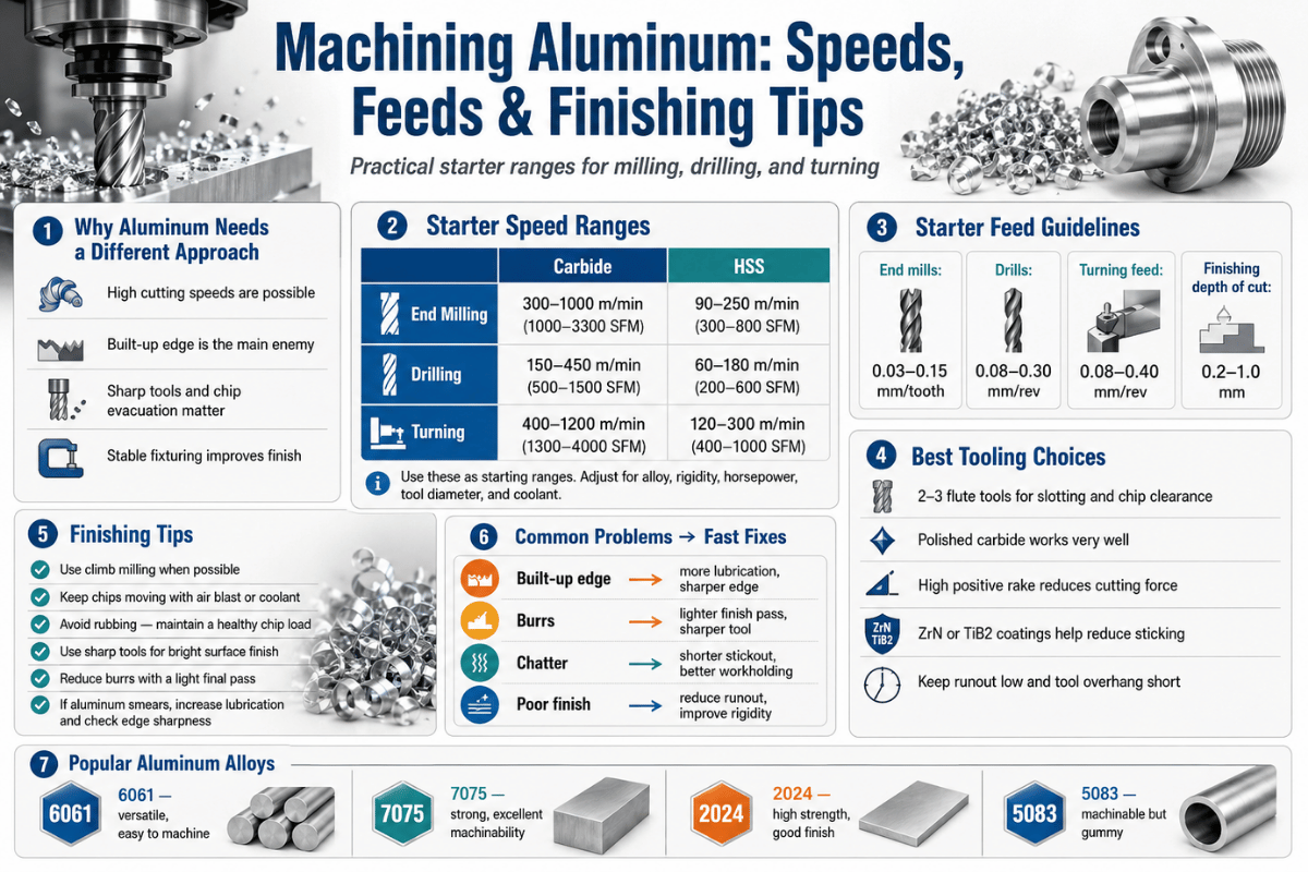
| Wrought aluminum | 5000, 6000, 7000 series | 500-600 FPM | 2820 FPM | Chip control and available RPM often limit the real setup. |
An article at the ANTISHICNC metal turning page suggests 70-135 FPM for mild steel HSS tool bits and 140-270 FPM for inserts; these values tend to favor general machinery parameters rather than ideal performance for a single tool and workpiece combination.
Convert SFM to RPM with the Diameter-First Speed Ladder
 3")
The inch version of the cutting speed calculation is: SFM = pi x diameter in inches x RPM / 12. A lot of machinists use RPM = SFM x 3.82 / diameter in inches. This 3.82 number is just 12 / pi.
Formula Card
SFM from RPM: SFM = 0.262 x diameter(in) x RPM
RPM from SFM: RPM = SFM x 3.82 / diameter(in)
Metric: m/min = pi x diameter(mm) x RPM / 1000
| Setup | Target speed | Diameter | Calculated RPM | Decision |
|---|---|---|---|---|
| HSS on steel shaft | 100 SFM | 1.000 in | 382 RPM | Good manual-lathe starting point. |
| Same steel, larger bar | 100 SFM | 2.000 in | 191 RPM | Half the RPM because diameter doubled. |
| Carbide on aluminum | 500 SFM | 0.500 in | 3820 RPM | Needs a lathe with enough high-end speed. |
| Published formula check | 2 in at 700 RPM | 2.000 in | 366.33 SFM | Matches the Mitsubishi example. |
Scenario: A machinist roughs a 2 inch 4140 shaft using HSS. Using charts for 4140/4150 materials, SFM ranges from 70 to 200 FPM. Trying a 100 SFM setting leads to a 191 RPM. If chips become blue and the tool edge wears rapidly, reduce SFM. If the chips remain stringy and the tool starts to rub the workpiece, experiment with slightly higher feed before dismissing the chart’s recommendation for SFM.
HSS vs Carbide: When the Faster Chart Number Is Not the Better Start
 4")
Carbide charts often show much higher SFM than HSS, which stands for high speed steel. That does not mean every carbide insert should run near the top of the table on every lathe. Carbide likes heat, rigidity, and enough feed to work the edge. On a springy setup, carbide can chip at a speed where a sharp HSS tool would cut quietly.
HSS Advantages
HSS holds a sharp edge longer, can work reliably on smaller or weaker machines, and functions effectively at lower surface speeds. The primary uses for this material include: small production runs, repair work, narrow shafts, non-interrupted manual operations, and cuts into materials that are unfamiliar to the operator.
Cutting speed is limited by heat. Once you heat a cutting tool to the point where its edge begins to glow red, tool life decreases exponentially.
Carbide Advantages
Carbide has the capacity for high-speed cutting and is well-suited for more abrasive materials, provided the machine, tool holder, carbide insert grade and cutting fluids were properly selected for the task.
Cutting speed is limited by support. Loose clamp assemblies, weak spindlemounts, insufficient feed rate, or excessive tool vibration could actually result in poorer overall productivity with high-speed carbide cuts when compared with optimized low-speed HSS cuts.
Scenario: Your 304 stainless steel part chatters on your small manually-operated lathe.While numerous Charts may suggest that you can run your carbide tool in a much faster SFM range than is typical for HSS tooling.In practice, when stainless steel begins to run the risk ofwork-hardening, the solution to your chatteringproblem could lie not only in the cutting speed(which should be adjusted to a lower SFM to start),but may require a sharper cutting insert, less protrusion (tool overhang) of the cutting tool, greater stability of thetool holder, consistent application of chip flow at the insert and potentially using a positive rakesemiconfigure carbide cutting tools.
Turning, Milling, Drilling, and Reaming: Why One SFM Is Not Always One Setup
 5")
Cutting speed is not the whole feeds and speeds problem. Milling cutters have teeth, chip load, radial engagement, and tool diameter. Drills trap heat in a hole. Reamers remove a small allowance and need a clean, steady feed. Turning tools cut at the outside surface of a rotating workpiece.
This is why charts often split turning, milling, drilling, and reaming even when the material is the same. Speeds-and-feeds guidance also warns that focusing only on RPM can hide a feed problem; too little chip load can create chatter even if the speed looks reasonable.
| Operation | Diameter input | Main risk | Use the chart how? |
|---|---|---|---|
| Turning | Workpiece diameter | Chatter, edge wear, poor finish | Convert SFM to RPM at current stock diameter. |
| Milling | Cutter diameter | Wrong chip load, rubbing, tool deflection | Use SFM with chip load per tooth and radial engagement. |
| Drilling | Drill diameter | Heat packed inside the hole | Start slower than open turning if chip evacuation is poor. |
| Reaming | Reamer diameter | Oversize hole, chatter marks | Use lower speed with steady feed and correct stock allowance. |
For tool selection context, see ANTISHICNC’s guides to types of cutter tools and metal cutting tools.
What Happens If Cutting Speed Is Too High or Too Low?
 6")
Bad speed choices do not show up as one single symptom. Too much speed can burn a tool, smear aluminum, or work harden stainless. Too little speed can rub instead of cut, worsen finish, and make an operator raise feed for the wrong reason.
| Symptom | Likely cause | First correction | Do not forget |
|---|---|---|---|
| Blue chips and fast edge wear | Surface speed too high for tool or coolant | Reduce SFM 15-25 percent | Check insert grade or HSS sharpness. |
| Chatter on a long shaft | Too much speed for rigidity, or feed too light | Shorten overhang, support the work, alter speed | A center or steady rest may matter more than RPM. |
| Rubbing and poor finish | Edge is not taking a real chip | Raise feed slightly or use a sharper edge | Slowing down again can make rubbing worse. |
| Stainless steel surface gets worse each pass | Work hardening from rubbing or dwell | Use a positive, sharp tool and steady feed | Do not let the tool dwell at the shoulder. |
| Aluminum builds up on the edge | Wrong geometry, speed, or lubrication | Use a polished, sharp edge and cutting fluid | More RPM without chip control can make finish worse. |
Scenario: a small aluminum part is calculated at 3820 RPM, but the lathe tops out at 2500 RPM. Do not abandon the chart. Run the highest stable speed the machine allows, choose a sharp tool, keep chip welding under control, and accept that cycle time will differ from a high-speed CNC lathe.
Match the Chart to Your Lathe Speed Range and Control Mode
 7")
A speed chart can expose a machine mismatch before purchase. If most parts are large diameter, the low-RPM torque and gearbox matter. If most parts are small aluminum or brass, the high-RPM ceiling matters. If diameters change through the cut, CNC constant surface speed can save time, but it needs a safe RPM limit.
| Lathe type | Speed range signal | Best chart fit | Internal planning link |
|---|---|---|---|
| General metal turning lathe | 70-2500 RPM | Mixed repair, shaft, and job-shop work | Metal turning lathe overview |
| Universal lathe | 40-2000 RPM | Manual training, toolroom, repair turning | Universal lathe page |
| CNC lathe | 40-6000 RPM | Small parts, constant surface speed, carbide production work | CNC lathe machine page |
| Pipe threading lathe | 20-650 RPM | Large pipe, thread cutting, slower heavy-duty turning | Pipe threading lathe page |
| Vertical lathe | 0.4-63 RPM | Large diameter work where surface speed arrives at very low RPM | Vertical lathe page |
CNC users should also understand G96 and G97. G96 holds constant surface speed as the tool moves across the part face; G97 holds fixed RPM. Near centerline, a safe maximum spindle speed is still required because a pure constant-surface-speed calculation would drive RPM upward.
For process planning, compare CNC lathes and turning centers, then review CNC turning and milling if the part needs both round and prismatic features.
Standards, Material Traceability, and the Quote Checklist
Cutting speed is not written into OSHA, ANSI, ISO, ASTM, or ASME standards as a single RPM answer, but standards still shape the decision framework around the cut. OSHA 29 CFR 1910.212 covers machine guarding for points of operation, and the eCFR version of 29 CFR 1910.212 is the legal text to check when guarding or chuck access changes. NIST SI unit guidance helps keep m/min, mm, in, and ft/min conversions consistent. ISO machine-tool categories and ASME code resources are useful references when a project moves from shop setup into documented production work.
| Traceability item | Record on the setup sheet | Decision threshold | Authority reference |
|---|---|---|---|
| Guarding and access | Chuck guard, chip shield, stop access, and bar support | Review before running 2 in bar stock above 1000 RPM or any long overhang | OSHA 29 CFR 1910.212 |
| Legal text check | Applicable OSHA / 29 CFR clause used by the safety reviewer | Use before changing guarding, fixture reach, or operator position | eCFR 29 CFR 1910.212 |
| Unit conversion | SFM, m/min, 25 mm, 50 mm, 1 in, and 2 in conversion notes | Use one unit system per setup sheet; do not mix mm and in without a written conversion | NIST SI units |
| Machine category | Manual lathe, CNC lathe, vertical lathe, or pipe threading lathe | Use the selection framework before quoting parts over 250 mm or below 25 mm diameter | ISO machine tool category listing |
| Project record | Project baseline, case study notes, production outcome, throughput, and rework rate | Record after the first 30 minutes or first 10 parts, then review before repeating the quote | ASME codes and standards portal |
This is not a claim that every turning job needs an ASTM material report or an ASME code package. It is a quote checklist. If the project requires ASTM material traceability, ANSI or ISO machine-safety review, an in-house field implementation record, or a reviewed by engineering signoff, capture that before the production outcome is judged by throughput alone.
For the unit check, write the setup values exactly: 25 mm, 50 mm, 100 mm, 250 mm, 1 in, 2 in, 4 in, 6 in, 0.004 in feed, 0.040 in depth of cut, first 30 minutes of production, 8 hr review point, 24 hr corrective-action note, and 12 months of repeat-order notes. That small habit keeps the decision matrix readable months later.
Turn the Chart into a Setup Sheet Before Production
 8")
A setup sheet keeps a chart from becoming guesswork. Write down the chart value, formula result, and first correction before the first part is cut. That makes the second part faster to set up and gives the next operator something better than memory.
Lathe Speed Setup Sheet
- Record material grade and condition, such as 4140 annealed, 304 stainless, 6061-T6, or unknown shop stock.
- Record tool material, insert grade, nose radius, rake style, and whether coolant is used.
- Record starting diameter, target SFM, calculated RPM, and machine RPM actually used.
- Record feed rate, feed per revolution, depth of cut, tool overhang, and workholding method.
- Record chip color, chip shape, sound, surface finish, and tool wear after the test pass.
- Record the final speed and feed after correction, not just the chart number.
For manual operators, ANTISHICNC’s metal lathe turning tips guide is a useful next read because speed errors often appear together with tool height, center support, and feed mistakes.
Use Cutting Speed Requirements When Choosing a Metal Turning Lathe
 9")
A lathe quote should include more than swing, distance between centers, and motor power. Bring a small speed worksheet to the buying conversation. List the largest diameter, smallest diameter, common material, tool type, and desired SFM. Then ask whether the machine can hold those speeds with the torque, chuck, and control mode the part needs.
| Buyer question | Why it matters | Evidence to bring |
|---|---|---|
| Can the spindle run slow with torque? | Large-diameter steel may calculate to low RPM but still need power. | Largest diameter, material grade, depth of cut. |
| Can the spindle run fast enough? | Small aluminum or carbide work can calculate above 3000 RPM. | Smallest diameter and target SFM. |
| Does the control support constant surface speed? | Facing and taper work can change diameter continuously. | Part drawing and maximum safe chuck RPM. |
| Will workholding survive the speed? | RPM is a safety question, not only a productivity question. | Chuck size, jaw type, bar length, support method. |
Scenario: a shop quotes both 10 inch steel flanges and 0.75 inch aluminum bushings. On the flange, a vertical lathe can make sense because the calculated RPM is low and the work is heavy. With the bushing, a CNC lathe with a 6000 RPM ceiling fits better. One chart points to two very different machines.
If you are matching a part family to a machine, start with the ANTISHICNC metal turning lathe overview, then send the material, diameter range, tolerance, and planned tool type for a speed-range check.
Outlook: Static Charts, Calculators, and CAM Tool Libraries in 2026
 10")
Static charts can be handy because they illustrate “scale” to us-the way that 4140 steel, 304 stainless and 6061 aluminum are not really in the same “speedband.” Calculators help to do this even more quickly by eliminating our chances of performing arithmetic on diameter and SFM. CAM tool library data is a much higher level of sophistication, storing notes on material, tooling, holder types, coolants, and machine tool specifications.
All three share one weak point: the first cut still needs inspection. In 2026, the best workflow is not chart versus calculator. It is chart for the starting range, calculator for RPM, setup sheet for traceability, and operator correction for the real machine.
FAQ
What is the optimal cutting speed?
The optimum cutting speed is that surface speed where acceptable tool life, effective chip control, appropriate heat level and acceptable surface finish can be achieved in specific machines. Any chart that you find provides only a guideline; speed will vary based on material conditions, tool design, fixture style, coolant type, and the inherent rigidity of your lathe tool holder and the machine tool itself.
How do you calculate cutting speed from RPM?
The formula for surface speed (SFM = Surface Feet Per Minute) is SFM = 0.262 x diameter in inches x RPM. For metric it becomes (m/min = pi x diameter in mm x RPM / 1000). A typical example can be seen by looking up the value of SFM: 2” diameter, 700 RPM and ~366.33 SFM. But you can reverse the process too-take a SFM value from your chart and determine the spindle RPM using this equation: RPM = SFM x 3.82 / diameter in inches.
What happens if cutting speed is too high?
With increasing tool temperatures, edges become dulled; the chip can be torn instead of cleanly fractured and your finished surface can become smudged and smeary. Stainless steels can be difficult to cut once their surfaces have “work hardened” from dwell or rubbing conditions. Slow the spindle Speed Down with moderate decreases.
What is the cutting speed for 4140 steel?
For high-free-machining alloy steels such as 4140 and 4150, a common turning chart might suggest 70-200 FPM for HSS tools and 430-685 FPM for carbide. If you are working with 4140 and your material appears hardened, the setup might be less rigid, or you will be doing interrupted cuts, start towards the lower end. Let’s calculate a 2” diameter bar at 100 SFM. 100 SFM = 0.262 x 2” x RPM so 100 = 0.524 x RPM; or RPM=100/0.524=190.8. And on the 1” diameter bar: RPM=100/(0.262*1) = 381.7.
What is a safe cutting speed for aluminum?
And for wrought Aluminum (5000, 6000, 7000 series material) the same chart calls out 500-600 FPM for HSS and 2820 FPM for carbide. Notice what those values are likely to require in terms of spindle RPM and the necessity for machine speed, as well as good chip forming characteristics.
Is carbide always faster than HSS?
While many materials are well suited to faster cutting with Carbide, it isn’t wise to launch your setup into the higher carbide SFM unless conditions warrant.
Is surface speed the same as spindle speed?
No. Surface speed is how fast the material moves past the cutting edge. Spindle speed is the RPM of the chuck or spindle. Diameter connects them. At the same RPM, a 2 inch diameter has twice the surface speed of a 1 inch diameter.