


On mechanical drawings, ISO 2768 is the worldwide standard for applying general tolerances to linear and angular sizes where no individual dimension tolerance has been specified. Instead of specifying a deviation adjacent to the 200 dimensions on a part drawing, an engineer makes one short callout (such as “ISO 2768-mK”) and the standard fills in the rest of the necessary information. In this brief guide you’ll learn what ISO 2768 is, how to read all 4 classes of tolerance, how to decipher individual values on a ISO 2768-generated chart, and even what two-letter codes like mK and fH mean. Bonus: one surprising fact that many reference pages leave out – a section of ISO 2768 has already been superseded, and a new 2026 edition is coming down the pipe!
Quick Specs: ISO 2768 at a Glance
| Standard parts | ISO 2768-1 (linear & angular) + ISO 2768-2 (geometric) |
| Linear/angular classes | f (fine), m (medium), c (coarse), v (very coarse) |
| Geometric classes | H, K, L |
| Typical drawing callout | ISO 2768-mK or ISO 2768-fH |
| Units | mm (degrees and minutes for angles) |
| Current status (2026) | 2768-2 replaced by ISO 22081:2021; 2768-1 being re-issued as ISO 2768 Edition 2 |
What Is ISO 2768?
 1")
Fundamentally, ISO 2768 is a general-tolerance standard, providing the accepted range of variations that apply to any dimension on a drawing for which no explicit tolerance has been written. Its principal function is to limit the complexity of drawing documentation. A designer applies tight controls only to those features that are critical for part-to-part assembly, thereby using a single general-tolerance instruction to define all other less-important values. The ISO 2768 applies specifically to part-to-part assembly as it is to be held with parts made by machining and by sheet metal forming processes.
These controls aren’t a clerical shortcut for the designer, they’re a major economy for the shop. Every tolerance on a drawing is a tolerance that must be inspected and passed to ensure part-to-part interchangeability. WHY IS THAT A LIABILITY – Because the cost associated with every tight tolerance expands dramatically with any additional specified values. SO WHAT – By allowing standard tolerances for, for instance, the 90% of non-critical dimensions, you save significantly on inspection costs while also controlling any critical dimensions that would impede the successful and efficient assembly of your parts.
You might have seen the ISO 2768 specification on drawings referenced as ISO 2768, DIN ISO 2768, and EN ISO 2768. All of these reference the identical technical text, adopted by various international standards bodies-namely, the DIN for Germany and the EN for all of Europe (following ISO standards). One comment on Reddit from an experienced designer suggests that in Switzerland, the ISO 2768 standard is commonly applied for its direct correlation of length-dependent tolerances to the ability of a machining shop, wherein shorter dimensions carry tighter specifications and larger dimensions get a looser range of permissible variations, automatically.
With one simple line callout, a ISO 2768 standard acts as a full set of controls for any toleranced dimension, resulting in far fewer call-outs, quicker inspection times, and reliable parts.
ISO 2768-1 vs ISO 2768-2: What Each Part Covers
 2")
A quick caveat: previously the standard was split between two parts, and it is very common for designers to confuse the two. ISO 2768 part 1 covers both linear and angular sizes, and this includes all dimensions: such as lengths and diameters of features; radii of fillets and grooves; chamfers; and angular specifications. Part 2 addresses all geometrical features that do not have any explicit dimension defined, such as straightness, flatness, perpendicularity, symmetry, and circular run-out. A drawing indicating control for both type 1 and type 2 values would clearly specify, and therefore indicate that the specification should be interpreted from, both Parts of ISO 2768 with dual character callouts.
| Feature | ISO 2768-1 | ISO 2768-2 |
|---|---|---|
| Controls | Linear & angular dimensions, radii, chamfers | Geometric: straightness, flatness, perpendicularity, symmetry, run-out |
| Tolerance classes | f, m, c, v (4 classes) | H, K, L (3 classes) |
| Letter case in callout | lower-case (m) | upper-case (K) |
| 2026 status | Re-issued as ISO 2768 Edition 2 | Replaced by ISO 22081:2021 |
When reading “2768-mK” the lower case m indicates the Part 1 size class and the upper case K indicates the Part 2 geometry class. In this way, the first question searchers commonly have is answered head-on: size vs. geometry control. But the key come in how those two letters get combined – this is arguably the single most important takeaway to understanding the standard.
The Four Tolerance Classes: Fine, Medium, Coarse, Very Coarse
 3")
The Part 1 contains four grades of tolerance; most accurate to least accurate are f (fine), m (medium), c (coarse), v (very coarse). In each of these grades you’ve a tolerable deviation which increases with increasing size of a feature, which of course makes intuitive sense for a machinists since there’s an easier job in holding a 2 mm device with tolerance as holding a 2 m device, and for your needs the grade chosen represents an obvious compromise between economy and accuracy.
There’s a design decision that causes a great many problems: not tighter, but dearer. Giving a “f” when a part only need “m” can more than double, triple your inspection work, and will reject some good parts that would work fine. Here’s another one from practice (from the floor): start with an “m” (medium) as your standard for general machined parts. Change to “c” for flame-cut blanks and weldments.Only use an “f” on the places that the part is really going to fit together with another part.
- One note replaces dozens of individual callouts
- Length-dependent bands match real process capability
- Faster drawing creation and faster inspection sign-off
- Shared language between design, shop, and supplier
- Doesn’t cover position / true position, needs explicit GD&T
- Over-tight class raises scrap and inspection cost
- Part 2 geometric classes are now superseded by ISO 22081
- Not a substitute for fit tolerances such as H7/g6
Decoding ISO 2768 Designations: The Two-Letter Rule (mK, fH, cL)
 4")
When you learn that Part 1 uses lowercase letters and Part 2 uses uppercase letters, each label deciphers in just the same way. Label it the Two-Letter Rule: The first (lowercase) letter is the size class from Part 1, and the second (uppercase) letter is the geometry class from Part 2.
The full callout using a dash: ISO 2768-mK. the m choosing medium linear/angular tolerances of ISO 2768-1 and K choosing medium geometric class of ISO 2768-2, should be placed into title block area or on a title block face. Usually sheet metal components may be drawn to ISO 2768-mK while turned components may be drawn to ISO 2768-fH.
Common combinations decode like this:
- ✔mKmedium size + class K geometry (general sheet metal)
- ✔fHfine size + class H geometry (precision machined parts)
- ✔mHmedium size + tight class H geometry
- ✔cLcoarse size + loose class L geometry (weldments, structural)
When applied to a drawing you need both letters; ISO 2768-mK is a valid callout, and note the dash between 2768 and the classes.
ISO 2768 Tolerance Charts: The Full Value Tables
 5")
This is what engineers are actually looking for these days. Every value is an acceptable tolerance, unless stated, in mm, extracted from the ISO 2768-1 (linear, radius/chamfer, angular) and ISO 2768-2 (geometric) tables. First, locate your nominal size range from the left column, and then go across to your class.
Linear dimensions, permissible deviations (±mm)
| Nominal length (mm) | f (fine) | m (medium) | c (coarse) | v (very coarse) |
|---|---|---|---|---|
| 0.5 up to 3 | ±0.05 | ±0.1 | ±0.2 | — |
| over 3 up to 6 | ±0.05 | ±0.1 | ±0.3 | ±0.5 |
| over 6 up to 30 | ±0.1 | ±0.2 | ±0.5 | ±1.0 |
| over 30 up to 120 | ±0.15 | ±0.3 | ±0.8 | ±1.5 |
| over 120 up to 400 | ±0.2 | ±0.5 | ±1.2 | ±2.5 |
| over 400 up to 1000 | ±0.3 | ±0.8 | ±2.0 | ±4.0 |
| over 1000 up to 2000 | ±0.5 | ±1.2 | ±3.0 | ±6.0 |
| over 2000 up to 4000 | — | ±2.0 | ±4.0 | ±8.0 |
External radius & chamfer heights, permissible deviations (±mm)
| Nominal size (mm) | f | m | c | v |
|---|---|---|---|---|
| 0.5 up to 3 | ±0.2 | ±0.2 | ±0.4 | ±0.4 |
| over 3 up to 6 | ±0.5 | ±0.5 | ±1.0 | ±1.0 |
| over 6 | ±1.0 | ±1.0 | ±2.0 | ±2.0 |
Angular dimensions, permissible deviations
| Shorter side length (mm) | f | m | c | v |
|---|---|---|---|---|
| up to 10 | ±1° | ±1° | ±1°30′ | ±3° |
| over 10 up to 50 | ±0°30′ | ±0°30′ | ±1° | ±2° |
| over 50 up to 120 | ±0°20′ | ±0°20′ | ±0°30′ | ±1° |
| over 120 up to 400 | ±0°10′ | ±0°10′ | ±0°15′ | ±0°30′ |
| over 400 | ±0°5′ | ±0°5′ | ±0°10′ | ±0°20′ |
Geometrical tolerances- ISO 2768-2, classification H / K / L (mm)
| Feature / range (mm) | H | K | L |
|---|---|---|---|
| Straightness/flatness, up to 10 | 0.02 | 0.05 | 0.1 |
| Straightness/flatness, 30 up to 100 | 0.1 | 0.2 | 0.4 |
| Straightness/flatness, 300 up to 1000 | 0.3 | 0.6 | 1.2 |
| Perpendicularity, up to 100 | 0.2 | 0.4 | 0.6 |
| Perpendicularity, 300 up to 1000 | 0.4 | 0.8 | 1.5 |
| Symmetry, up to 100 | 0.5 | 0.6 | 0.6 |
| Circular run-out (all sizes) | 0.1 | 0.2 | 0.5 |
Is 0.05 mm a Good Tolerance?
At small scale, 0.05 mm represents a tight and high quality tolerance – for any length less than or equal to 6 mm on the ISO 2768-1 table it falls into the fine (f) class. It’s the smallest band offered by the general-tolerance table, and while a surface grinder or wire EDM is likely to achieve this it’s at the outer edge of what casual milling will hold. Whether it’s “good” depends on context; for a bearing bore this is still too loose (you’d use a specific fits table, say H7), but for a bracket clearance hole, it’s over-engineered. (To put it in perspective, a 0.05 mm tolerance on a 50 mm feature would be tighter than what the fine class allows – 0.15 mm – so always compare the tolerance to the nominal size.)
How to Apply ISO 2768 on a Drawing
 6")
Once you know where to get it, applying the standard takes about five minutes: add a general tolerance note next to, or inside, the title block such as “General tolerances ISO 2768-mK”, and all dimensions which do not have an explicit tolerance called out automatically take on values from the tables above. Items requiring higher precision, or a specific interference fit, will still have explicit tolerances noted alongside them, which override the general note for that dimension only.
- Decide the size class: medium (m) for general machining.
- Decide the nature of your work – is it general-purpose K, or precision H?
- Write the combined note: ISO 2768-mK (mind the dash).
- Tolerance the critical features individually; they override the note.
- New drawings should take their geometrical cues from ISO 22081 (see below).
Don’t mistakenly assume a general tolerance note addresses position, profile, or datum features – true, controlled position still requires explicit GD&T (ISO 1101). The general notes are the lowest floor for boring-out dimensions, not the definition for functional geometric control.
ISO 2768 vs Real Process Capability: Grinding, CNC, Turning & EDM
 7")
Tolerance classes are meaningless unless your processes can hit them. Before quoting work for a ISO 2768-fH part, ensure that the processes you’ve selected for its fabrication are actually capable of holding the fine class; the figures in the below table represent the general capabilities cited by various industry machining guides, though specific machine tool rigidity, fixturing capabilities, and part complexity should always be considered as contributing factors.
| Process | Typical achievable (±mm) | Comfortable ISO 2768 class |
|---|---|---|
| Surface / cylindrical / centreless grinding | ±0.005–0.025 | f (fine) and tighter |
| Wire EDM | ±0.0025–0.05 | f (fine) and tighter |
| CNC milling / turning | ±0.025–0.125 | m (medium), f on small features |
| Conventional mill / lathe | ±0.1–0.2 | m to c |
| Laser cutting | ±0.1 | c (coarse) |
| Waterjet / plasma | ±0.1–1.0 | c to v |
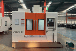
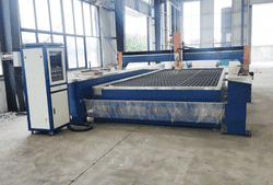
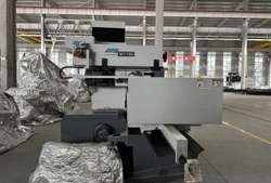
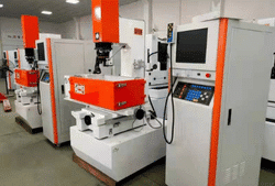
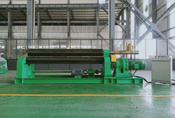
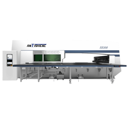
Think of this table as a map: if your drawing specifies the fine class, the work clearly isn’t being done on a flame table, but on precision metal grinding equipment or a wire EDM machine. A surface grinder produces flat datums, while round seats and shafts are finished on a CNC cylindrical grinder or by centreless grinding. A CNC lathe machine and a vertical machining center excel at medium-accuracy, higher-volume production. Coarse and very-coarse pieces from laser cutting and waterjet cutting machines are the reason sheet-metal drawings often reference the less-stringent mK class instead of fH.
What Machining Process Holds the ISO 2768 Fine Class?
Grinding and wire EDM are the reliable paths to fine (f) class. Surface, cylindrical, and centreless grinding regularly accomplish 0.005-0.025 mm, well inside the 0.05 mm fine range at small sizes, and they also give the surface finish that fine-class parts usually want. Wire EDM gets 0.0025-0.05 mm and is the route for hardened tool steel or complicated profiles. CNC milling and turning can hit the fine class on small, stiff features, but as length rises the achievable range broadens, so a long fine-class dimension is safer territory for grinding than for one milling pass.
How ISO 2768 Relates to GD&T, ISO 1101 and ISO 286 Fits
 8")
Default tolerances overlay the whole of the tolerancing system; they’re the top layer, not the end in themselves. They ‘layer underneath’ three other tools you’ll encounter on the same drawing. Being aware of where the function goes turn up would otherwise lead both to under-SPECifying and the high cost of GD and T-dominates-every where.
| Standard | Role | When it overrides ISO 2768 |
|---|---|---|
| ISO 1101 (GD&T) | Explicit geometric control: position, profile, datums | Any feature with a feature-control frame |
| ISO 286 (fits) | Hole/shaft fits such as H7, g6, H7/g6 | Any mating diameter with a fit code |
| ISO 22081 | General geometric & size specifications (GPS) | New drawings replacing ISO 2768-2 defaults |
In characteristic the hierarchy is simple: an explicit tolerance trumps a fit code trumps GD and T-by default trumps the ISO 2768 general note. A diameter marked “25 H7” disregards the general tolerance altogether; a hole with a position frame is covered by ISO 1101; everything else falls to your mK or fH note. A common trap is to leave a critical fit to the general tolerance – 0.2 mm medium on a 25 mm bore is much too slack for a press fit expecting roughly an H7 band of +0.021/0 mm.
Is ISO 2768 Obsolete? The ISO 22081 and 2026 Update
 9")
Here is the part that most each reference chart gets wrong. ISO 2768 is not a dead standard – but it is changing fast, and the two elements are going in opposite directions. If you learn only one thing from this guide, make it this.
Part 2 of the standard, ISO 2768-2:1989, has been withdrawn. It was cancelled and replaced by ISO 22081:2021, which now specifies general size and geometrical attributes within the current GPS structure (referring to ISO 8015). Any new drawings requiring default straightness, flatness, perpendicularity, symmetry, or run-out should now reference ISO 22081 rather than the old Part 2 H/K/L classes.
ISO 2768-1:1989 (linear & angular) is being re-issued, not set aside. An updated single-part ISO 2768 Edition 2 hit the “pre-publication” point (60.00) on 2 June 2026, devised by technical committee ISO/TC 213. Its new name – “Geometrical product specifications (GPS) – Dimensional tolerancing – Tolerance limits for general specification of linear and angular sizes” – displays that the linear/angular issues are being integrated into the GPS system, and it will take the place of ISO 2768-1:1989 after publication.
If you are drafting in 2026, continue to draft ISO 2768-1 for linear and angular general tolerances, but use ISO 22081 for geometric defaults rather than ISO 2768-2, and keep an eye out for the ISO 2768 Edition 2 release so your title-block note remains current. Current drawings referring to ISO 2768-mK are still available to view – but the tolerances have not altered – but the geometric section now points to a superseded part.
So to honestly answer ‘is ISO 2768 obsolete?’ the answer is no: half of it has been successfully redesigned as ISO 22081, the other half is slated for a 2026 rewrite under the same name. And in fact the whole idea of general tolerance is even more strongly embedded than before into the GPS ecosystem.
Frequently Asked Questions
What is ISO 2768 used for?
View Answer
What does ISO 2768-mK mean?
View Answer
Is ISO 2768 the same as DIN 2768?
View Answer
Which class applies if no tolerance class is specified?
View Answer
Is ISO 2768 obsolete in 2026?
View Answer
Does ISO 2768 apply to plastics or 3D printing?
View Answer
ANTISHICNC supplies precision grinding, turning, milling, and EDM machine tool capabilities that routinely meet the fine class limits for ISO 2768 to be machined under production conditions. Selecting the correct production method to match the specific class before quoting helps ensure profitable part manufacturing.
About This Guide
As we produce machine tools that build high-precision metal parts, the specific ISO 2768 tolerances shown are associated with the machine tools that have these capabilities-including grinding for the fine class, wire EDM for profiles, and machining for the medium classes. The listing of standards and dates was recently verified with ISO’s catalogue to determine status and upcoming updates, such as the replacement of ISO 2768-2 with ISO 22081, and the ongoing work on ISO 2768 Edition 2 due in 2026.
References & Sources
- ISO 2768-1:1989, General tolerances, Part 1International Organization for Standardization
- ISO 2768-2:1989, General tolerances, Part 2International Organization for Standardization
- ISO 2768 (Edition 2, under publication 2026)ISO/TC 213, Dimensional and geometrical product specifications
- ISO 22081:2021, Geometrical product specifications (GPS) — General geometrical specificationsInternational Organization for Standardization