


Updated June 2026 · Reviewed by the ANTISHICNC technical team
CNC workholding is the set of vises, soft jaws, fixtures, chucks, and modular systems that locate and hold a workpiece against cutting forces while a machine cuts it. Get it wrong and even a perfect toolpath produce scrap, most dimensional errors start at the fixture, not the spindle. This guide cover every common workholding method, shows you how to size clamping force with a worked example, and gives you a decision matrix for picking the right setup on your CNC milling machine.
In short: CNC workholding does two jobslocating a part (fixing all six degrees of freedom with the 3-2-1 principle) and clamping it (holding it against cutting forces). The best method depend on part shape, tolerance, and production volume: vises and soft jaws cover most prismatic work, fixtures and zero-point systems win on repeatable production, and vacuum or magnetic chucks handle thin, flat parts that mechanical clamps would distort.
Quick Specs: Workholding at a Glance
| Clamping-force rule of thumb | ≥ 2× the resultant cutting force when friction alone holds the part |
| Locating principle | 3-2-1 (6 contact points lock 6 degrees of freedom) |
| Tooling-plate repeatability | ~0.0005 in (half a thousandth) with dowel pins |
| Zero-point repeatability | < 0.002 mm (single-digit micron) |
| Zero-point setup-time cut | up to 90% vs. align-and-bolt |
| Vacuum hold-down | 14.7 psi max × sealed area (atmospheric pressure) |
What Is CNC Workholding?

CNC workholding is any apparatus that secures and positions a workpiece during machining. It splits into two distinct jobs that machinists often blur together: locating the part (defining exactly where it sits) and clamping it (holding it there against cutting forces). Crank a part down hard and it can still sit in the wrong place, clamping force doesn’t define position, locators do.
What’s the difference between workholding and clamping?
Workholding is the whole system, locators, supports, and clamps. Clamping is just the force that hold the part against those locators. Any rigid body has six degrees of freedom: three translations and three rotations. Effective workholding must constrain all six. Standard engineering practice is the 3-2-1 locating principle: three points establish the primary datum plane (locking Z translation plus rotation about X and Y), two points define a secondary plane (locking one horizontal direction plus rotation about Z), and one point lock the final degree of freedom. Six contact points fully constrain the part without over-constraining ita documented heuristic in academic fixture design research and modular fixturing studies at UC Berkeley.
Always constrain the part with locators first, then apply clamping force into those locators — never use the clamp to pull the part into position. Any clamp that defines location will shift the part every time torque varies. Locate, seat, then clamp: that order is what makes a setup repeatable.
The Main Types of CNC Workholding

Most shops reach for one of six workholding families. Picking wrong is expensive: an over-built fixture wastes setup hours, while an under-built one lets the part slip and scraps the blank, and the risk climbs because resultant cutting forces can jump 30% or more as depth of cut increases. Whether you need a quick clamping fixture or full modular workholding, this table compares them on rigidity, setup speed, and the parts each suits best, use it to shortlist two or three options before you open CAM. Academic fixturing research (Iowa State) frames the same trade-off: a workholding method must fully constrain the part while leaving the cutting zone open to the tool.
| Workholding type | Rigidity | Setup speed | Best for | Main limitation | |
|---|---|---|---|---|---|
| Machine vise + soft jaws | High | Fast | Prismatic parts, low–medium volume | Can warp thin or oversized parts | |
| Chucks & collets | High | Fast | Round stock, small repeated parts | Round/symmetric geometry only | |
| Step & toe clamps | Medium–High | Slow | Large plates, odd shapes | Not repeatable after release | |
| Custom / modular fixtures | Very High | Fast (after build) | Medium–high volume, repeat runs | Upfront design and build cost | |
| Vacuum / magnetic | Low–Medium | Fast | Thin, flat, finished-surface parts | Limited holding force on heavy cuts | |
| Zero-point / quick-change | High | Very Fast | High-mix, frequent changeovers | Interface and base-plate cost |
Rigidity and setup-speed bands synthesized from peer-reviewed and trade-press machining sources.
Vises, Soft Jaws, Chucks, and Collets

On a CNC mill, the machine vise is the default workholding device, and for good reason, a properly trammed vise is rigid, fast, and extremely repeatable. Its sweet spot is the catch: a vise can only open so far, and a thin part will bow when you tighten the jaws. For anything that isn’t a clean rectangular block, the answer is soft jawsaluminum (or steel for long runs) jaw blanks you machine to match your part’s profile. They let a vise grip round, angled, or irregular parts while protecting finished surfaces.
Machinists on Practical Machinist commonly cut the soft-jaw pocket about 1/16 in smaller than the vise opening and add tapped end stops so every part re-locates in the same spot. Machine the form in the flipped (180°) orientation with a spacer between the jaws, and torque both the jaw bolts and the vise to spec — inconsistent torque is a top cause of part-to-part variation across a batch.
The same precise, repeatable seating studied in UC Berkeley fixturing research applies to soft jaws: a located seat beats brute clamping force every time. Round parts call for chucks and collets. A 3-jaw chuck or a bank of collet chucks bolted to the table hold round stock for milling, and collets shine when you’re running many small parts. Expanding collets, mandrels, and arbors take this further: drop an expanding cylinder into a bore on the underside of the part and lock it, and you can reach the workpiece from every direction except the bottom, no clamp in the cutter’s way.
Custom and Modular Fixtures

When a vise can’t hold the part, or when you’re running enough volume that setup time dominates cost, it’s time for a fixture. The common mistake here is building a custom fixture too early: below roughly 50 parts the build hours rarely pay back, because a machined fixture can take 4 to 8 hours of design and cutting before it holds its first part to tolerance. Milling fixtures earn their keep on repeat runs, not one-offs. Its foundation is usually a fixture plate (tooling plate): an aluminum, cast-iron, or steel plate with a grid of holes alternating between precision dowel-pin bores and threaded mounting holes. Dowel pins give repeatable location to roughly half a thousandth (0.0005 in), while the threaded holes bolt down your part or a custom sub-fixture.
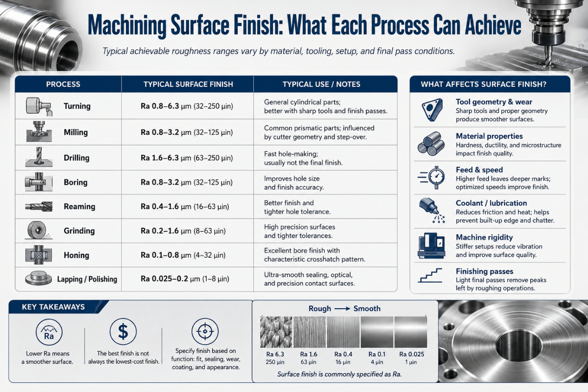
Dedicated fixtures hold one part and deliver the highest rigidity and shortest cycle times, worth it at high volume. Modular fixtures reconfigure from standard components on the same grid, trading a little rigidity for flexibility across small batches. Once the fixture is built, repeat runs are where the money is: build cost is fixed, but every reorder rides the same setup. This is also a good place to think about your broader process, fixture rigidity feeds directly into achievable machining surface finish and into the feeds and speeds you can safely run.
Build fixtures around a 3-2-1 dowel-pin layout: two pins set the primary location, a third sets orientation, and the threaded grid handle clamping. Keep clamp points over solid, supported material, never over an unsupported span, and keep overhangs short to limit deflection. A standard fixture plate grid lets you reconfigure a machine for a different job in 5–10 minutes instead of dialing in from scratch.
Power Workholding: Hydraulic, Pneumatic, Magnetic, and Vacuum

When hand-cranked clamping can’t keep up, high part counts, automation, or parts that mechanical jaws would distort, power workholding takes over. A common mistake is reaching for magnetic workholding on a non-ferrous part, where it simply fails to hold; another is trusting vacuum on a heavy roughing pass, where the part can break loose because hold-down is capped by sealed area. Hydraulic and pneumatic clamps fix the repeatability problem by delivering the same machined-in clamping force, often 5 to 25 kN, on every cycle without operator variation. Patented power-clamping designs such as US 6,768,076 B2 are built to draw components together with controlled pressure rather than brute force. Hydraulic and pneumatic clamps apply consistent, repeatable force at the push of a button, ideal for production cells and unattended running. Magnetic chucks hold flat ferrous parts with even, distortion-free pull. Vacuum fixtures use atmospheric pressure: at sea level, 14.7 psi pushes down on every square inch of sealed area, so large thin sheets stay flat without a single clamp touching the top.
Is vacuum workholding a replacement for mechanical fixtures?
No, and this is a common misconception. Vacuum and magnetic systems are assistive: they excel on thin, flat, or surface-sensitive parts but give up holding force on heavy roughing cuts. Vacuum hold-down is capped by sealed area times 14.7 psi, so small parts with little surface area pop off when cutting forces exceed that limit. Magnetic chucks don’t work on aluminum or other non-ferrous metals at all. For heavy material removal or irregular parts, mechanical or custom fixtures are still required, the power method supplements them, it rarely replaces them.
Zero-Point and Quick-Change Systems

Zero-point clamping is the fastest-growing idea in workholding, and it attacks the most expensive part of high-mix machining: setup. The problem it solves is real money, because every minute spent re-indicating a fixture is a minute the spindle isn’t cutting, and on a precision job a rushed re-clamp risks scrap from a lost datum. A zero-point system is a standardized quick-change interface, a receiver (clamping pot) in a base plate and a retention stud on the workholding, that links the machine table, fixture, and workpiece to one defined reference. Once a setup is dialed in, you can pull it off the machine and return it with repeatable location, so setup work happens off-spindle while the machine keep cutting.
Those numbers are why shops adopt it. According to Modern Machine Shop, zero-point systems deliver setup-time reductions of up to 90% when they replace repeated align-and-bolt steps with a single locate-and-clamp action, with clamping forces from roughly 12.5 to 60 kN per unit and around 0.0001 in repeatable location. One profiled shop cut part-to-part time by more than 50% and reached full ROI in under six months. Academic work in CIRP-published research on clamping systems reports modular zero-point systems holding positional repeatability below 0.002 mm. This interface is patented territory too, see, for example, quick-change mounting systems like US 8,708,323 B2.
Workholding for 5-Axis and Multi-Axis Machining

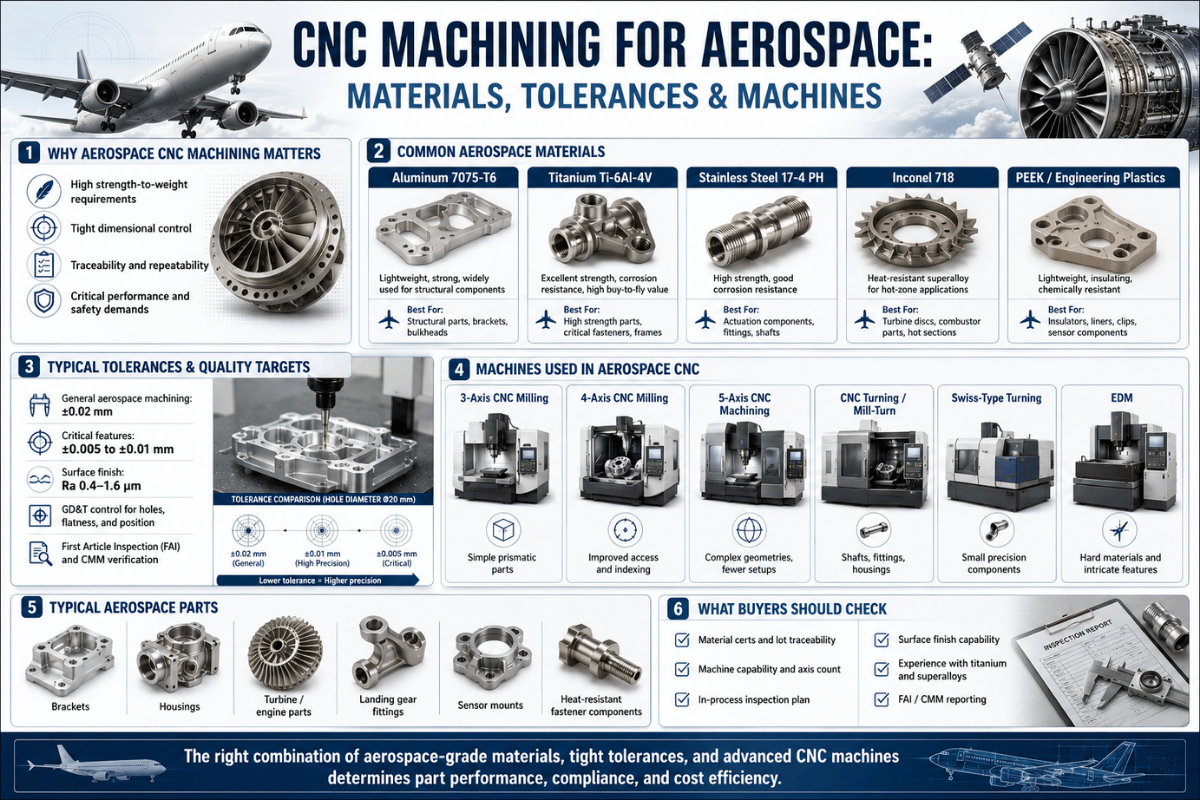
Five-axis and multi-axis work flips the workholding problem: now the tool can reach almost any face, so the challenge is holding the part securely while keeping the workholder out of the cutter’s path. Standard answers are dovetail fixtures (which grip a small machined dovetail tab, exposing five sides), tombstones (multi-face columns on horizontal machining centers that load many parts per cycle), and risers/trunnions that lift the part into the work envelope. Dovetail and serrated jaws grip in two or three directions at once, which is how a CNC gets away with holding only a thin tab of stock. Multi-axis access also pairs naturally with a live tooling lathe when you want to cut setups further, and it’s standard practice in demanding work like aerospace CNC machining.
How to Calculate Clamping Force (and Avoid Distortion)

Clamping force has to clear two bars at once: high enough to beat the cutting force, low enough not to deform the part. University fixture-design criteria (Oklahoma) set exactly this goal — constrain the part against machining loads without inducing distortion. Here’s how to size it, then a worked example you can copy with your own numbers.
When friction alone holds the part, required clamping force ≈ (cutting force × safety factor) ÷ friction coefficient. As a floor, design for at least 2× the resultant cutting force — then verify the part won’t yield under that load.
Friction-only setup. Say a side-milling pass produce a resultant cutting force of about 400 N. Dry steel-on-steel friction is roughly µ = 0.15, and we want a safety factor of 2 for vibration and tool-load swings. Friction must resist the cut, so µ × Fclamp ≥ Fcut × SF, which gives Fclamp ≥ (400 × 2) ÷ 0.15 ≈ 5,300 N (about 1,200 lbf). That’s a lot of force for a small cut, because friction is a poor way to resist machining loads.
Add a fixed stop and the math changes. Put a solid locator behind the part so the stop, not friction, takes the cutting thrust. Now the clamp only has to fight lift and vibration, and the required force drop by several times. In a published free-body example, an 1,800 lbf cut reacted against a stop needs only about 1,290 lbf of clamp force; applying a 2:1 safety factor lands at roughly 2,580 lbf, far less than friction alone would demand for the same cut.
This is exactly why The Locate-Then-Clamp Sequence matters: a locator that absorbs the cutting load let you clamp lighter, which protects thin walls from distortion.
Over-clamping is the flip side. On thin-wall parts, excess force is a leading cause of dimensional error: the wall deflects under the clamp, you machine it “flat,” and it springs back out of tolerance when you release it, so more force makes accuracy worse, not better. Distribute the load over a wide area, use soft jaws or supports, and reach for torque-controlled or hydraulic clamps when consistency matters. Tight tolerances such as ±0.01 mm depend on this as much as on spindle accuracy.
How to Choose the Right Workholding

The right workholding solution falls out of three inputs: part shape, production volume, and tolerance. This matrix maps the first two to a recommended starting point, then sanity-check it against your tolerance and tool-access needs. For high-mix shops, quick-change selection echoes patented interface design like US 8,708,323 B2, which standardizes how varied workholding mounts to a single base.
| Part type | One-off / prototype | Batch (10–500) | High volume | |
|---|---|---|---|---|
| Prismatic block | Vise | Vise + soft jaws | Dedicated fixture / tombstone | |
| Round / cylindrical | Chuck | Collet chuck bank | Collet + 4th axis | |
| Thin / flat plate | Step clamps | Vacuum fixture | Vacuum + zero-point base | |
| Irregular / organic | Soft jaws / tabs | Custom fixture | Dedicated fixture | |
| Many small parts | Vise pallet | Modular fixture plate | Pallet pool / zero-point |
- Decide how you’ll hold the part first, locking it in after programming forces you to compromise access or accuracy.
- Map datums and supported surfaces; keep clamps clear of the toolpath.
- Minimize re-clamps; every reset adds positional error.
- Over-clamping thin walls → spring-back and scrap.
- Inconsistent jaw/vise torque → part-to-part drift.
- Relying on friction instead of a locator → needing huge clamp force.
Industry Outlook: Automation and Zero-Point Growth

What’s reshaping workholding most isn’t a new clamp, it’s labor and machine economics. A persistent skilled-labor shortage plus the shift to high-mix, low-volume production means shops can no longer afford spindle hours lost to manual align-and-bolt setups. That’s the real driver behind zero-point and pallet workholding: reclaiming setup time and enabling lights-out running. The buyer takeaway is concrete, if you’re planning 2026 capacity, budget for a standardized quick-change interface now, or you’ll keep paying for setup in lost spindle time later. For a machine shop running 20 setups a day, trimming even 10 minutes per changeover frees more than 3 spindle hours, time that drops straight to throughput on aerospace or automotive contract work where lead time wins jobs.
Technology is moving the same direction: trade-press coverage of workholding principles and the IMTS 2026 program both highlight zero-point clamping and automation-ready fixturing as the headline categories, with sensor-equipped clamping pots feeding part-present and clamp-state data to unattended cells. For market context only (directional), one industry report sizes the zero-point clamping market at roughly $1.8 billion in 2025, projected to about $3.4 billion by 2034, useful as a signal of where supplier investment is heading, not as a planning figure.
“In many cases, dimensional errors originate from the fixture rather than the spindle. A perfect toolpath won’t help if the fixture lets the part move.”
Frequently Asked Questions
Q: What is CNC workholding?
View Answer
Q: What is the 3-2-1 locating principle?
View Answer
Q: How much clamping force do I need?
View Answer
Q: Can I 3D-print soft jaws?
View Answer
Q: What is a zero-point clamping system?
View Answer
Q: Vise or fixture, which should I use?
View Answer
Q: How do I hold thin-wall parts without distortion?
View Answer
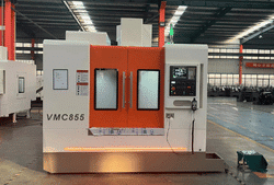
Specifying a machine to match your workholding and part mix? ANTISHICNC builds CNC milling machines and machining centers engineered for rigid, repeatable production.
About This Workholding Guide
This guide synthesizes academic fixture-design research (3-2-1 locating and clamping-force mechanics), peer-reviewed data on zero-point repeatability, and machine-shop trade reporting, cross-checked against shop-floor practice on vises, soft jaws, and fixtures. Where a figure depend on your specific machine, material, and part, we say so rather than imply a precision we can’t guarantee. Reviewed by the ANTISHICNC technical team.
References & Sources
- Fixture Design Criteria (6 Degrees of Freedom)University of Oklahoma, College of Engineering
- Modular Fixturing and the 3-2-1 HeuristicUniversity of California, Berkeley
- A Method for Fixturing and Reorienting a Part for MachiningIowa State University
- Fixtures and Workpiece Clamping Systems in MachiningCIRP Annals (ScienceDirect)
- Zero Point Workholding: Faster Changeovers, Repeatable ResultsModern Machine Shop
- The Principles of Workholding, Part IIIGear Solutions
- US 8,708,323 B2, Quick-Change Mounting SystemUSPTO / Google Patents