


A surface finish chart is the lookup table engineers reach for when they need to turn one roughness value into another, an Ra reading in micrometers into microinches, an RMS figure, an Rz estimate, or an ISO N-grade. This guide hands you the full conversion table, the roughness each machining process tends to leave behind, how to read a finish symbol on a drawing, and how to pick a finish without paying for smoothness the part never needed.
Roughness is the element of surface texture people specify most, yet it travels under at least five different unit systems. A 32 on a US print, an N6 on an old ISO drawing, and 0.8 micrometers on a metric callout all describe the very same surface. That chart below ties them together; the sections after it explain when each value actually matters.
Quick Specs: Surface Finish at a Glance
| Most common parameter | Ra (arithmetic average roughness) |
| Typical machining range | Ra 0.025–25 µm (1–1000 µin) |
| Unit relationship | 1 µm = 39.37 µin | RMS ≈ 1.1 × Ra |
| Current standards | ISO 21920-2:2021 (parameters), ASME B46.1, ASME Y14.36 (symbols) |
| Grinding finish capability | Precision surface & centerless grinding reaches Ra 0.05 µm (2 µin) |
What Is Surface Finish? Ra, Rz and the Parameters That Matter

Surface finish is the texture a manufacturing process leave on a part, and it has three parts: fine, closely spaced roughness; broader waviness (the kind you get from a warped part or tool chatter); and lay, the direction of the dominant tool mark. On a typical shop drawing people use “surface finish” to mean roughness alone, because roughness is what actually gets measured and specified.
Ra, or average roughness, is the value you’ll meet most often, especially on US prints. It’s the arithmetic mean of the absolute deviations of the roughness profile from its mean line. Ra is good at averaging out noise, but it deliberately under-rates the tallest peaks, and that’s exactly what makes it deceptive on a critical sealing, sliding, or high-load surface. That one quirk is why critical drawings add a second parameter.
That second parameter is usually Rz, the mean roughness depth, and it’s built from peaks and valleys rather than an average. Rz takes the five largest peak-to-valley heights inside the sampling length, averages those five, and so almost always lands higher than Ra. It tells you what the worst feature look like, so when a surface has to seal tightly or survive cyclic load, you tighten the Rz callout instead of forcing Ra ever lower. The U.S. leans on Ra; much of Europe and Asia prefer Rz.
A few more parameters round out the picture. RMS (Rq) is the root-mean-square of the same profile and runs about 11% higher than Ra. Rt is the full height from the highest peak to the lowest valley over the whole trace. Rp and Rv isolate the highest peak and lowest valley. NIST calibrates against this full set, Ra, Rq, Rz, Rt, Rp, Rv and the spacing parameter RSm, with a traceable stylus, as described in NIST’s surface-metrology program.
Ra averages and forgives sharp peaks; Rz reports the worst peak-to-valley height. If a surface seals, slides, or carries fatigue load, control both — two parts with the same Ra can behave very differently when one hides a spike the other does not.
The Master Surface Finish Chart (Ra ↔ Rz ↔ RMS ↔ Microinch ↔ N-Grade)

This is what most people come for. This table pulls together the five systems you actually run into: Ra in micrometers, Ra in microinches, RMS in microinches, an Rz estimate, Rt, and the ISO roughness grade (N1–N12). These values follow the preferred-number series used in ASME B46.1 and the ISO grade scale, and they are cross-checked against two independent published charts.
| Ra (µm) | Ra (µin) | RMS (µin) | Rz (µm, approx.) | Rt (µm) | ISO N-Grade | Cutoff λc (mm) |
|---|---|---|---|---|---|---|
| 0.025 | 1 | 1.1 | 0.18 | 0.3 | N1 | 0.08 |
| 0.05 | 2 | 2.2 | 0.4 | 0.5 | N2 | 0.25 |
| 0.1 | 4 | 4.4 | 0.7 | 0.8 | N3 | 0.25 |
| 0.2 | 8 | 8.8 | 1.4 | 1.2 | N4 | 0.25 |
| 0.4 | 16 | 17.6 | 2.9 | 2.0 | N5 | 0.25 |
| 0.8 | 32 | 35.6 | 5.8 | 4.0 | N6 | 0.8 |
| 1.6 | 63 | 69.3 | 11.5 | 8.0 | N7 | 0.8 |
| 3.2 | 125 | 137.5 | 23 | 13 | N8 | 2.5 |
| 6.3 | 250 | 275 | 45 | 25 | N9 | 2.5 |
| 12.5 | 500 | 550 | 90 | 50 | N10 | 2.5 |
| 25 | 1000 | 1100 | 180 | 100 | N11 | 8.0 |
| 50 | 2000 | 2200 | 360 | 200 | N12 | 8.0 |
Ra columns, RMS, Rt, cutoff and N-grade values are all fixed by standard, so you can read straight across. The math is simple and all keyed to Ra: the microinch Ra equals Ra in micrometers times 40, RMS equals Ra times 1.1, and Rt equals Ra times 8.7. The catch sit in the Rz column, where the gray areas show up at the low and high ends of the scale.
The popular Rz ≈ 7.2 × Ra rule is a rough approximation only. For a given Ra, the real Rz can swing from about 4× to as much as 20× higher, because Rz depends on the shape of the profile and the way the material was removed — not on a simple average. Never write an Rz specification by converting from Ra on a critical print. If a drawing needs Rz control, measure Rz directly.
That cutoff length (λc) in the last column is a filter, not decoration. Set it too long and waviness leaks into your roughness reading; set it too short and you under-sample the texture. Match λc to the Ra band shown (see ASME B46.1 / ISO 21920) and your readings stay comparable between instruments and shops.
What Do 32, 63 and 125 Surface Finish Callouts Mean?

US prints still carry bare microinch numbers inside a finish symbol, most often 32, 63, and 125. Each is an Ra ceiling in microinches, and each maps to a metric Ra, an ISO grade, and a realistic way of producing it. Here is what they mean on the floor.
What does a 125 surface finish mean?
A 125 callout means Ra no greater than 125 µin, which is 3.2 µm, or ISO grade N8. That is the default “as-machined” finish, what you get straight off a mill or lathe at normal feeds and speeds, with tool marks you can see and feel. It is the cheapest finish because nothing else is done to it. Specify 125 on non-critical faces, jigs and fixtures, brackets, and anything you plan to paint or coat later. It is the value that says “do not spend extra here.”
What does a 63 surface finish mean?
63 means Ra no greater than 63 µin (1.6 µm, N7), and it’s a solid general machine finish: tool marks are faint, the surface look clean, and most CNC shops hold it with a controlled finishing pass rather than a separate grinding step. Use 63 on mating faces that don’t seal, light-duty bearing seats with a press fit, and visible surfaces where appearance matters but a mirror doesn’t. It costs a little more than 125 because it needs a more careful final cut, but it doesn’t yet demand grinding.
What does a 32 surface finish mean?
At 32, Ra must stay at or under 32 µin (0.8 µm, N6), and this is where finishing operations usually begin: a 32 surface typically needs grinding or a very fine finishing pass, and turning alone rarely reaches it reliably. Specify 32 on sliding surfaces and dynamic seal faces, where lower friction or better wear life earns the extra cost. Below 32, at 16 µin (0.4 µm, N5) and finer, you’re into grinding, honing and lapping, and the price climbs fast.
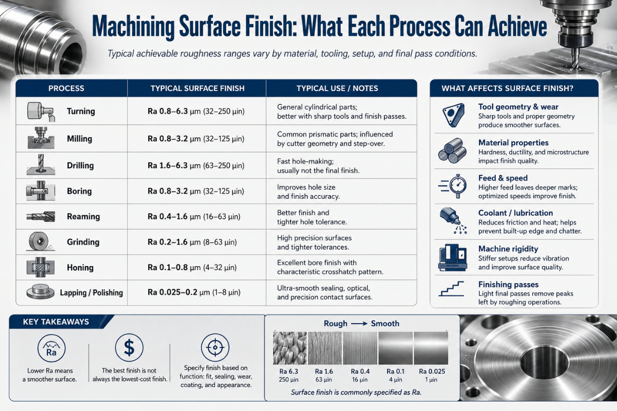
Surface Roughness by Machining Process (Turning, Milling, Grinding, EDM, Lapping)

No single process hits every finish band economically. Push a process past its range and cost jumps or quality gets unreliable, so the right move is usually to add a finishing operation rather than lean harder on the primary cut. The table below show the Ra range each common process tends to produce, handy for matching a target finish to a feasible route before you cut any metal.
| Process | Typical Ra (µm) | Typical Ra (µin) |
|---|---|---|
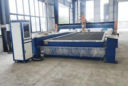
| Flame / plasma cutting | 12.5–25 | 500–1000 |
| Sand casting | 6.3–50 | 250–2000 |
| Drilling | 1.6–6.3 | 63–250 |
| Milling | 0.8–6.3 | 32–250 |
| Turning / boring | 0.4–6.3 | 16–250 |
| Reaming / broaching | 0.8–3.2 | 32–125 |
| EDM (sinker / wire) | 0.2–6.3 | 8–250 |
| Grinding | 0.1–1.6 | 4–63 |
| Honing | 0.05–0.4 | 2–16 |
| Lapping / polishing / superfinish | 0.012–0.2 | 0.5–8 |
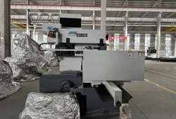
Read the table as a routing tool. If your drawing asks for Ra 0.4 µm (16 µin) on a hardened shaft, turning won’t get you there, you grind it. If it asks for Ra 0.1 µm on a bore, you hone. A grinding step takes a hardened, turned surface from 0.8–1.6 µm down to 0.1–0.4 µm, which is exactly where a precision surface grinder earns its spot in the plan. For round work, a centerless grinding machine holds fine Ra and tight roundness in volume, while cylindrical grinding handles shouldered shafts and bores.
“The mistake we see most often is a ground finish called out on a feature that was never going to leave the lathe. Decide the finishing route when you set the Ra value, not after the part is cut, a 0.2 micrometer callout quietly commits you to a grinding operation and all the fixturing that comes with it.”
- Reaches Ra 0.05–0.4 µm on hardened steel
- Holds size and form together in one operation
- Works on materials too hard to turn or mill cleanly
- Lower material-removal rate than milling or turning
- Adds a setup and a wheel-dressing routine
- Heat and burn risk if coolant or wheel choice is wrong
How to Read Surface Finish Symbols on a Drawing (ISO & ASME)

Every surface finish symbol starts as a check mark with its point resting on the surface being controlled. Three variants tell the shop whether the surface may be machined, and a set of positions around the symbol carry the actual values. Get the variant wrong and you can machine a surface that was meant to stay as-cast or as-forged.
- Basic check markany production method is allowed.
- Check mark with a horizontal barmaterial removal is required (the surface must be machined).
- Check mark with a circlematerial removal is prohibited (leave it as cast, forged, or formed).
Numbers and letters fill fixed positions defined by ASME Y14.36: position a holds the Ra value; b names the production method, coating, or note; c gives the sampling (cutoff) length; d shows the lay direction; e sets the machining allowance; and f carries a second parameter such as Rz 0.4. So a callout reading 32 with “Rz 160” beneath it means Ra no greater than 32 µin and Rz no greater than 160 µin on the same surface.
Lay symbols describe the direction of the tool pattern, and they matter whenever a surface seals or slides against another: = parallel, ⊥ perpendicular, X crossed, M multidirectional, C circular, R radial, and P particulate or non-directional. A seal riding across a parallel lay leaks far more readily than one running along it, which is why the lay callout isn’t optional on dynamic seal faces.
A bare number with no modifier is ambiguous. Without a parameter letter the reader has to assume Ra, and without a max/min mark has to assume a ceiling — but assumptions are not specifications. State the parameter, the value, the cutoff, and the lay wherever function depends on it.
How Surface Roughness Is Measured (Profilometer, Gauge, Comparator)

A finish callout is only as good as the way it get checked. There are three practical levels of measurement, and matching the method to the requirement keep you from under-checking a critical surface or wasting lab time on a bracket.
Your reference method is the contact stylus profilometer: a diamond stylus drags across the surface and its vertical motion is turned into Ra, Rz and the rest. It’s the most accurate route and the one NIST uses for traceable calibration, but it’s slow and the stylus can mark very soft surfaces. Non-contact optical instruments, laser triangulation, confocal microscopy, and white-light interferometry, read the surface with light instead of a tip, so they’re fast, do no damage, and can map a whole area rather than a single line. They show up more and more on functional surfaces where the entire texture matter, not just one trace.
On the shop floor, a surface roughness comparator plate lets an operator judge a finish by touch and eye against known samples. It’s cheap and fast, but it resolves to about one grade at best, fine for a feel check, not for signing off an inspection report. Picture a machinist setting a freshly turned shaft next to a comparator, calling it “about a 63,” while a profilometer reads Ra 1.9 µm: both are “right,” but only one is a number you can record.
Set the cutoff length (λc) before you measure and keep it consistent. The same surface read at λc 0.25 mm and at 0.8 mm gives different Ra numbers, because the filter passes different waviness. Two shops “disagreeing” on a finish are usually just running different cutoffs, line up the λc to the chart band and the argument disappears.
How to Choose the Right Surface Finish (Cost vs Function)

Smoother isn’t better, smoother is more expensive. Each step down in roughness usually adds a process: a finishing pass, then grinding, then honing or lapping. The discipline is to specify the roughest finish that still does the job. Over-specifying “to be safe” is the most common way a drawing quietly inflates part cost.
As a planning heuristic, cost climbs sharply each time you halve Ra below about 0.8 µm (32 µin). Going from 3.2 to 1.6 µm often costs little — it is one more pass. Going from 0.8 to 0.4 µm, then to 0.2 µm, each tends to add a whole operation (grinding, then honing or lapping) plus inspection. Spend your roughness budget where function needs it, and leave everything else at the as-machined band.
Use the map below to match a finish to its job before you commit a number to the drawing.
| Ra band | Typical application | Relative cost |
|---|---|---|
| 6.3–12.5 µm (250–500 µin) | Non-contact, hidden, or rough cast faces | Lowest |
| 3.2 µm (125 µin) | Standard as-machined, painted or coated parts | Low |
| 1.6 µm (63 µin) | Mating faces, light press fits, visible surfaces | Moderate |
| 0.8 µm (32 µin) | Sliding surfaces, static seals (needs finishing) | High |
| 0.4 µm (16 µin) | Dynamic seals, bearing seats (ground) | Higher |
| ≤ 0.2 µm (8 µin) | Precision bearings, hydraulics, optical (honed/lapped) | Highest |
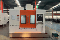
The same logic drive equipment choice. Roughest bands come straight off a metal turning lathe or a milling machine; the fine bands move to dedicated metal grinding equipment. Mapping the route up front avoids the worst case, finding out after the cut that the finish on the print was never achievable on the machine that made the part.
Industry Outlook: ISO 21920:2021 and In-Process Measurement

If you learned surface texture from ISO 4287 and ISO 1302, your reference is out of date. In December 2021 the ISO 21920 series, Parts 1, 2 and 3, was published and consolidated the older profile standards. ISO confirms that ISO 21920-2:2021 now carries the terms, definitions and parameters, while ISO 4287:1997 is formally withdrawn. The standard entered its five-year review in October 2025, so another revision is already on the way.
In practice, that effect lands on your drawings. Many charts still in circulation, including several that rank at the top of search, keep citing ISO 4287, ISO 4288 and ISO 1302. Those parameter values have not changed, but the governing reference has. If you are issuing new prints in 2026, point the callout at ISO 21920 (or ASME B46.1 for US work) and check that no inherited title-block note is naming a withdrawn standard.
A second shift is happening in measurement. Profile Ra is still the workhorse, but areal parameters, Sa, Sz and the rest of the ISO 25178 family captured by optical instruments, are moving from the metrology lab toward the line. NIST’s surface-topography work points the same way: characterizing a whole area, not a single trace, where function depends on the full texture. For most shops Ra still rules, but if you are specifying critical sealing, sliding or optical surfaces, it is worth asking whether an areal parameter describes the requirement better than a single profile number.
Frequently Asked Questions
Q: What are the categories of surface finish?
View Answer
Q: Is a lower Ra number always better?
View Answer
Q: What is the difference between Ra and RMS?
View Answer
Q: What surface finish can a grinder achieve?
View Answer
Q: Does surface finish affect part performance?
View Answer
ANTISHICNC builds surface, cylindrical and centerless grinding machines that hold fine finishes and tight tolerances in production. Tell us your target Ra and material, and we’ll spec the right machine.
Why We Publish This Chart
ANTISHICNC builds surface, cylindrical and centerless grinding machines, so the fine end of this surface finish chart, the Ra 0.05–0.4 µm band where grinding takes over from turning and milling, is where our equipment works every day. We put this reference together to settle the conversions our customers ask about most, and to flag where a “simple” Ra-to-Rz conversion can mislead a critical print.
References & Sources
- ISO 21920-2:2021, Surface texture: Profile, terms, definitions and parametersInternational Organization for Standardization
- ASME B46.1 Surface TextureAmerican Society of Mechanical Engineers
- ASME Y14.36 Surface Texture SymbolsAmerican Society of Mechanical Engineers
- Stylus ProfilometerU.S. National Institute of Standards and Technology
- Surface Texture and TopographyU.S. National Institute of Standards and Technology