


Machining surface finish is the texture a cutting process leave on a part, the fine pattern of peaks and valleys you can feel with a fingernail but usually need an instrument to measure. It decides how a sealing face holds pressure, how a shaft survives a rotating seal, and how much a part cost to make. Two parts can hit the same dimension on the print and still behave nothing alike because one was turned at Ra 3.2 µm and the other ground to Ra 0.4 µm. This guide is about the cause-and-control side: which process holds which finish, the five inputs you actually change at the machine, the simple formula that predicts a turned finish before you cut, and how to read a fault back to its root.
Quick Specs: Machining Surface Finish
| What it measures | Micro-irregularities left by machining — roughness, plus waviness and lay |
| Most-used parameter | Ra (arithmetic average roughness), in µm or µin |
| Standard “as-machined” finish | Ra 3.2 µm = 125 µin |
| Turning / milling range | Ra 0.8–6.3 µm (32–250 µin) |
| Grinding / honing / lapping | Ra 0.1–0.8 µm down to under 0.05 µm |
| Governing standards | ISO 21920 (2021), ISO 1302, ASME B46.1, ASME Y14.36 |
| Biggest single lever (turning) | Feed per rev vs tool nose radius |
What “Machining Surface Finish” Actually Means

Surface finish is the broad description of a machined surface’s texture, and it breaks into three separate components — roughness, waviness, and lay. Mixing them up is the most common reason a drawing callout and a finished part disagree. In day-to-day machining the word usually means roughness, reported as an Ra value in micrometres: the fine peaks and valleys the cutting edge leaves behind on the surface.
- ✔Roughnessthe finely spaced surface irregularities, the peaks and valleys left directly by the cutting edge. This is what machinists usually mean when they say “surface finish,” and it’s what Ra reports.
- ✔Wavinesscoarser, longer-wavelength deviations from vibration, deflection, or a warped setup. A part can be a smooth surface (low roughness) yet wavy.
- ✔Laythe direction of the predominant surface pattern, set by the type of machining (circular on a turned face, linear on a ground or milled flat).
“Surface texture” is the umbrella term for all three; “surface roughness” is the roughness component on its own. The ASME B46.1 standard defines Ra formally as the arithmetic average of the absolute height deviations of the measured profile from its mean line, taken over a sampling length. In plain terms: average how far the surface strays from a centre plane, up and down, and you get Ra.
These three elements together make up the texture of a surface, and every type of surface finish is just a different mix of them. Engineers describe this surface geometry with roughness parameters, Ra, Rz and Rt, each a different way to reduce a complex profile to a single number. Common surface finishes on a machined part range from coarse to mirror-bright, but they all describe the same metal surface finish: how far the real surface departs from a perfect plane, including both the waviness and the spaced surface irregularities, the small irregularities in the surface and the irregularities on a surface left by chips.
Reading the Numbers: Ra, Rz and Common Callouts

Ra dominates prints because it’s stable and easy to measure, but it averages away the extremes. Rz captures the average of the largest peak-to-valley heights across several sampling lengths and is more sensitive to a single deep scratch, useful for sealing and fatigue-critical surfaces. Rmax (or Rt) is the single biggest peak-to-valley distance in the evaluation. Surfaces can pass on Ra and still fail on Rz when they carry occasional deep tool marks.
Ra is the roughness average, formally the arithmetic average of surface heights’ deviations from the mean line, which is why it’s also called the average surface roughness. Because it sums many small surface height deviations into one figure, two surfaces with very different roughness profiles can share the same Ra. Any single roughness profile reading therefore tells you less than the full roughness parameter set, so critical drawings pair Ra with Rz or a tighter parameter. Standard surface roughness values cluster on a fixed scale, and most callouts pick one of these roughness levels rather than an arbitrary number.
What is Ra 3.2 surface finish?
Ra 3.2 µm (equal to 125 µin) is the standard “as-machined” finish, the texture a competent turning or milling pass produces without any extra finishing work. It carries faintly visible tool marks, feels smooth to the touch, and is the default for general machined surfaces, mounting faces, and non-sealing features. Specifying anything finer than Ra 3.2 means committing to extra passes, special tooling, or a secondary process, so Ra 3.2 is the cost-neutral baseline unless function demands better.
| Ra (µm) | Ra (µin) | ISO N-grade | Feel / typical use |
|---|---|---|---|
| 6.3 | 250 | N9 | Visible marks; rough machining, non-critical |
| 3.2 | 125 | N8 | Standard as-machined; general surfaces |
| 1.6 | 63 | N7 | Fine finish pass; light sliding fits |
| 0.8 | 32 | N6 | Bearing seats, sealing faces (needs care or grinding) |
| 0.4 | 16 | N5 | Ground surfaces; dynamic seal journals |
| 0.2 | 8 | N4 | Precision grinding / honing |
Conversion convention: 1 µm ≈ 40 µin. This surface roughness conversion lets you read any surface roughness chart in either unit. For a full Ra surface finish chart with RMS, CLA and Rt columns, plus a surface roughness comparison chart, see our guide to measuring surface roughness.
Surface Finish Symbols on an Engineering Drawing

A finish requirement reach the shop as a symbol, not a sentence. Its base symbol is a check mark sitting on the surface it control. Three variants change the meaning:
- ✔Plain check mark, surface texture requirement, any process allowed.
- ✔Check mark with a horizontal bar, material removal (machining) is required.
- ✔Check mark with a circle, material removal is prohibited (leave the as-cast/as-formed surface).
These surface roughness symbols (also written as surface texture symbols) pack the surface finish parameters, value, cutoff and lay, into one mark. Ra values sit at the upper-left of the symbol; a sampling (cutoff) length and a lay-direction symbol can be added below and to the right. Lay symbols tell you which way the pattern should run: = parallel, ⊥ perpendicular, X crossed, M multidirectional, C circular, R radial. Lay matters for seals and sliding parts, where the scratch direction relative to motion changes leakage and wear.
ISO and ASME draw the same idea differently. Under ASME Y14.36M the value is shown in µin; under ISO 1302 / ISO 21920 it is shown in µm with the parameter letter (for example “Ra 0.8”). If a callout shows a bare number with no parameter, confirm whether it is Ra or Rz and which units, a “32” in µin (Ra 0.8 µm) is a very different part from “32” read as Rz.
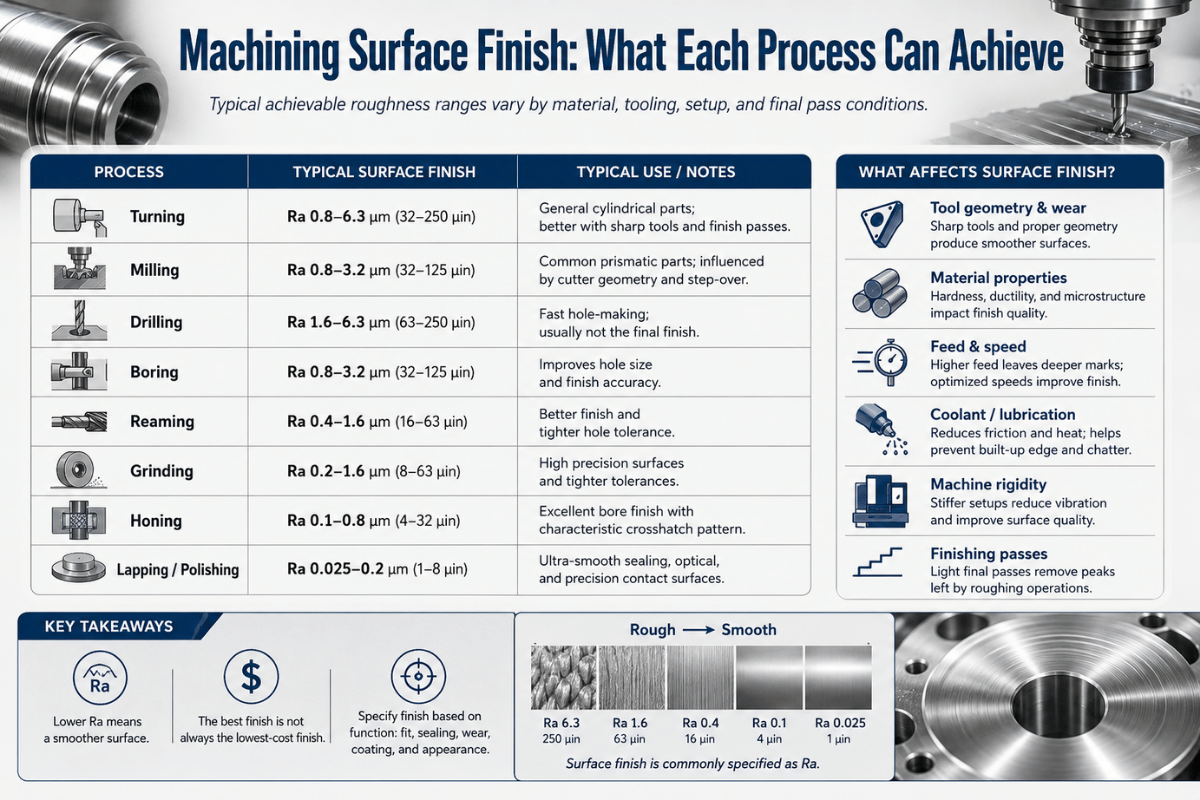
What Finish Each Machining Process Can Hold

One fact matter more than any feeds-and-speeds tweak: the process sets the floor. You can’t tune a roughing pass into a mirror, past a point, the only way to a finer Ra is a different operation. As a builder of turning, milling, grinding and EDM machines, we set the process bracket first, then optimise inside it. The table below is the Process-to-Ra Window — a realistic, dual-unit map of what each operation hold in production, not a lab best case.
| Process | Ra (µm) | Ra (µin) | Typical role |
|---|---|---|---|
| Rough turning / milling | 3.2–12.5 | 125–500 | Stock removal, non-critical |
| Finish turning / milling | 0.8–3.2 | 32–125 | Standard machined surfaces |
| Drilling | 1.6–6.3 | 63–250 | Holes before reaming |
| Reaming / boring | 0.8–3.2 | 32–125 | Sized, round holes |
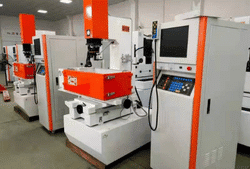
| EDM (wire / sinker) | 0.4–6.3 | 16–250 | Hard or complex shapes |
| Surface / cylindrical grinding | 0.1–0.8 | 4–32 | Bearing seats, seal journals |
| Honing | 0.05–0.4 | 2–16 | Bores, hydraulic cylinders |
| Lapping | <0.012–0.1 | 0.5–4 | Gauges, optical, sealing flats |
Each type of machining leaves its own signature: a turned part shows circular lay, a milled part show linear marks, and electrical discharge machining (EDM) leaves a uniform matte. These machined surface finishes are the product of the cutting or eroding mechanism plus the machining steps that precede the final pass, rough, semi-finish, then finish. A CNC machined surface from a finishing pass is far smoother than the same CNC machining surface left after roughing. Read the Process-to-Ra Window above as a machining surface finish chart: match the desired surface finish to the process that can reach it, then optimise inside that window.
Sources: process bands cross-checked against engineering handbooks and standards practice. Grinding can reach Ra 3–6 µin in production, which is why anything below about Ra 0.8 µm usually moves to grinding equipment rather than being chased on a lathe or mill.
“Most ‘bad finish’ tickets we see aren’t a feeds-and-speeds problem at all, the part was asked to hold a grinding-class number on a turning operation. Pick the process for the Ra first; the parameters only fine-tune inside that window.”
ANTISHICNC turning & grinding engineering team
The 5 Levers That Control Surface Finish

Once you’re in the right process window, five inputs decide the actual Ra. We call this the 5-Lever Finish Control Modelpull them in order, because the first two do most of the work on a turned or milled surface.
- Feed per revthe dominant geometric driver. Lower feed, finer finish (with a limit, see the next section).
- Tool nose radiusa bigger radius spreads the feed marks and lowers theoretical roughness, but raises cutting force.
- Cutting speedmust be high enough to get out of the built-up-edge zone (see troubleshooting).
- Edge / tool conditiona sharp, correctly coated, unworn edge; a wiper insert if you want feed and finish.
- Rigidity & coolanta stiff setup and clean lubrication kill the waviness and tearing the first three levers can’t.
Lever 1 and 2 are linked by simple geometry, and you can predict a turned finish before the spindle ever turn.
Theoretical peak-to-valley roughness in turning is Rt ≈ f² ÷ (8 × r), where f is feed per rev and r is the tool nose radius. Worked example: f = 0.2 mm/rev, r = 0.8 mm → Rt ≈ (0.2 × 0.2) ÷ (8 × 0.8) = 0.04 ÷ 6.4 = 0.00625 mm = 6.25 µm. Now halve the feed to 0.1 mm/rev: Rt ≈ 0.01 ÷ 6.4 = 1.56 µm, roughly a quarter of the height, because feed is squared. Plug in your own f and r before you cut: it tells you whether the finish is even reachable by turning, or whether the part need grinding.
That same geometry explains the wiper insert. A wiper grind a small flat just past the nose radius, so the marks left at a higher feed are wiped smooth, letting you double the feed and keep the finish. That trade-off is real and documented: turning inserts with a larger effective radius “produce the best surface quality” but “increase cutting force,” per Google Patents EP1631410A1, so they need a rigid setup. For where speeds and feeds fit the bigger picture, see our feeds and speeds guide.
How to Improve Surface Finish: A Working Sequence

Surface finish is not improved by luck or by simply slowing the machine down. It responds to a defined set of levers — edge condition, feed and nose radius, finishing strategy, cutting speed, and rigidity — and the order you adjust them in decides how fast you reach the number. The sequence below is the one we hand operators when a part comes back rough, ranked by effect rather than by habit.
How to get better surface finish in machining?
Work the levers in order of effect rather than changing everything at once. Fastest gains on a turned or milled part come from the cutting edge and the feed-to-nose-radius relationship, then the finishing pass, then speed and coolant. Below is the sequence we hand to operators chasing a number.
- Confirm the edge is sharp and unworn, and set on or just below centre height. An insert above centre rubs instead of cuts.
- Leave at least one nose radius of stock for a dedicated finishing pass, never less.
- Lower the feed or fit a larger nose radius / wiper insert (use the feed-squared rule to size the move).
- Take a spring (zero-depth) pass to remove deflection-driven leftover.
- Raise cutting speed to get clear of the built-up-edge band; add or improve coolant.
- If the target is below ~Ra 0.8 µm, stop tuning and move to grinding or honing.
The goal is a smooth surface that meets the desired surface finish without wasted passes; chasing a finer level of roughness than the part need only adds cost. Controlled university milling experiments confirm surface roughness tracks feed directly (Clemson University study on 6061 aluminum), so feed is the lever to size first. One counter-intuitive caution: starving the feed doesn’t always help. Practitioners report that dropping below a real finishing feed (roughly 0.15 mm/rev) can make a finish worse, because the edge start to rub and smear rather than shear cleanly.
Why Finish Goes Wrong: 6 Common Causes and Fixes

Most finish faults announce their cause if you read the surface instead of guessing. A torn edge, a regular wave, a bright dragged smear — each pattern points back to one dominant variable. Use the 6-Symptom Finish Fault Decoder below: match what you see on the part to a symptom, find the usual cause, then change that single variable before touching anything else.
| Symptom on the part | Likely cause | Fix |
|---|---|---|
| Regular wavy / drumming marks | Chatter — vibration, often from interrupted or unstable cutting | Stiffen setup, shorten overhang, change speed/depth to dodge the resonance |
| Torn, ragged, dull surface | Built-up edge at low/mid speed on gummy material | Raise speed out of the BUE band, sharper/coated edge, better coolant |
| Bright smeared drag, no clean cut | Tool above centre height — it rubs, not cuts | Reset edge to centre or slightly below |
| Coarse periodic ridges | Feed too high for the nose radius | Lower feed or increase nose radius (feed-squared rule) |
| Random scratches / scoring | Recutting chips, swarf dragged across the surface | Improve chip evacuation, coolant flush, chipbreaker geometry |
| Finish getting worse over a run | Progressive tool wear | Index/replace edge on a tool-life schedule, not on failure |
A widely held belief is that lower cutting speed always gives a finer finish. Controlled studies say otherwise: at low cutting speed a built-up edge form and roughens the surface, and Ra falls as speed rises out of that band. University research on turning confirms the relationship is “positive due to the formation of built-up edge” at low speed (SUST study on cutting parameters; corroborated for AA7075 in ScienceDirect). If a finish is torn and you reach for the speed override to slow down, you may be making it worse.
Matching Finish to Function: How Tight Is Tight Enough?

On many drawings, the most expensive line is an over-tight finish callout. Tighter Ra isn’t free: going from Ra 3.2 to Ra 0.8 µm is commonly cited as adding roughly 2–4× to machining cost because it forces extra finishing passes, special tooling, and stricter inspection. Specify the finish the function need, no finer, using the parameter and symbol rules in ISO 21920 so the callout means the same thing to every shop.
| Part role | Sensible max Ra | Why |
|---|---|---|
| General / non-contact surface | Ra 3.2–6.3 µm | As-machined is fine; tighter wastes money |
| Static seal / gasket face | Ra 1.6–3.2 µm | Gasket conforms; lay matters more than ultra-low Ra |
| Press / sliding fit | Ra 0.8–1.6 µm | Controls friction and retained interference |
| Dynamic seal journal / bearing seat | Ra 0.2–0.8 µm | Seal life; usually ground |
| Optical / gauge / lapped flat | Ra <0.1 µm | Function demands it; lapping/honing only |
Different part roles need different surface roughness, and different levels of surface roughness carry very different costs. Sometimes a rougher finish is the right call: a matte or satin finish (a deliberate satin finish, not a polished one) may be specified for appearance or to hide handling marks rather than for function. These finish variations are exactly why one component carries several callouts instead of one blanket grade.
A practical rule: if you can’t name the function that need it, don’t specify below Ra 1.6 µm. Specify the right surface finish for each feature, treat the tightest callout as the final surface finish to schedule last, and remember that precision machining time, not material, is what an over-tight number buy. Match-finish-to-function decisions are cheaper to make on the drawing than to argue over at first-article inspection.
Verifying the Finish You Specified

Two checks cover most shops. A surface comparator (a set of reference coupons machined to known Ra grades) lets an operator judge a finish by sight and fingernail in seconds, fine for go/no-go on the floor. A stylus profilometer drags a fine tip across the surface and reports a traceable Ra/Rz against a defined cutoff length, which is what you need for inspection records and tight callouts. Roughness measurement turns the surface into a number: the instrument take the measurement of surface roughness from a measured surface, tracing the surface profile so the surface roughness measurement is repeatable. Match the part surface and its roughness specifications to the right instrument, and pick the cutoff to match the feature, because the wrong cutoff can report a passing part as failing. For the full method, instruments, and Ra-versus-Rz detail, see our dedicated guide on how to measure surface roughness.
Where Machining Surface-Finish Requirements Are Heading

Two shifts are worth acting on now. First, the governing standard is changing: ISO 21920-2:2021 supersedes ISO 4287/4288, the long-standing profile-parameter standards, and Part 1 absorbs ISO 1302’s symbology (Surface Metrology Guide). Its practical consequence for buyers: a “Ra 0.8” on a 2026 drawing and a 2015 drawing may reference different definitions of sampling and evaluation, confirm which standard a callout is built on before you quote or inspect it.
Second, the process economics under the finish are moving. Hard turning is increasingly used as an alternative to grinding for hardened (>45 HRC) parts to reach Ra 0.2–0.4 µm, because it makes recyclable chips instead of grinding sludge and can cut cycle time (Production Machining). That doesn’t retire grinding, grinding, honing and lapping still own everything below roughly Ra 0.1 µm, but it changes which machine earns the work for the mid-fine band. If you’re specifying or buying capability for sub-micron finishes, the decision is no longer automatically “grind it.” Match the process to the Ra and the hardness, and revisit it as hard-turning tooling improves.
Frequently Asked Questions
Q: What is the standard surface finish in machining?
View Answer
Q: What’s the difference between surface roughness and surface finish?
View Answer
Q: Does anodizing or electroplating change my machined surface roughness?
View Answer
Q: Why doesn’t specifying Ra 1.6 or Ra 0.8 always cost more?
View Answer
Q: Which machining process gives the smoothest finish?
View Answer
Q: Can you combine several surface finishes on one part?
View Answer
Yes, and it is normal practice. A single component often carries several callouts: a ground Ra 0.4 µm bearing journal, Ra 1.6 µm sealing faces, and as-machined Ra 3.2 µm everywhere else. Each feature gets the finish its function needs, which keeps cost down versus finishing the whole part to the tightest number. One sequencing rule matters: tighter surfaces are usually finished last, so heat and clamping from later operations do not spoil a surface already brought to size.
Call out each surface’s symbol, value, and lay separately, and flag any “finish after heat treat” or “finish after plating” note, so the shop plans operation order and doesn’t grind a journal a later process would only distort again.
References & Sources
- Effect of Machining Feed on Surface Roughness in Cutting 6061 AluminumClemson University
- Impact of Toolpath Pitch Distance on Cutting Tool Nose Radius and Surface FinishNIH PMC
- Study the Effect of Cutting Parameters (Speed, Feed, Depth) on Surface RoughnessSudan University of Science & Technology
- ISO 21920-2:2021, Geometrical product specifications, Surface texture: ProfileISO
- ASME B46.1 / Y14.36, Surface Texture & Surface Texture SymbolsASME
- EP1631410A1, Cutting tool having a wiper nose cornerGoogle Patents
About This Analysis
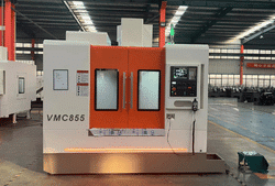
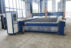
This machining surface finish guide reflects the process-first view of a machine-tool builder: ANTISHICNC manufactures the turning lathes, milling machines, surface grinders, tool & cutter grinders and EDM equipment that hold the finish bands in the Process-to-Ra Window above. The capability ranges and the feed-squared example are drawn from standards practice and machining references, then framed by how those processes behave on real equipment. Reviewed by the ANTISHICNC technical team.
Related Articles
- How to Measure Surface Roughness, Ra, Rz, instruments and cutoff length
- Feeds and Speeds, setting cutting parameters that protect finish and tool life
- Machining Stainless Steel, taming work hardening and built-up edge
- Machining Aluminum, finish, BUE and nose-radius strategy
- Machining Brass, free-cutting behavior and surface quality