






Magnetic workholding fixtures make ferromagnetic workpieces by routing a closed magnetic flux circuit between alternating North and South poles through the part and creating perpendicular clamping force via Maxwell attraction. Mechanical vises and edge clamps cause localized elastic bending and don’t pull the entire contact face uniformly. This is especially problematic for precision metalworking because localized bending can cause parts to bind. Unlike mechanical vises or edge clamps that cause localized elastic bending, magnetic chucks pull the entire contact face uniformly, enabling 5-sided milling clearance, eliminating jaw distortion on thin plates, and reducing part setup times by up to 70% in precision metalworking shops.
1. How Magnetic Workholding Works: Closed Flux Circuits and Maxwell’s Pull Force
Every magnetic workholding and magnetic work holding fixture designed for light toolroom surface grinding or heavy 5 axis CNC milling operates on the same fundamental principle of an electromagnetic field. A continuous closed magnetic circuit is a must. When a machinist places a carbon steel plate on a magnetic chuck or mag chuck top plate, the workpiece acts as an attracted mass. In truth, the workpiece provides the magnetic bridge between the North and South poles embedded on the chuck body.
The magnetic circuit starts in the chuck, where dense lines of magnetic force are created by permanent magnet blocks and magnetic blocks (such as Neodymium-Iron-Boron or Alnico alloys) or electric copper coil windings. These flux lines pass vertically through high-permeability steel pole pieces and cross the physical boundary into the workpiece. They cross horizontally through the steel and re-enter the pole piece on the opposite side of the steel housing. If a workpiece spans both poles, it completes a closed magnetic path with low reluctance. If a workpiece is in contact with only one pole, magnetic flux can’t return efficiently, resulting in high flux leakage into the surrounding area and a drastic reduction of holding force to near zero.
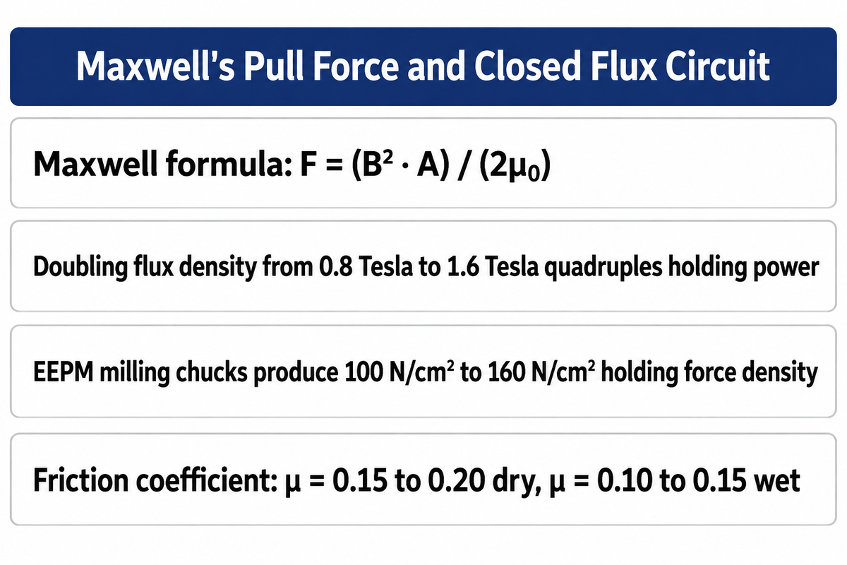
The magnetic pull force holding the workpiece down against the chuck is described by Maxwell’s pull equation for magnetic circuits:
Maxwell’s Pull Force Equation:
F = (B² · A) / (2μ₀)
- F:Normal magnetic clamping force in Newtons (N).
- B: Magnetic flux density in Tesla (T) at the contact interface.
- A: Total effective magnetic pole contact area in square meters (m²).
- μ₀: Magnetic permeability of free space (4π × 10⁻⁷ H/m).
Because magnetic pull force scales with the square of magnetic flux density (B²), small variations in magnetic saturation produce massive changes in clamping performance. For example, doubling flux density from 0.8 Tesla to 1.6 Tesla quadruples holding power. In clean, close-tolerance industrial applications with solid low-carbon steel, modern electro-permanent magnetic (EEPM) milling chucks routinely produce a standardized holding force density between 100 N/cm² and 160 N/cm² (equivalent to 10 to 16 bar, or approximately 145 to 230 psi) across every active square centimeter of pole contact.
However, it’s important for machinists to distinguish between a ‘normal’ pull force and a lateral sliding resistance. Maxwell’s equation determines the holding force along the Z-axis. When an end mill or face mill engages the workpiece, cutting loads produce lateral shear forces (parallel) on the chuck face. Resistance to sliding is attributed to the coefficient of friction between the clean steel of the chuck top plate and the workpiece (which is typically μ = 0.15 to 0.20 dry, and μ = 0.10 to 0.15 with cutting fluid). Therefore, an engineering calculation must be performed to determine the vertical retention and the dynamic shear margins to ensure that the shear is greater than the load before metal is removed.
What is the basic principle of magnetic workholding?
The core operating principle of industrial magnetic workholding and workholding magnets relies strictly on completing a closed magnetic flux circuit between alternating North and South poles through a ferromagnetic workpiece. When ferrous steel bridges adjacent magnetic poles, dense magnetic flux travels vertically out of the North pole, traverses horizontally through the solid core of the workpiece metal, and returns downward into the adjacent South pole, completing an uninterrupted closed loop with minimal magnetic reluctance. This closed circuit generates strong perpendicular downward clamping attraction governed directly by Maxwell’s pull equation. Because clamping force acts uniformly across the entire bottom contact face rather than concentrating high localized mechanical stresses at mechanical vise jaws or perimeter toe clamps, machined components remain exceptionally flat, experience superior vibration damping, and avoid elastic bending distortion entirely during high-speed CNC spindle operations.
2. Comparing Permanent vs Electromagnetic vs Electro-Permanent (EEPM) Chucks
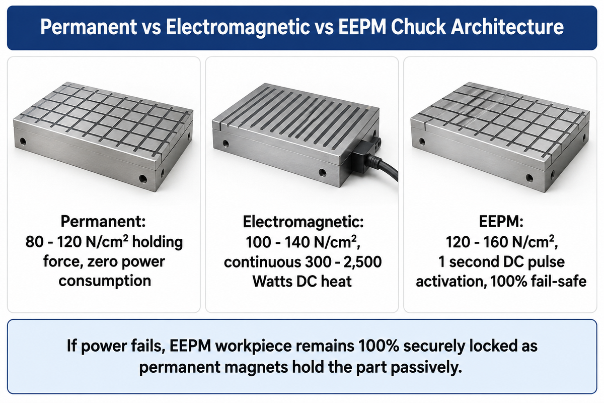
Industrial machine shops select among three distinct magnetic chuck architectures: manual permanent magnetic chucks, electromagnetic chucks, and electro-permanent magnetics (EEPM) chucks. Each system embodies distinct machining trade-offs for holding force density, thermal stability, and power failure safety and automation integration.
Manual Permanent Magnetic Chucks: Liniings and arrays of permanent ceramic or rare earth magnets in these chucks are either stationary or sliding. A manual operating lever alters the internal magnets to align or misalign opposing poles. When aligned, flux passes through the workpiece; when misaligned, flux takes an internal path through the chuck, releasing the part. These permanent chucks don’t require power, produce no heat, and can never fail. However, there are limitations: large chucks require a significant amount of manual effort to activate, and can’t be automated by CNC M-code commands.
Electro-magnetic Chucks: DC current flowing through soft-iron coils embeds electromagnets that either align or misalign flux pathways. An adjustable DC power supply provides fine control for pulling force, which is critical for processes involving thin stock. Reversing polarity can also rapidly demagnetize parts. The constant flow of current through the coils generates heat, causing the top plate to expand by 10°C to 25°C in a shift. This thermal expansion ruins the chuck’s precision flatness and introduces a thermal bow, known as crowning. An unexpected power failure disrupts cooling and causes the workpieces to lose their alignment with the rotary tables, which can only be prevented by an expensive battery backup system.
Electro-Permanent Magnetic (EEPM) Chucks: EEPM technology from builders like Techniks predominates in modern CNC milling and heavy manufacturing. An EEPM chuck uses high-coercivity Neodymium (NdFeB) permanent magnets with reversible-coercivity Alnico permanent magnets, sandwiched by copper coils. To activate the chuck, a 1 second DC pulse is sent to the coil, flipping the magnetic orientation of the Alnico magnets, and bringing their flux in line with the Neodymium magnets and out through the workpiece. Once pulsed, the magnets retain full clamping force passively, without any electric current or heat buildup, forever. A reverse 1 second pulse demagnetizes the Alnico cores to release the part. Hence, EEPM chucks integrate the permanent magnets’ fail-safe and stability with the convenience of push-button systems.
| Operational Parameter | Manual Permanent Chuck | Pure Electromagnetic Chuck | Electro-Permanent (EEPM) Chuck |
|---|---|---|---|
| Clamping Force Density | 80 – 120 N/cm² (115 – 175 psi) | 100 – 140 N/cm² (145 – 200 psi) | 120 – 160 N/cm² (175 – 230 psi) |
| Power Consumption During Machining | 0 Watts (Pure passive) | 300 – 2,500 Watts (Continuous DC) | 0 Watts (1-second pulse only) |
| Thermal Drift & Heat Generation | 0°C rise (No thermal growth) | +10°C to +25°C continuous thermal rise | 0°C rise (Cold operation) |
| Safety During Power Blackout | 100% Fail-Safe (Cannot release) | Hazardous: Releases instantly without UPS | 100% Fail-Safe (Full magnetic lock retained) |
| Switching Time | Manual lever (3 – 10 seconds) | Electronic switch (0.5 – 2 seconds) | M-code electric pulse (0.8 – 1.5 seconds) |
| Variable Clamping Force Control | Coarse partial lever stroke | Stepless progressive voltage dial | Multi-stage programmable pulse levels |
| CNC Automation Compatibility | None (Requires manual operator) | High (Relay / M-code interface) | Full automated pallet / robot integration |
| Aplicaciones primarias | Toolroom surface grinders, EDM tables | Large Blanchard rotary grinders | 5-axis CNC machining centers, heavy milling |
For machine shops running CNC vertical machining centers or automated pallet systems, EEPM workholding is the definitive industry choice. It delivers maximum holding force without thermal crowning while meeting strict international machine tool safety standards such as ISO 16156.
What happens to a magnetic chuck if the power goes out?
If power fails on an electro-permanent magnetic (EEPM) or manual permanent chuck, the workpiece remains 100% securely locked as permanent magnets hold the part passively. Thus, Machining stops safely without losing clamping force. In the case of an electromagnetic chucks, holding is lost immediately upon loss of electrical current. Without an automated uninterruptible power supply (UPS), the workpiece will fly off spinning tables, which poses a dangerous shop condition.
3. Pole Pitch and Geometry: Fine Pole Grinding vs Standard Square Pole Milling
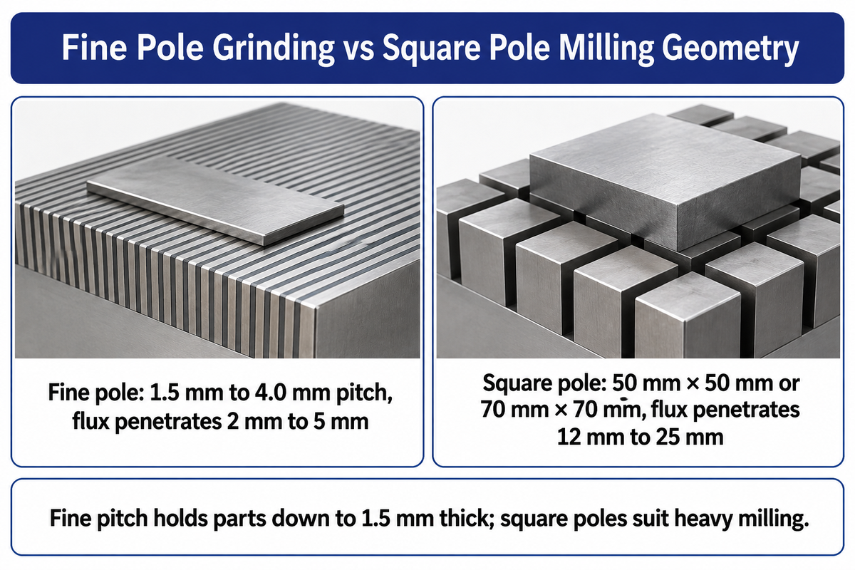
The layout and spacing of magnetic poles on the chuck face (pole pitch) governs the depth of penetration of magnetic flux loops and sets a minimum thickness of workpiece. A frequent user error occurs when steel plates are mounted on coarse milling chucks expecting clamping and instead encounter degraded tool life, workpiece fly-off and magnetized cutting tools.
Fine Pole Chucks (Grinding & Thin Parts): Fine pole configurations alternate steel pole strips with non-magnetic brass or epoxy laminations spaced at 1.5 mm to 4.0 mm intervals (micro-pitch). Because the North and South poles sit extremely close together, magnetic flux loops arch through a shallow path above the table surface, penetrating only 2 mm to 5 mm into the part. Fine pole tables are purpose-built for thin sheet stock, shims, precision gauge blocks, and surface grinding operations. The shallow flux loop concentrates holding power right at the contact interface, ensuring that parts as thin as 1.5 mm achieve sufficient magnetic saturation without letting flux spill through the top surface.
Coarse Square Pole Chucks (CNC Milling & Mold Bases): Milling tables require deep flux penetration to anchor rough, thick billets against aggressive cutting loads. Modern milling chucks feature square checkerboard pole geometries, typically 50 mm × 50 mm or 70 mm × 70 mm. With poles spaced widely apart, magnetic flux arcs deeply into the metal, penetrating 12 mm to 25 mm into the workpiece core. This deep saturation creates high holding force over broad contact zones. However, if a machinist places a 3 mm thick sheet onto a 70 mm square pole chuck, the thin plate saturates almost immediately. The excess flux shoots straight out the top face into the machine enclosure, creating weak clamping, vibrating under the cutter, and strongly magnetizing the rotating end mill, which causes metal chips to pack tightly into the tool flutes.
| Pole Pitch Specification | Physical Pitch Dimensions | Max Flux Penetration Depth | Minimum Part Thickness | Recommended Machine Processes |
|---|---|---|---|---|
| Micro-Fine Pole | 1.5 mm steel + 0.5 mm brass (2.0 mm total) | 2.5 mm – 3.5 mm | 1.0 mm (0.040 in) | Precision toolroom surface grinding, thin shims, EDM |
| Standard Fine Pole | 3.0 mm steel + 1.0 mm brass (4.0 mm total) | 5.0 mm – 7.0 mm | 2.5 mm (0.100 in) | Rotary surface grinding, small stampings, hardened die plates |
| Medium Square Pole | 50 mm × 50 mm pole blocks | 12 mm – 16 mm | 10.0 mm (0.394 in) | General CNC vertical milling, small mold bases, 5-sided profiling |
| Heavy Square Pole | 70 mm × 70 mm pole blocks | 18 mm – 25 mm | 15.0 mm (0.590 in) | Heavy roughing mills, large forging billets, structural steel plates |
| Radial Pole Pattern | Concentric pie wedges radiating outward | 8 mm – 15 mm | 6.0 mm (0.236 in) | Rotary turning tables, bearing ring boring, Blanchard grinding |
When selecting a magnetic chuck, the 1.5x Thickness Saturation Rule is applied: For linear pole assemblies, the workpiece thickness must equal at least 1.5 times the pole pitch. For square assemblies, the thickness meets the minimum threshold. If the thickness doesn’t meet the threshold, magnetic flux isn’t concentrated and retention loss is rapid.
How thick does a workpiece have to be for magnetic holding?
A workpiece should generally be at least 1.5 times thicker than the chuck’s pole pitch to absorb the magnetic circuit without oversaturating. For fine-pole grinding chucks with 1.5 mm to 4.0 mm spacing, parts as thin as 1.5 mm to 3.0 mm clamp securely. For heavy milling chucks with 50 mm or 70 mm square poles, workpieces must be at least 10 mm to 15 mm thick to capture deep flux loops and prevent magnetic spillover through the top face.
4. 5-Sided CNC Milling with Magnetic Tables: Pole Extensions and Self-Shimming Fixtures
The single greatest shop productivity return on investment for magnetic workholding in CNC milling is unobstructed 5-sided tool access. Traditional machine vises and toe clamps block part perimeters, requiring operators to program multiple machine setups, flip workpieces between operations, and perform multiple datum touch-offs. A magnetic chuck grips exclusively from the bottom face leaves the top and bottom faces and all four side faces open to cutters, in a single Fiiganuts clamping cycle.
But clamping raw flame-cut plates, hot-rolled steel or unmachined castings billets, directly onto a bare magnetic table poses two serious technical risks: Through-hole tool clearance and elastic workpiece distortion.
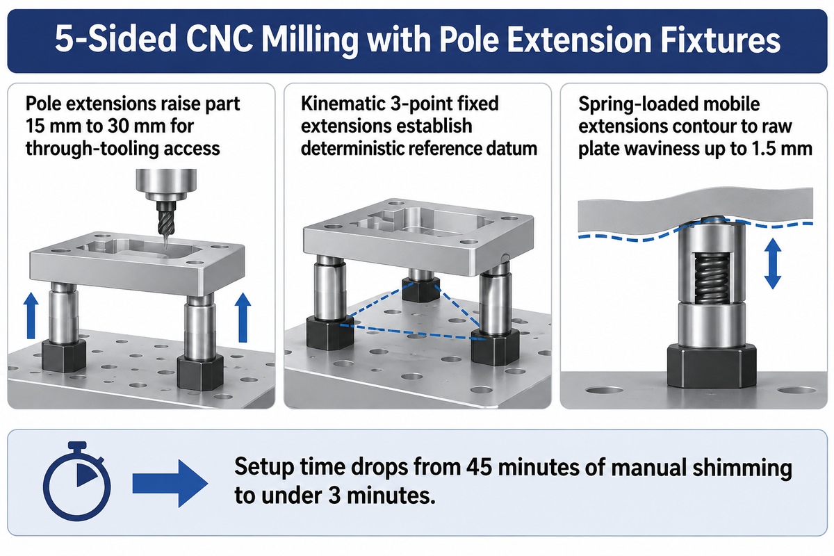
Through-Drilling and Cutter Clearance: If an operator drills through-holes or mills full-depth exterior contours directly on a solid magnetic chuck face, cutting tools will plunge into the chuck top plate, cutting into copper coils, damaging magnetic poles, and ruining table hermetic seals. To avoid this, machinists use raised pole extensions– hardened steel blocks that are bolted onto each active chuck pole. Pole extensions raise the workpiece 15 mm to 30 mm above the chuck body, creating complete clearance for through-drilling, bottom chamfering, and thread tapping without risking table contact.
Eliminating Distortion with Self-Shimming Fixtures: Raw billets and flame-cut plates are never perfectly flat; they exhibit bowing, surface waviness, and thickness variations up to 1.5 mm. If an operator activates a magnetic chuck beneath a bowed plate resting on a flat face, the magnetic pull pulls the high spots down elastically against the bed. The operator mills the top face flat, but when the chuck is demagnetized, the internal elastic stress releases, causing the plate to spring back like a bow, destroying final part parallelism. To solve this problem, engineers configure a kinematic 3-Point Fixed + Mobile Self-Shimming Array:
- Three Fixed Pole Extensions: Three solid steel pole extensions are placed at widely spaced coordinates on the table to create a deterministic, non-rocking, kinematic reference plane (the 3-point datum).
- Mobile Spring-Loaded Pole Extensions: The remaining active poles have mobile extensions with internal compression springs and conical wedge locks. The mobile extensions move up and down as needed, to accommodate the raw part profile without exerting pressure.
- Pulse Activation Lock: After the part is seated, the controller sends a 1 second magnetization pulse. As the mobile extensions make contact with the billet, magnetic flux bridges close mobile extension circuits, and the internal wedge components draw together, locking the mobile extensions at their final position. The workpiece is clamped solid across all contact points, eliminating internal bending stresses.
In the highest quality machine shops with either a horizontal or vertical CNC machining center, this methodology for pole extensions has reduced raw billet setup times from 45 minutes of manual shimming and dial indicating to under 3 minutes, all while keeping part finish tolerances within tight tolerance machining limits.
Can you machine through-holes while using a magnetic chuck?
Yes, you can machine through holes and through pockets on a magnetic chuck by employing this method of elevating the workpiece using spring-loaded pole extensions. Bolting 15 mm to 30 mm hardened pole blocks directly onto active poles lifts the part above the table bed, providing ample clearance for drills, taps, and contouring end mills to break through completely without touching or damaging the chuck top plate.
5. Precision Surface and Rotary Grinding: Flatness Control, Heat Dissipation, and Thin Parts
High-production rotary Blanchard grinding uses magnetic workholding to achieve micron-level flatness and parallelism. Grinding wheels induce high surface speeds with shallow depths of cut. As a result, mechanical edge clamps localize compressive stresses and cause thin stock to buckle upward. Fine-pole magnetic chucks hold plates evenly flat across their entire surface.
Precision grinding of thin plates presents unique thermal and mechanical challenges that the operator must control to minimize detrimental effects to part surface quality.
Preventing Heat-Induced Chuck Crowning: As noted in our architecture comparison, traditional electromagnetic chucks generate continuous internal heat. Steel has a thermal expansion coefficient of approximately 11.5 μm/m/°C. On a 1000 mm × 500 mm electromagnetic table, continuous 15°C temperature rise causes the center of the chuck to expand upward by 10 μm to 20 μm relative to the cooler outer edges. Grinding a plate flat on a crowned chuck produces a workpiece with a concave bottom and convex top once the chuck cools down. Precision toolrooms running fine-tolerance work (DIN 8632 standards) prevent this by switching to cold-operating EEPM grinding chucks or installing closed-loop chiller lines that circulate temperature-controlled coolant through the chuck housing.
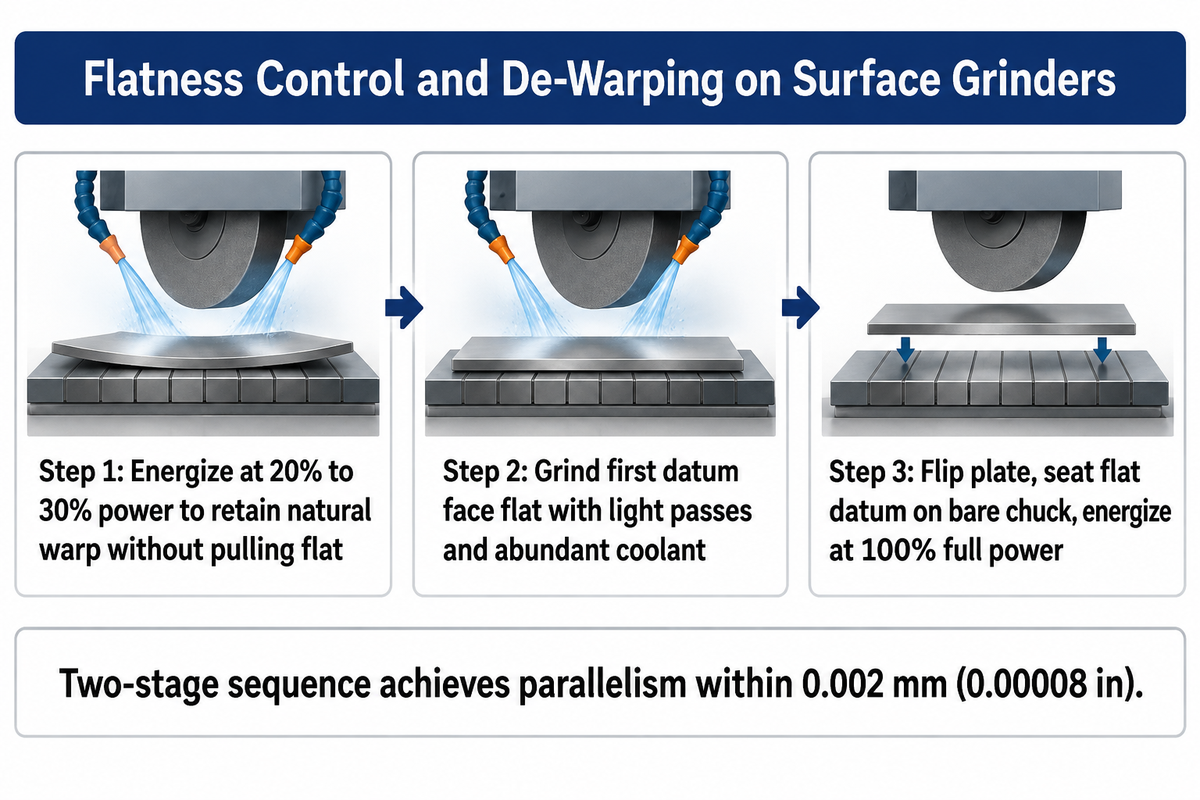
Feeler Gauge Shimming for Bowed Thin Plates: When surface grinding thin tool steel plates (e.g., 3 mm to 6 mm thick O1 or D2) that have been heat-treated, the plates frequently arrive with slight quenching warps. Placing the warped plate directly onto a high-power magnetic chuck pulls the bow flat elastically; grinding the exposed face and demagnetizing produces a plate that springs right back into its warped shape. To grind a warped part dead flat:
- Place the concave side down onto the magnetic chuck.
- Add brass or steel feeler gauge shims to the high edges and corners of the plate until the plate sits level and stable (i.e. not rocking or wobbling) under finger pressure.
- Activate the chuck at 20% to 30% holding power to ensure the magnet holds the part and pulls out the natural warp.
- Take a few light grinding passes with flood coolant to establish a true, flat reference plane.
- Demagnetize, flip the plate over, seat the freshly ground flat face directly onto the bare chuck, energize at 100% full holding power, and grind the opposite face parallel. This proven sequence achieves parallelism within 0.002 mm (0.00008 in).
Rotary Turning and Ring Grinding: Thin-walled bearing rings and gear blanks secured by radial pole magnetic chucks in large vertical turning lathes and cylindrical rotary grinders, provide good alternatives to three- and six-jaw scroll chucks, which create three- and six-point trilobing, respectively, on thin rings. A radial magnetic chuck clamps the entire ring face uniformly, eliminating roundness errors during internal and external diameter turning.
Why do thin parts warp on a magnetic surface grinder?
Thin parts may warp on the surface grinders because magnetic pulls may elastically flatten thin sheet stock against the chuck face. Once the stock is ground flat and released, the sheet may spring back into a warped state. Continuous buildup of heat from pure electromagnets may cause a chuck to “bake”, increasing it’s diameter in the center. This may cause thin stock to grind hollow. Skim passes and using a cold EEPM may help.
6. Workpiece Material Limits: Ferromagnetic Permeability, Thickness Saturation, and Scale
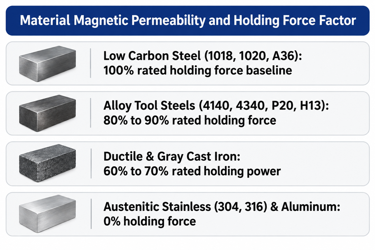
A magnetic workholding fixture may only clamp materials which provide a magnetic flux path. The clamping performance and magnetic performance of a magnetic chuck is dependent upon material thickness, magnetic permeability and contact face air gaps.
Material Magnetic Permeability (K_material): The flow of Magnetic Flux through a material is dependent on its relative Permeability (μr). Pure low-carbon mild steel (as in AISI 1018 or 1020) offers the best magnetic path, and thus sets the standard 100% baseline for rated holding power. As the carbon content and other alloying elements (such as chromium, nickel, manganese) and hardness increase, magnetic permeability decreases significantly:
- Low Carbon Steel (1018, 1020, A36):100% rated holding force. Exceptional saturation, minimal flux leakage.
- Alloy Tool Steels (4140, 4340, P20, H13):80% to 90% rated holding force. Readily clamped for aggressive milling.
- High Carbon & Tool Steels (D2, O1, M2):70% to 80% rated holding force. Higher reluctance requires clean contact surfaces.
- Ductile & Gray Cast Iron:60% to 70% rated holding power. Carbon flakes and graphite nodules disrupt magnetic pathways.
- Ferritic & Martensitic Stainless Steels (410, 420, 440C):40% to 55% rated holding force. Magnetic, but requires conservative cutting feed rates.
- Austenitic Stainless Steels (304, 316) & Aluminum / Brass / Titanium:0% holding force. Completely non-ferromagnetic; can’t be held directly by magnetic fields.
The Devastating Effect of Air Gaps (K_gap): Air is a poor magnetic conductor, with a magnetic permeability thousands of times less than steel. Any physical gap between the chuck top plate and the workpiece face introduces extreme magnetic reluctance into the circuit, causing flux lines to disperse before entering the part. Common shop contaminants act as catastrophic air gaps:
| Interface Condition / Air Gap Distance | Typical Shop Floor Cause | Remaining Magnetic Holding Power (%) | Effective Clamping Pressure (at 160 N/cm² base) |
|---|---|---|---|
| 0.00 mm (Direct metal-to-metal) | Ground clean plate resting on dressed chuck | 100% | 160 N/cm² (232 psi) |
| 0.05 mm (0.002 in) | Light oil film, micro-burrs, fine grinding dust | 85% – 90% | 136 – 144 N/cm² (197 – 209 psi) |
| 0.10 mm (0.004 in) | Coolant dried residue, light surface rust | 70% – 75% | 112 – 120 N/cm² (162 – 174 psi) |
| 0.25 mm (0.010 in) | Hot-rolled mill scale, unground flame-cut slag | 45% – 50% | 72 – 80 N/cm² (104 – 116 psi) |
| 0.50 mm (0.020 in) | Paint coating, severe billet warp, heavy chip debris | 20% – 25% | 32 – 40 N/cm² (46 – 58 psi) |
| 1.00 mm (0.040 in) | Part bridge gap across unground casting surface | <10% | <16 N/cm² (<23 psi) — Extreme Hazard |
0.25 mm (0.010 in) of mill scale or shop contamination reduces holding force by over half. Operators wire-brushing or skim-millging the bottom of the billets before full-power magnetic milling is standard practice.
Holding Non-Ferrous Materials on Magnetic Tables: When a shop standardizes its CNC tables with magnetic chucks, machinists need to mill non-Ferromagnetic parts like aluminum plates, bronze bushings or 316 stainless blocks. Rather than removing the magnetic chuck from the machine table, operators can apply these three effective hybrid workholding methods:
- Steel Sub-Plate Tooling:Clamp the non-magnetic part in a low-profile aluminum or steel fixture plate which is secured by a thick 1018 steel base. The magnetic chuck clamps the steel sub-plate with maximum pull force, securing the assembly.
- Threaded Pole Extension Clamping:Recently, EEPM pole extensions have included an M8 or M10 central thread. Low profile toe clamps, whether standard or pitbull, can be attached to the pole extensions and provide a rapid modular T-slot grid conversion to the magnetic table.
- Magnetic-Vacuum Conversion Plates: Modular vacuum sub-plates have a bottom grid of ferromagnetic steel and vacuum gasket channels on top. The magnetic chuck attaches the vacuum plate to the machine, and a thin aluminum or composite plate is held against the vacuum gasket by a second vacuum pump.
Can you clamp aluminum on a magnetic chuck?
Non-ferrous aluminum cannot be clamped directly because it possesses zero magnetic permeability. Machinists hold aluminum by mounting parts on steel sub-plates, using edge clamps in pole holes, or using modular vacuum plates.
7. Calculating Magnetic Holding Force Against Cutting Loads: The 5-Factor Protocol
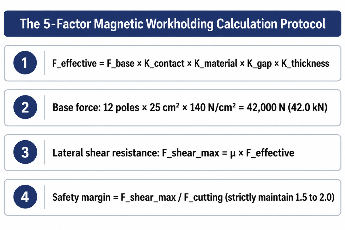
To prevent workpiece movements and Cutter Collisions when machine components, manufacturing engineers can’t solely depend on speculation and generic manufacturer. The 5-Factor Magnetic Workholding Protocol provides a verifiable systematic method to determine the holding force of magnetic and cutting shear margins of tool before any cuts are made.
The 5-Factor Protocol Formula:
F_effective = F_base × K_contact × K_material × K_gap × K_thickness
Step 1: Calculate Base Clamping Force (F_base)
Multiply the active pole contact area (A) by the manufacturer’s rated force density (commonly 120 to 160 N/cm² for EEPM milling chucks). For example, a steel mold block resting across 12 active square poles (each 50 mm × 50 mm = 25 cm²) provides an active contact area of 12 × 25 cm² = 300 cm². At a base rating of 140 N/cm²:
F_base = 300 cm² × 140 N/cm² = 42,000 N (42.0 kN / 9,440 lbf)
Step 2: Apply Contact Area Factor (K_contact)
If pole extensions cover 100% of the active pole face, K_contact = 1.0. If part overhang or relief cutouts reduce pole contact to 80%, K_contact = 0.80.
Step 3: Apply Material Permeability Factor (K_material)
Refer to our permeability ratings: mild steel = 1.0; 4140 pre-hardened alloy steel = 0.85; ductile cast iron = 0.65; 420 stainless steel = 0.50.
Step 4: Apply Air Gap Reluctance Factor (K_gap)
For ground, deburred surfaces, K_gap = 0.95. For clean, saw-cut or wire-brushed raw billet surfaces with slight surface roughness, K_gap = 0.70. For hot-rolled plate with scale, K_gap = 0.50.
Step 5: Apply Thickness Saturation Factor (K_thickness)
If workpiece thickness exceeds the pole saturation threshold (e.g., >15 mm for 50 mm square poles), K_thickness = 1.0. For a 10 mm plate on 50 mm poles, K_thickness = 0.70. For a 6 mm plate, K_thickness = 0.45.
Calculating Lateral Shear Resistance and Cutting Safety Margins
Workpieces on a magnetic chuck don’t fail by lifting vertically; they fail when aggressive horizontal cutter feeds overcome lateral sliding friction. The maximum lateral shear resistance (F_shear_max) is:
F_shear_max = μ × F_effective
Where μ is the interface friction coefficient (use μ = 0.15 for flood-coolant milling on ground pole extensions). If our calculated effective vertical clamping force is F_effective = 25,000 N:
F_shear_max = 0.15 × 25,000 N = 3,750 N (3.75 kN)
Next, determine dynamic tangential cutting force (F_cutting) using the Kienzle specific cutting force formula for your milling cutter diameter, tooth count, feed per tooth, and radial depth of cut. If heavy face milling generates a peak cutting force of F_cutting = 2,200 N, the dynamic safety margin is:
Safety Margin = F_shear_max / F_cutting = 3,750 N / 2,200 N = 1.70
The Golden Workholding Rule: A minimum safety margin of 1.5 to 2.0 is strictly required for unblocked magnetic milling. If the base material requires aggressive roughing and cutting loads go beyond this safety margin, the machinist must make mechanical positive stops (side stop blocks bolted to the chuck) to physically absorb lateral cutting thrust, and let the magnetic chuck focus on Z-axis vibration damping and face pull-down.
How do you prevent a part from sliding on a magnetic chuck during milling?
To overcome the forces that act laterally against the cut, machinists install positive stops against the workpiece edges. Dynamic cutting loads are determined by the Kienzle equations, and side stops are designed to absorb lateral cutting thrust. With magnetic workholding pulling down in a perpendicular direction and the sliding resistance limited to friction (μ ≈ 0.15 with coolant), side stops absorb the majority of the lateral cutting thrust and magnetic milling pull dampens vibration, allowing stability in the Z-axis.
8. Machine Shop Troubleshooting: Residual Magnetism, Demagnetizing Cycles, and Chip Clearance
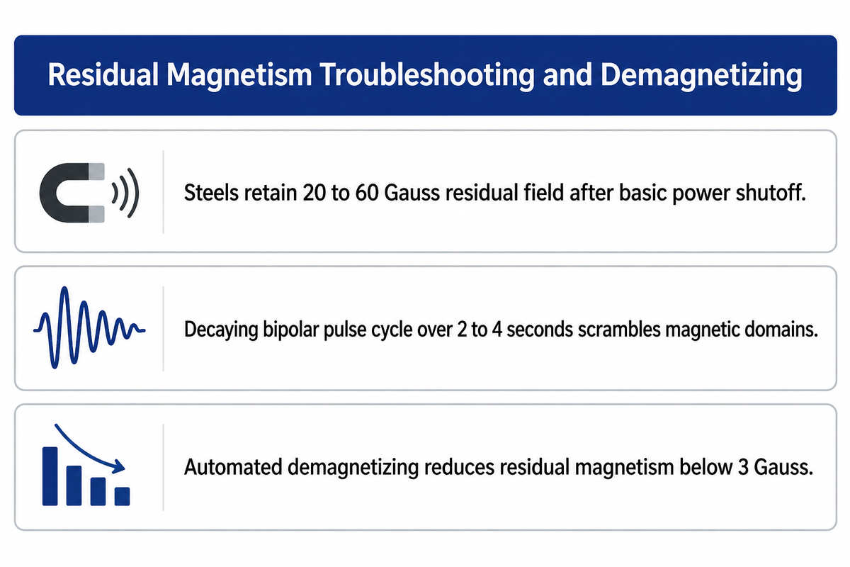
magnetic workholding speeds up part setup, and while chip metal is packed and cutter is worn, machine shops often experience challenges related to residual magnetism. Operators develop a quick understanding of the symptoms and implement permanent solutions.
Residual Magnetism and Chip Packing: When a hardened alloy steel workpiece is clamped and machined on a powerful magnetic chuck, the magnetic domains within the steel align with the external field. After the chuck is switched off, high-coercivity steels retain significant residual magnetism (usually in the range of 20 to 60 Gauss). If the operator removes the part from the table without proper demagnetization, several serious problems occur:
- Ferromagnetic milling chips adhere tightly to the part surface and blind holes, and make deburring and cleaning very difficult and time-consuming.
- magnetized chips during subsequent CNC turning or grinding operations stick to the cutting edge of the tool, causing recutting of chips and micro-chipping of carbide inserts and tool edge failure.
- Residual magnetism affects downstream Wire EDM operations by causing deflection of the ionized spark gap and violates aerospace/medical inspection standards which require a residual field strength less than 2 to 3 Gauss.
Understanding Modern Demagnetizing Cycles: Basic magnetic chucks simply turn off current, leaving maximum remanence in the part. Modern EEPM and electromagnetic chuck controllers feature automated, multi-step decaying bipolar demagnetizing cycles. Over a 2 to 4 second cycle, the controller fires a rapid series of alternating positive and negative current pulses of progressively decreasing amplitude (e.g., +100%, -85%, +70%, -55%, +40%, -25%, +10%, 0%). This decaying alternating field cycles the workpiece through shrinking hysteresis loops, completely scrambling the internal magnetic domains and reducing residual field strength to below 3 Gauss (verified with a calibrated Hall-effect Gauss meter).
Managing Milling Chips and Cutter Magnetization: In heavy CNC milling, operators may observe that high-speed face mills or carbide end mills become magnetized, pulling hot chips into the cutter body. This symptom is typically caused by flux overshoot, i.e., when the workpiece is too thin for the pole pitch and magnetic flux loop through the air above the part, where cutters are spinning. To prevent magnetization of cutters: increase part elevation to provide a greater air buffer, make sure the part has minimum thickness required, and position coolant nozzles to wash chips away from cutting flutes.
How do you completely demagnetize a machined part?
Complete demagnetization of a machined part requires that the part be exposed to a decaying alternating magnetic field, causing the material to cycle through a shrinking hysteresis loop. EEPM controllers run a decaying bipolar pulse cycle over 2 to 4 seconds, which decreases the polarity from 100% to 0%, to reduce the level of magnetization to less than 3 Gauss. For more sensitive components, passing the part through an AC tunnel degausser across one face and sides removes any surface fields.
9. Magnetic Chuck Maintenance, Top Plate Dressing, and Equipment Sizing Checklist
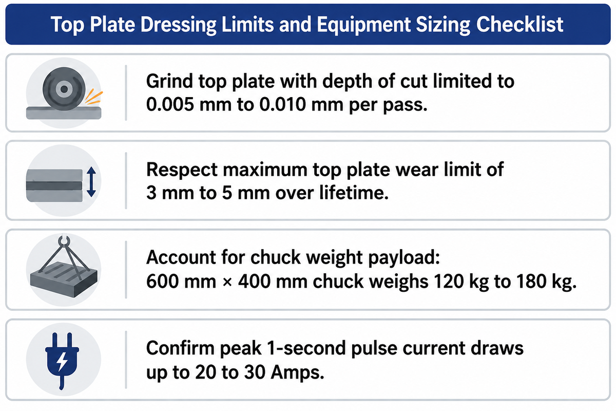
machined tool accessories are machine, sealed magnetic chucks designed for decades of use. Maintaining micron-level precision in Soukupunipun results requires strict adherence to procedures during top plate dressing and the rigorous technical assessment of equipment purchased for machine tools.
Magnetic Chuck Top Plate Dressing and Skim-Grinding: Over months of heavy machining, burrs, stains, and scratches collect on the top surface of chucks. To restore the absolute flatness of the machine axes, and parallelism relative to the machine, operators of heavy CNC milling machining centers perform periodic skim dressing.
- Mount the chuck firmly on the machine table and connect the controller cables.
- Energize the chuck to full holding power! Mandatory step: Dressing an un-energized chuck results in flatness loss because of micro-mechanical movement of magnet poles under magnetic tension. Always dress in the clamped state.
- Apply ample coolant flood. Never grind a magnetic chuck face dry. Dry grinding produces localized friction heat that brings the steel poles and brass separator bars to an unequal expansion and contraction, causing the bed to warp and melting the epoxy seals.
- Take ultra-light grinding passes using a vitrified, open-structure wheel (e.g., 46-grit aluminum oxide). Limit depth of cut to maximum 0.005 mm to 0.010 mm (0.0002 in to 0.0004 in) per pass, sparking out completely on the final pass.
- Never mill or dress the top poles of the manufacturer more than the specified maximum top plate wear (which is usually stamped on the edge of the chuck, 3 mm to 5 mm max total wear across the life of the chuck). Dressing more than this exposes the internal magnet and permanently destroys the table’s hermetic seals.
Industrial Magnetic Chuck Procurement & Integration Checklist
Prior to specifying a new magnetic workholding system for a vertical machining center, or CNC lathe, review the following 7 engineering checkpoints:
- Machine Table Weight Payload: Solid steel EEPM chucks are heavy (a 600 mm × 400 mm chuck weighs approximately 120 kg to 180 kg). Verify that the combined weight of the magnetic chuck, pole extensions, and heaviest workpiece doesn’t exceed the machine table’s maximum rated payload capacity.
- Controller Electrical Voltage & Pulse Current: Confirm facility electrical supply matches the pulse controller (standard units require 200V, 240V or 380V, 480V 3-phase AC). While continuous consumption is zero, the 1-second pulse draws instantaneous peak currents up to 20 to 30 Amps.
- CNC M-Code Safety Interlocks: Don’t use manual push button controllers on automated CNC machines. A properly configured controller must integrate into the CNC machine PLC via dry contact relays and interlock with the machine E-Stop, meaning the spindle can’t start unless the chuck controller confirms full saturation. Cutting must stop, immediately, if a fault is detected.
- Pole Pitch vs Typical Part Spectrum: Audit your shop’s component portfolio. If 80% of jobs are thin plates (<8 mm), order fine-pole systems (1.5–4 mm pitch). If jobs are large mold dies, heavy billets, or structural plates (>25 mm), order 50 mm or 70 mm square-pole EEPM chucks.
- Pole Extension Kit Completeness: Each order must contain a complete set of fixed datum extensions, a complete set of mobile extensions, and a complete set of edge stop blocks, to accommodate irregular raw material.
- Sub-Plate Interface Compatibility: In facilities using modular quick change pallet systems (such as zero point clamping receivers), it’s recommended to order magnetic chucks with pre-machined zero point pull stud patterns on the bottom for quick, repeatable changeover.
- Machine Builder Integration: Work with trusted machine tool manufacturers who can integrate Factory workholding. Leading builders of ANTISHICNC metalworking machines provide Factory configured machine tables, pre-wired Controller channels, and integrated M-Code macros to support workholding commissioning on their Tornos CNC.
When selecting machines and fixturing for your manufacturing floor, cross-reference our guides on CNC turning definitions, lathe chuck types, y conversational CNC programming to configure balanced, high-efficiency production cells across all your turning, milling, and grinding operations.
How often should a magnetic chuck be ground or dressed flat?
A magnetic chuck should be skim dressed when runout, scratches or parallelism errors are seen on the working surface and is more than 0.005 mm to 0.010 mm. A severe tool collision can also warrant a skim dressing. For standard production milling and grinding, dressing once or twice a year restores flatness. Always energize the chuck to 100% power and use plenty of Flood coolant when dressing.
FAQ (Frequently Asked Questions)
Can magnetic workholding replace traditional milling vises completely?
While it’s true that Magnetic workholding can’t fully replace traditional vises for small prismatic parts and non-ferrous operations that require high side clamping, for large plates, mold bases and 5-sided machining, magnetic chucks outperform vises and eliminate clamping distortion, offering full access to cutter, and thereby reducing turnaround time for machining operations.
Does magnetic workholding damage CNC machine spindles or bearings?
No. A properly designed magnetic chuck creates a shallow closed magnetic circuit that confines flux solely between North and South poles alternatively positioned in the workpiece and chuck top plate. Flux doesn’t spread to the machine table, ballscrews or spindle bearings and thus, ensures no magnetic or electrical interference with machine motion components.
What is the difference between an electro-permanent magnet and a pure electromagnet?
An electromagnet requires constant direct current electrical power to maintain its magnetic field, generating continuous coil resistance heat that induces thermal expansion across the chuck bed. In sharp contrast, an electro-permanent magnet requires electrical energy only for a single 1-second switching pulse to reverse internal Alnico magnet polarity, maintaining full rated clamping force passively with zero electricity, zero heat generation, and zero thermal drift.
How do you clamp non-magnetic materials like brass or titanium on a magnetic table?
Non-ferrous materials can’t be clamped by magnetic flux. Non-magnetic parts can be held by steel backing plates, mechanical toe clamps, or by use of modular magnetic vacuum-hybrid plates that switch vacuum channels and are placed on the magnetic base.
How does cutting coolant affect magnetic clamping force?
Cutting fluid doesn’t reduce magnetic pull force because magnetic flux easily penetrates liquids. As such, coolant is used to create a hydrodynamic boundary layer. This lowers the friction coefficient between the workpiece and the steel chuck face by 30% to 40%. As a result, lateral sliding resistance is equal to normal magnetic pull force multiplied by the friction coefficient. Milling cuts with coolant require the use of mechanical edge stops, nesting pins, or high-friction hardened pole extensions to prevent part movement during a cut.
Referencias y fuentes
- ISO 16156 Machine tools, Safety, Safety requirements for the design and construction of work holding chucks
- Maxwell Pull Force Between Magnetized Surfaces, Princeton University Department of Physics
- Electro-Permanent Magnetic Clamping System with Reversible Polarity, US Patent 4,507,635
- Modern Machine Shop – The Basics of Magnetic Workholding
- Magnetic Workholding and Dynamic Cutting Shear Margins, Production Machining
- DIN 8632 Machine Tools Testing, Surface Grinding Machine Table Accuracies