


GD&T basics come down to a single idea: a drawing should communicate how a part needs to function, not only how big it’s. Geometric Dimensioning & tolerancing (GD&T) is the symbol language that engineers put on prints and 3D models to e×press acceptable variation in form, orientation, location, and runout. If you read or produce engineering drawings – or you machine to them – this guide runs you through every building block: datums, the feature control frame, all 14 symbols (and why two of them disappeared in 2018), material condition modifiers, and how to read a real callout.
Quick Specs: GD&T at a Glance
| Governing standard (USA) | ASME Y14.5-2018 (replaced Y14.5-2009) |
| Governing standard (ISO) | ISO 1101:2017 (GPS — geometric tolerancing) |
| Geometric symbols | 14 under 2009 → 12 under 2018 (concentricity & symmetry removed) |
| Five control categories | Form, Profile, Orientation, Location, Runout |
| Reference framework | Datum Reference Frame = 3 mutually perpendicular planes |
| Default measuring conditions | 20 °C / 101.3 kPa unless stated |
What Is GD&T? (And Why Engineers Use It)

GD&T is a system used to describe and communicate both the nominal geometry of a part, along with the variations in geometric form that are acceptable for the part to continue to work properly. Instead of detailing a part with solely linear dimensions and limits, GD&T incorporates a series of symbols to communicate what is functionally important-that a surface will remain flat, a bore round, or a pattern of holes aligned with its mating part.
In the U.S., the system is standard; however, in other parts of the world, the system is referred to as ISO 1101:2017.
GD&T is implemented because a standard dimension on a print may be technically in-spec but effectively non-functional. A tabletop that only shows the height variation between 750mm and 780mm, for example, might only measure 750mm at one end and 780mm at the other (a 30mm slope) yet still be labeled as within tolerance. However, a flatness control defines what actually matters, i.e., how the surface must act, directly. Purpose behind GD&T is that it communicates a single standard requirement to the designer, manufacturer, and inspectors, avoiding ambiguity by focusing on functional requirements as opposed to manufactured form. Textbooks commonly describe this same principle, including one explaining GD&T as the language for engineers to express a true profile with a zone around it and the corresponding tolerance limits. Likewise, in teaching notes from the Milwaukee School of Engineering, GD&T is described as defining the ideal form with limits.
This process isn’t intended as extra paperwork; rather, GD&T ensures that a part is correct both dimensionally and functionally. Components that are manufactured with GD&T-driven controls must remain in alignment for the assembly to function correctly and effectively. The print is the blueprint; the GD&T-control communicates the intention behind the design, which is critical in the case of precision manufacturing.
GD&T vs. Traditional (Coordinate) Tolerancing: The Real Difference

coordinate tolerancing. Controls form and locate the feature with X, Y datums and tolerances. While this approach appears to be quite specific in relation to position, it doesn’t consider actual form; if you place the center of the feature exactly on point “zero,” the hole is free to go up, left, right, or even to be noncircular inside a 20mm-square area centered on the target position.
The Aha! that made GD&T. Stanley Parker, working with naval ordnance around 1940, realised round bosses and holes needed a round tolerance zone, not a square one. It ended up as a military standard in the 50s, and was the precursor of today’s true position.
Replace a square coordinate zone with a cylindrical position zone that would fit inside the diagonal, and the useful area jumps by almost 57%. Why? A circle that circumscribes a square has an area of /2 1.571 times the area of the square – roughly 57% more area – for the same functional fit. Now there’s tolerance you were “losing” with that dimensioning!
So which should you use? Both. Plus/minus tolerancing works just fine for feature size; GD&T shows its real value for features that need to align, mate, or spin. Follow this decision guide.
| Situation | Use ± Coordinate | Use GD&T |
|---|---|---|
| Overall length / width / a simple slot width | ✔ Yes — size only | Not needed |
| Hole pattern that bolts to a mating part | Risky (square zone) | ✔ Position with datums |
| Sealing or bearing face must stay flat | Cannot express it | ✔ Flatness |
| Rotating shaft must run true | Cannot express it | ✔ Runout to a datum axis |
The Three Building Blocks: Datums, Feature Control Frames & Basic Dimensions

Before any of these symbols matter, three things need to be in place. Get these three elements right and the rest of GD&T tends to follow:
1. Datums and the datum reference frame (DRF). A datum (there can be primary, secondary and tertiary datums) answers, “What am I measuring against?” Each of these datum surfaces defines a plane, and together they define a reference coordinate system against which all other controls on the part will be measured. (That whole system of three perpendicular datum surfaces is called a datum reference frame). A datum feature (the actual hole, edge, or surface on the part used to create the primary, secondary, and tertiary datums) should ideally be a part of the datum features the part would normally contact in use.Choosing the right datum feature is arguably the single most important step in defining GD&T.
2. The feature control frame (FCF). This is the standard boxed symbol. Reading left to right it’s composed of: The geometric control symbol itself (i.e. straightness, flatness, position). Followed by the shape and value of the tolerance zone (the tolerance zone – if the tolerance zone has a leading sign the zone is cylindrical). This may or may not be followed by a material modifier. This will be followed by one or more datum references (indicating which of the established datum planes(s) define the zone, again listed in order of primacy). A single feature control frame will control a single geometric characteristic of a single feature. You can apply multiple feature control frames to the same feature to control more than one characteristic.
3. Basic dimensions. A basic dimension is an theoretically exact value (and always appears in a box). It establishes an exact location, orientation, or angle – without tolerances. These basic dimension’s establish the true theoretically perfect geometry, not the allowable tolerance, which is handled by the feature control frame (FCF). One common example is a true position hole pattern where each location is defined by a boxed basic dimension and then the position itself is defined by the allowable deviation from true position (defined by the FCF).
What is the 3-2-1 rule for GD&T?
The 3-2-1 rule The rule is that you fully constrain a prismatic part against the datum reference frame using six contacts.The datum primary hits 3 (one translate and two rotate degrees of freedom).The datum secondary hits 2(one of each, again)and the datum tertiary hits the last 1.Three plus two plus one makes six total, you’ve locked up the part’s movement into one repeatability when you inspect it. Iowa State University’s machine design classes teach this same primary/secondary/tertiary sequence for positional inspections.Get the sequence wrong, and it rocks and wobbles to another position, changing your numbers.
The 14 GD&T Symbols, Grouped Into 5 Categories

Don’t Memorize. Map. Beginners try to learn all of the symbols as they appear on a blueprint, but that’s overwhelming and unnecessary. Instead, learn them as five families-engineers call this “The 5-Category Map”. Once you know which family a symbol belongs to, you intuitively know where it fits on the blueprints and whether it will need a datum.
What are the 14 symbols in GD&T?
According to ASME Y14.5-2009, there were 14 geometric characteristic symbols across these five categories: Form (straightness, flatness, circularity, cylindricity),profile(lines, surfaces),Orientation (angularity, perpendicularity, parallelism), Location (position, concentricity, symmetry), and runout(circular, total). ASME Y14.5-2018 did away with the entire concept, terms and symbols of concentricity and symmetry, bringing it down to 12 remaining symbols. Full map:
| Category | Symbol & Name | Controls | Datum? |
|---|---|---|---|
| Form | — Straightness | A line or axis is straight | No |
| ▱ Flatness | A surface’s high/low spots | No | |
| ○ Circularity | Roundness of a cross-section | No | |
| ⌭ Cylindricity | Round + straight along a barrel | No | |
| Profile | ⌒ Profile of a Line | A 2D cross-section vs. true profile | Optional |
| ⌓ Profile of a Surface | A whole 3D surface vs. true profile | Optional | |
| Orientation | ∠ Angularity | A feature at an angle to a datum | Yes |
| ⊥ Perpendicularity | 90° to a datum | Yes | |
| ∥ Parallelism | Parallel to a datum | Yes | |
| Location | ⌖ Position | Location of a feature/pattern | Yes |
| ◎ Concentricity (removed 2018) | Axis vs. datum axis | Yes | |
| ⌯ Symmetry (removed 2018) | Symmetry across a datum plane | Yes | |
| Runout | ↗ Circular Runout | Wobble at one cross-section | Yes |
| ⌰ Total Runout | Wobble across the whole surface | Yes |
Note that the physical shape of symbol glyphs differ on many computer fonts, so it’s the symbol category and the text symbol itself that define its meaning for blueprints. Notice how on ASME Y14.5-2018, the Datum column gives you a significant shortcut; any Form control symbols never need a datum because the part contains its own reference feature(s), while every symbol in orientation, Location and runout require a datum.
Form Controls: Flatness, Straightness, Circularity, Cylindricity

Control shape of individual features. Form controls police the shape of a single feature against itself, thus, requiring no datum. A flatness (planarity) check involves establishing two parallel planes at a specified tolerance apart, then making sure the entire measured feature lies within those boundaries. This is perfect control for an internal surface or a lapped surface, say an ID O-ring Groove or a sealing surface. A similar check for a line element or axis, straightness, functions just as its name imply. circularity (circularity) makes a check of a single cross section of a hole or shaft, while cylindricity (cylindricity) is more stringent because it covers roundness, planarity and taper along the entire length of a cylinder-it’s therefore the most expensive form check.
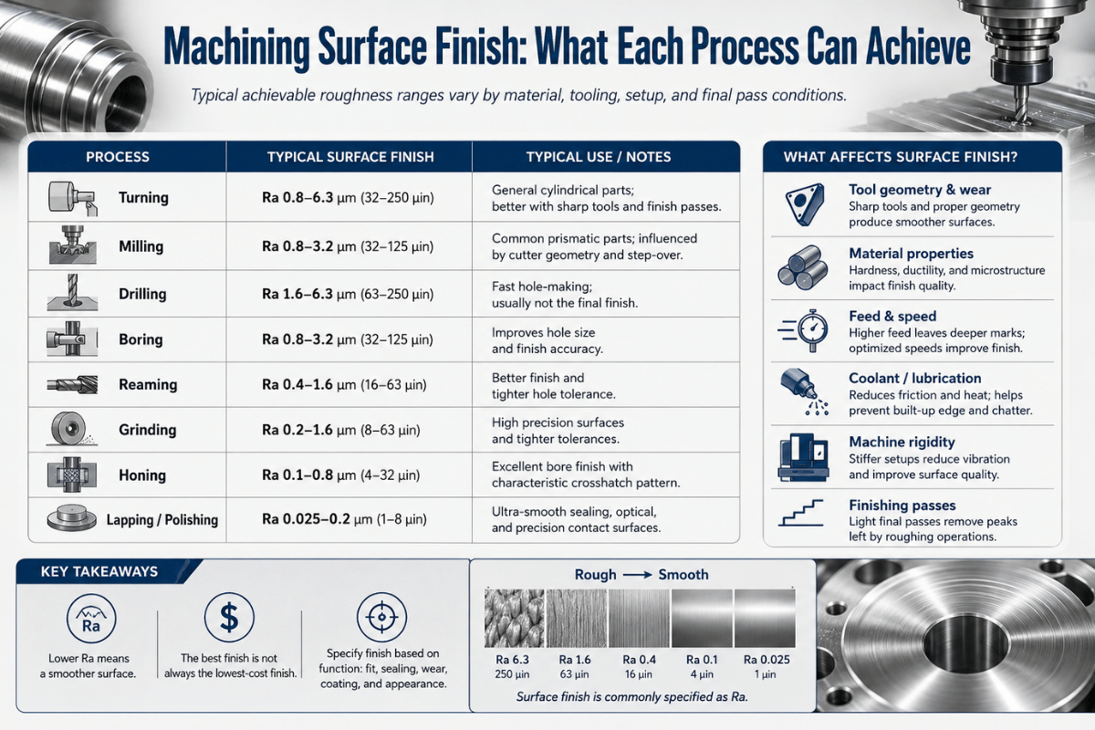
Don’t Over Specify form. If the geometry requires tightness at the ID for a seal, or at the shaft OD for a bearing, don’t specify a flatness as anything less than 0.001 inches or it can’t practically be measured even if the parts can be held in their form tightly. Roundness, which checks a section, needs to take into consideration any of the other tighter form controls you might have on a shaft such as Tightness cylindricity. Specify form controls that your machining operations can realistically hold. Precision surface grinding readily holds flatness to tenths of thousandths (low microns); Cylindrical grinders consistently hold tight roundness and cylindricity on shaft geometries-yet the callout must also allow for adequate fixture locations as well as thermal variation in ambient conditions(don’t forget the 20 C)if the callout for flatness callout is tighter than your surface grinder can repeatability create, you’ve only put it on paper to have parts scrap to your specifications. The call out need to relate to your machine capability, not just your hopes.
Don’t be that person who stacks tight flatness controls and Tightness parallelism on the same face. There’s a redundancy to parallelism; the parallelism call out has its own form requirements for angularity; therefore it also implicitly sets the flatness control also tight along with any straightness requirement. Always check for redundancies in your feature controls and remove extra unnecessary ones. Every single added form, Orientation, or Location control that doesn’t directly support product functionality will add cost and inspection time for the team.
Orientation & Location Controls: Parallelism, Perpendicularity, Position

The rest of these controls also point to datums, because “at an angle” or “in the right place” only means something relative to something else. Angularity holds a feature at a basic angle to a datum, perpendicularity is angularity’s 90 special case, parallelism holds a feature parallel to a datum, and for an axis it can use a cylindrical zone by adding a in front of the value.
Position (true position) is the workhorse- the most-used control in all of GD&T. It locates a feature or a whole pattern using boxed basic dimensions, then allows deviation inside a usually-cylindrical zone referenced to the datums. This is exactly where the 57% area advantage from earlier pays off: a round position zone accepts more good parts than the square box for the same fit.
“A cylindrical position callout almost always needs all three datums to fully constrain the zone. Under-constrain it with only one or two and the part can rock or rotate, and your measurement won’t repeat- which is the number-one reason beginners ‘fail’ good parts.”
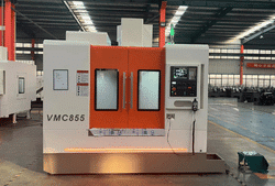
Where do these controls get produced and verified? On the machines that locate features to each other- a CNC lathe machine for coaxial turned features, or a vertical machining center for hole patterns. Picking datum features that match the part’s mating interfaces, not the easiest faces to touch off, is what makes position tolerances achievable on the floor.
Profile & Runout Controls (and the Symbols ASME Deleted)

profile of a surface is the most powerful single control in GD&T: it defines a 3D tolerance zone- two offset surfaces- that the actual surface must fall between, and it can stand in for size, form, orientation, and location all at once. That’s why it dominates modern model-based drawings. profile of a line does the same job on individual 2D cross-sections.
runout controls rotating parts against a datum axis. circular runout checks “wobble” at a single cross-section as the part spin; total runout checks the entire surface at once, capturing straightness, taper, and profile error together- ideal for bearing journals and seal surfaces produced on a CNC cylindrical grinder.
If you learned GD&T from an older textbook, you may reach for concentricity () or symmetry(). ASME removed both in Y14.5-2018 because they were hard to measure consistently and were routinely misused. Fixing it’s straightforward: use position or runout to control coaxiality, and profile or position to control symmetry-like requirements. They do the same job with zones you can actually verify on a CMM.
Material Condition Modifiers (MMC, LMC) and Bonus Tolerance

Material modifiers – where GD&T starts to mean money instead of geometry. GD&T is used to change the tolerance based on the as-built dimension of the feature. You can think in terms of three states; the first is default, or no symbol, and called out RFS (Regardless of Feature Size). It’s the condition where the tolerance stays fixed regardless of size. Next up is mmc (maximum material condition, Ⓜ) and is the condition where the part has the MOST material; small holes or big shafts. Its opposite is LMC (least material condition, Ⓛ) and is the least material condition; big holes or small shafts.
| Modifier | Symbol | Hole at this condition | Bonus tolerance? |
|---|---|---|---|
| RFS (default) | none | Any size | No — fixed |
| MMC | Ⓜ | Smallest hole | Yes — as hole grows |
| LMC | Ⓛ | Largest hole | Yes — as hole shrinks |
bonus tolerance is payoff time. When a position tolerance is given at MMC, anything you add to the mmc adds to the acceptable position tolerance. Simply put, you’re given a bonus for having a clearance hole drilled just a little bit bigger so that it’s less critical for you to have it exactly centered. It’s been written that, “A feature can be allowed to ‘loosen up’ its positional tolerances in proportion to its deviation from its mmc dimension. This principle is valuable for clearance holes and for features that form bolt hole patterns.” Use MMC for clearance holes and bolt patterns where assembly is the goal; keep tight, alignment-critical features at RFS because position matters more than free assembly.
How to Read a Real GD&T Callout: A Worked Example

One would typically combine this feature with a feature control frame for the hole of 0.25 diameter ( ) and a pattern for thathole to have some placement to verify it: | 0.25 | A | B | C The sentence here’s: 0.25 –is for a cylinder. is for diameter (you’re specifying shape not boxiness).is for MMC, therefore bonus tolerance is available.A, B, and C is where you would measure it on the print.
- ⌖ Positionthe characteristic being controlled is location.
- 0.25 – This is a cylinder tolerance zone with a 0.25mm diameter ( ) in this particular GD&T string.
- Ⓜ – This specifies that maximum material condition applies to the hole, so any bonus tolerance is possible as the size of the hole vary.
- A | B | C – These letters define which reference planes are to be used for the hole measurement. They’re read in order of precedence; datum A is primary, datum B secondary, datum C tertiary.
The absolute, perfect position of this hole on the part is to be found with a set of basic dimensions (normally boxed, and elsewhere on the print); this GD&T box specifies how much you’re allowed to stray from that perfect position, as determined by measuring while the part is constrained on those referenced datums.
Here’s an example that illustrates the importance of datum ordering. A brand-new inspector see a bracket with its position called out as A|B|C, but opts to clamp the bracket down first on face B, because it’s easier to access. As a result, the part rocks a few thousandths onto a burr, measured hole position goes slightly over 0.25mm, and 40 ‘bad’ brackets end up in Quarantine. Now, an experienced inspector re-clamps using datum A, as depicted in the print, and every part sit nicely, sitting flat, and measures as OK. The parts haven’t changed, just the operator’s approach – was the print’s datum sequence adhered to? Reliable touch-off depends on good habits; many shops augment their machines with digital readouts (DRO) to simplify repeatable setups.
6 Common GD&T Mistakes That Cause Scrap (and Why GD&T Feels Hard)

GD&T is tricky for one, very good reason: all the little symbols are the 20% that makes up the easy part; but datum selection, tolerance zone shape selection and reading the frame in the right sequence are the other 80% and it’s where nearly everyone gets lost. These six mistakes make up the lion’s share of beginner scrap and drawing rejection.
- datum Selection – Convenince versus Function datum features must align with how the part mates in the assembly; the wrong primary datum makes the entire tolerance zone mis-oriented.
- Under-Constraining Position calls almost always need all three datums; pick one or two and you get rotation and no repeating measurements.
- Reading datums in the Wrong Order A|B|C means A goes first – swap the order and all your ‘good’ parts are suddenly bad.
- Over-tolerancing- Trying too many things Stacked datums are expensive but do they help? Save money by applying a single parallelism/profile and avoid point less layers of flatness.
- The Right Tools…For the wrong job are you still searching for concentricity or symmetry? Those symbols were tossed out of the 2018 standard. Try a position, runout, or profile callout instead.
- Ignoring the Difference boxed callouts – a common beginner mistake Rarely will you see boxed text. When you do, assume they’re NOT toleranced (title-block callouts don’t apply); your feature control frame carries the whole tolerance.
Why is GD&T so hard?
GD&T isn’t about the twelve to fourteen symbols; it’s about SYSTEMS thinking. Correctly applying a single position callout requires you to consider multiple interactions, not just one: selecting datum features based on function, setting up a repeatable datum reference frame, drafting specific basic dimensions, choosing a tolerance zone shape, picking a material modifier and confirming the part can be fixtured and measured consistently. These six interacting decisions determine how one callout is processed and those six decisions interact with other calls in the frame and in the rest of the print. Good news here: it’s learnable. on the job! Start with getting your datums correct – most GD&T mistakes trace back to datum – and the rest will follow naturally. Keep the 5-Category Map and callout-reading sequence open and close at hand – they’re your starter kit.
Industry Outlook: From 2D Drawings to Model-Based Definition (MBD)

ASME’s biggest change happening in the world of GD&T, more so than a new symbol, has to be where the symbols are being placed. More and more shops are moving from 2D paper drawings into model-based definition (MBD), where tolerances and GD&T are attached as product manufacturing information (PMI) directly to the 3D CAD model. One major effort is the U.S. National Institute of Standards and Technology (NIST) program supporting the move, explaining MBD as “the concept that defines an engineered component and the necessary manufacturing, assembly, inspection, and testing processes in three dimensions with the aid of computer-generated 3D CAD models and their annotations that form an ‘executable’ definition.” NIST considers the PMI annotated model as the single source of truth.
Key takeaways from this information for your work on projects over the next year are: First, the current standards to focus your learning around are ASME Y14.5-2018 (for the U.S.) and ISO 1101:2017 for International ( ISO standard), not the older GD&T sets from 2009 that still include concentricity and symmetry. Second, to read models not just prints, GD&T proficiency has become absolutely necessary. When a shop provides a quote for a GD&T MBD data set, their programmers and inspectors should under stand PMI on the 3D model in the same way they’d interpret a feature control frame from a 2D print. GD&T’s interest continues to rise, primarily as companies adopt digital, model-based tolerancing practices. Make plans in your 2026 capacity to train shop floor personnel to read PMI directly off the model.
Frequently Asked Questions
Q: Is GD&T hard to learn for beginners?
View Answer
Q: What standard governs GD&T?
View Answer
Q: Do I always need a datum for every GD&T control?
View Answer
Q: What’s the difference between GD&T and dimensional (plus/minus) tolerancing?
View Answer
Q: How many GD&T symbols are there?
View Answer
Q: Does GD&T apply to CNC machining and grinding?
View Answer
Holding Tight GD&T Tolerances Starts With the Right Machine
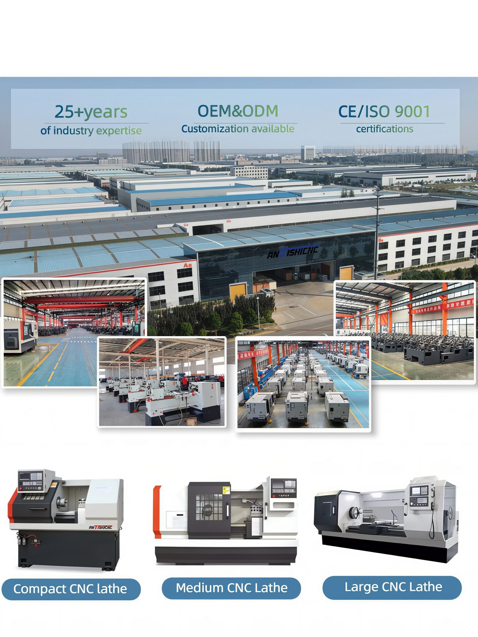
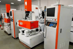
Those flatness, roundness, position and runout callouts are useless without a capable manufacturing machine-and at ANTISHICNC, we engineer-directly from our China-based factory-the ultra-precise grinders, lathes, and machining centers that achieve the specific tolerances on your drawings.
Explore Precision Grinding Equipment →
Ask Our Engineers a Tolerancing Question →
About This Guide
The GD&T reference guide was compiled from current industry standards including the ASME Y14.5-2018 and ISO 1101:2017 standards, current university engineering courses, research from NIST (the National Institute of Standards and Technology) related to Model-Based Definition and cross-referenced with machinists and metrologists. Any relevant mathematical reasoning for feature calculations, such as the mathematical explanation for the 57% increase in cylindrical-zone accuracy, is also shown so you can verify these details yourself. As a machine tool builder our interest is in practical function-clear, precise drawings lead to designs that can actually be built using our equipment.
References & Sources
- ASME Y14.5-2018, Dimensioning and tolerancing-American Society of Mechanical Engineers
- ISO 1101:2017, Geometrical Product Specifications (GPS)-Geometrical tolerancing-International Organization for Standardization
- Model-Based Manufacturing Capability Definition-U.S. National Institute of Standards and Technology (NIST)
- ENGR 170: GD&T-Position-Iowa State University College of Engineering
- geometric dimensioning & Tolerancing-Milwaukee School of Engineering
Related Articles
- Understanding the basics of lathe mills-how machining fundamentals are tied to blueprint callouts
- Choosing a CNC Lathe for Your next project-Matching machine specifications to tolerance needs
- Digital readouts (DROs) for lathes-repeating set-ups to hold stricter tolerances
- CNC Tool Grinding Machine- Precise geometry for tighter tolerance on your tools
- CNC VMC-Holding the required position tolerance for your holes.