




Updated September 2026
CNC lathe programming is the process of converting a drawing into a string of G-code and M-code blocks a turning center can execute, and for a beginner, the quickest way to master it’s one complete, annotated program rather than a long list of code definitions. This guide standardizes on Fanuc-style G-code, the de facto training and certification baseline, and walks through program structure, the G71/G70 roughing-and-finishing pair, G76 threading, G41/G42 tool nose compensation, a complete worked example, verification, and where conversational and AI-assisted programming now fit alongside hand-written code. Controller syntax differs more than most guides admit, LinuxCNC, for instance, uses entirely different G71 parameter letters (Q/X/Z/D/I/R) from the Fanuc P/Q/U/W/F structure used here, so always confirm your specific control’s manual before running any example on real hardware.
For the full G-code and M-code vocabulary this article assumes, see antishi’s companion G-Code & M-Code List reference; for machine anatomy and setup basics before programming, see Understanding CNC Lathe Basics for Beginners.
This guide works as a basic CNC lathe programming primer whether you are following a formal CNC lathe programming course, taking CNC lathe classes, or teaching yourself from real CNC lathe program examples online. Rather than isolated Fanuc CNC lathe programming examples or a CNC lathe programming software walkthrough, it builds toward one complete CNC lathe sample program you can adapt directly, whether you already know how to program a CNC lathe or are trying to learn CNC lathe programming for the first time. Later sections also cover where conversational CNC lathe interfaces fit in alongside hand-written code.
Quick Specs, What This Guide Covers
| Controller dialect | Fanuc-style G-code (2-block G71/G76 format) |
| Cycles covered | G71 (rough turn), G70 (finish), G76 (threading) |
| Compensation | G41 (left) / G42 (right) tool nose radius compensation |
| Example machine spindle | Up to 6,000 RPM, 37 kW (50 HP) — antishi 32-bit CNC lathe controller |
How a CNC Lathe Program Is Structured
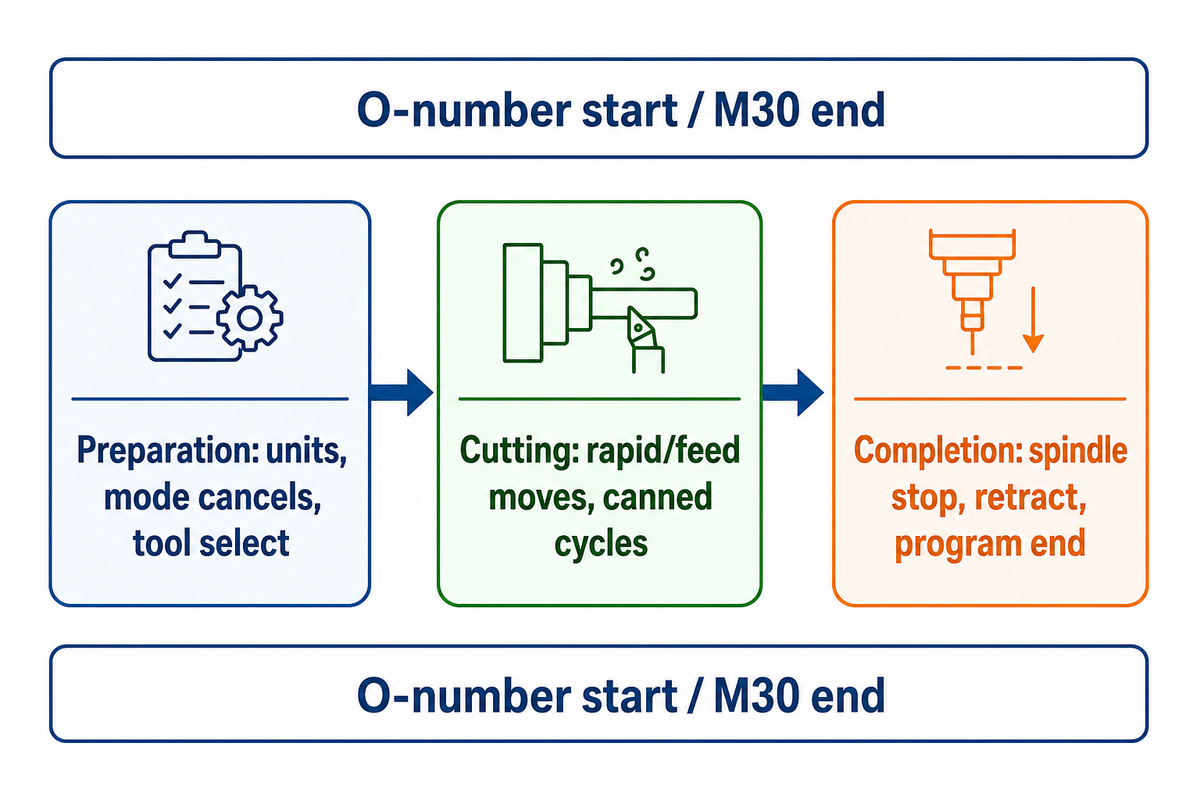
A CNC lathe program is a sequence of numbered blocks that executes in three distinct phases: preparation (setting units, canceling old modes, selecting a tool), cutting (rapid and feed moves, canned cycles), and completion (stopping the spindle, retracting, ending the program). Every program starts with an O-number identifier and ends with M30.
Unlike a mill, a lathe rotates the workpiece against a stationary tool, so its coordinate system and canned cycles are built around a rotating part rather than a moving cutter, a distinction that matters because some NEURONwriter-flagged terms in this guide (like “cnc machine” or “cnc mill”) come from content that mixes mill and lathe programming; this guide stays lathe-specific throughout.
O1234                    (program number)
G20 G40 G80 G99          (PREP: inches, cancel comp, cancel cycles, feed/rev)
T0101 G50 S3000          (PREP: tool 1/offset 1, clamp max spindle 3000 RPM)
G96 S400 M03             (CUTTING starts: constant surface speed, spindle on)
...                      (CUTTING: canned cycles and moves go here)
G00 X5.0 Z5.0 M09        (COMPLETION: retract, coolant off)
M05                      (COMPLETION: spindle stop)
M30                      (COMPLETION: program end, rewind)
This three-phase pattern, a preparation block, a cutting block, a completion block, is what a NIMS-aligned CNC curriculum (Ivy Tech Community College teaches lathe programming under this exact EIA/ISO G-code framework) and industry trade press both define as the skeleton every lathe program follows, regardless of part complexity.
CNC stands for computer numerical control: a computer executing programmed instructions rather than a person turning handwheels, following a fixed order of operations every time it runs. Every rapid motion (G00) and feed move traces a tool path along the X axis or Z axis, cutting into the part geometry to remove stock; canned cycles exist specifically to script these repetitive material-removal passes, like removing stock in a rough turn, without hand-coding each one. At its simplest, a CNC program is a set of instructions a machine tool follows exactly, which is why programming discipline matters even on a basic program for a simple part, and why getting speeds and feeds right the first time saves rework later.
Coordinate System and Essential Axis Codes
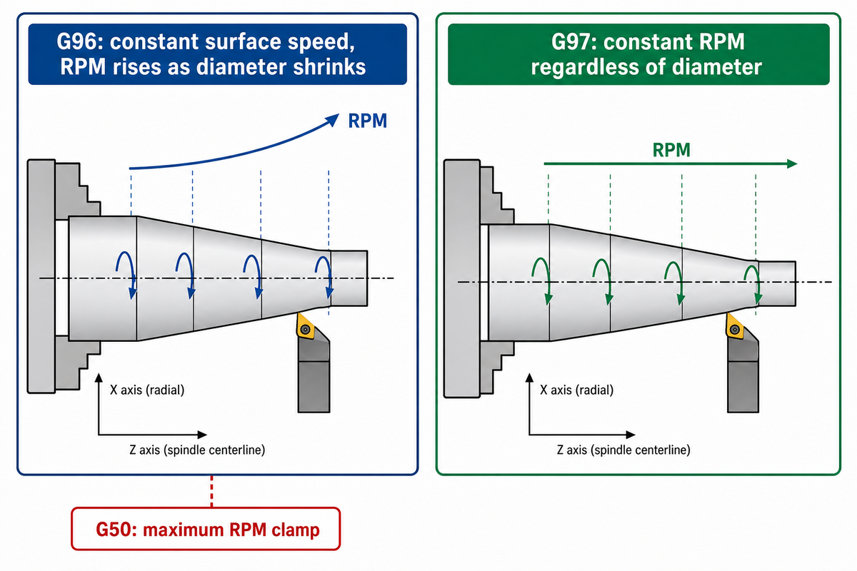
For any cut where diameter varies along the workpiece, a taper, a radius, a step-down, adopting G96 over G97 alters surface finish and tool life more than nearly any other setting on the machine. A lathe relies on two axes primarily: X (radial, diameter-mode by default on most Fanuc-style controls) and Z (along the spindle center line). G96 sustains constant surface speed (CSS) by continuously adjusting RPM as diameter changes; G97 sustains a fixed RPM regardless of diameter. G50 sets a maximum RPM clamp so G96 never lets the spindle overspeed on a small diameter.
What is the difference between G96 and G97?
G96 (constant surface speed) recalculates RPM continuously as the tool’s X position changes, so facing cuts across a large diameter and a small diameter both maintain the same actual cutting speed in surface feet per minute. G97 (constant RPM) holds one spindle speed no matter what diameter the tool is at.
A worked example: programming G96 S400 on a 4.0″ diameter workpiece targets 400 SFM, which the control converts to roughly 382 RPM (RPM ≈ (SFM × 3.82) / diameter); as the same tool cuts down to a 1.0″ diameter later in the same pass, the control automatically raises spindle speed to roughly 1,528 RPM to hold that same 400 SFM, which is exactly why G50 S3000 matters: without the clamp, a small-diameter finish pass under G96 could try to spin well past the spindle’s safe limit.
Lathe positions live on a Cartesian coordinate system, and only two axes move on a basic 2-axis lathe, X and Z; some advanced 3-axis or live-tooling machines add a C-axis for off-center milling work. Every move can be programmed as absolute or incremental: absolute states each position from the part’s work offset, typically set with G54, while incremental states each move relative to the last position. This guide uses absolute X-axis/Z-axis positioning throughout, the default on most Fanuc-style controls. The G/M-code letter-address format itself, including the axis and mode codes used here, traces back to the ISO 6983-1 numerical-control programming standard, which has defined this addressing scheme since 1980.
| Mode | Controls | Best for | Risk if misused |
|---|---|---|---|
| G96 | Surface speed (SFM), RPM auto-adjusts | Facing, tapers, varying-diameter turning | Overspeed on small diameter without a G50 clamp |
| G97 | Fixed RPM | Drilling, tapping, constant-diameter work | Wrong cutting speed at large or small diameters |
Turning Canned Cycles: G71 Roughing and G70 Finishing
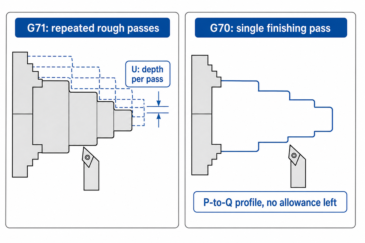
Two blocks of code handle nearly all bulk stock removal on a CNC lathe: G71 for repeated rough passes, G70 for a single finishing pass over the same profile. G71’s first line sets the roughing depth per pass (U) and retract distance (R); its second line points to a start sequence number (P) and end sequence number (Q) that bracket a finishing-profile subroutine, plus finish allowance in X (U) and Z (W) and a feed rate (F). G70 then re-runs that same P-to-Q block range, cutting exactly to the programmed profile with no allowance left.
G96 S400 M03             (constant surface speed, spindle on)
G00 X2.1 Z0.1 M08         (rapid to start point, coolant on)
G71 U0.1 R0.05             (rough: 0.1in depth/pass, 0.05in retract)
G71 P10 Q20 U0.02 W0.005 F0.012  (rough N10-N20, leave 0.02/0.005 for finish)
N10 G01 X0.8 F0.012
    Z-0.5
    X1.2 Z-0.75
    Z-1.5
N20 X2.0
G70 P10 Q20                (finish pass, same N10-N20 profile, no allowance)
Note: some controllers (e.g. Haas single-block variants, and non-Fanuc controls such as LinuxCNC) pack additional parameters, depth, X/Z rough allowance, spindle speed, tool number, into a single G71 block instead of splitting it across two lines. The two-line structure above is the classic Fanuc format and the one most training curricula and certification programs teach first, matching the University of Florida CNC lathe resources page‘s G71 stock-removal cycle parameter set.
Threading with G76: A Lathe-Specific Cycle
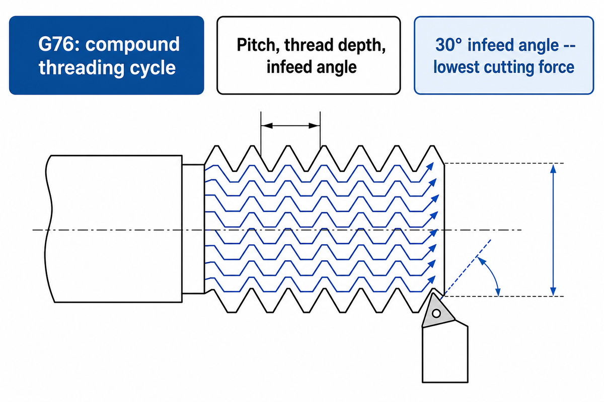
G76 does in one compound cycle what dozens of hand-coded G01 passes would take to accomplish, but only on a lathe. On CNC lathes, G76 programs a compound external or internal threading cycle using pitch, thread depth, and infeed angle in a single two-block pair, rather than hand-coding every individual threading pass. Before the parameter breakdown below, one caveat worth stating plainly: on some Fanuc-compatible milling controllers, G76 is assigned to a completely different canned cycle (fine boring), not threading, canned-cycle code numbers are not universal across mill and lathe contexts, so always confirm which machine type a reference table describes before copying a code number.
G76 P011060 Q100 R0.05    (1 finish pass, 0.06in chamfer, 60° infeed angle, 0.05in finish allowance)
G76 X1.773 Z-1.0 P1147 Q400 F0.05  (minor dia 1.773in, thread height 0.1147in,
                                     first cut 0.004in, feed = 0.05in pitch)
The infeed angle (the aa pair packed into the first line’s P value, commonly 29°, 30°, 55°, 60°, or 0° for straight/radial infeed) is not just a formality: a CNC external-threading study on AISI 1050 steel, testing 0°, 14.5°, 15°, 27.5°, and 30° infeed angles at a constant 100 m/min cutting speed, found 30° to be the optimum infeed angle in terms of cutting forces, meaning infeed-angle choice measurably affects tool load, not just thread geometry. G76 threading pairs naturally with a dedicated internal link for readers coming from manual threading methods: see antishi’s guide to threading on a lathe for how G76 compares to manual single-point threading.
Tool Offsets and Nose Radius Compensation
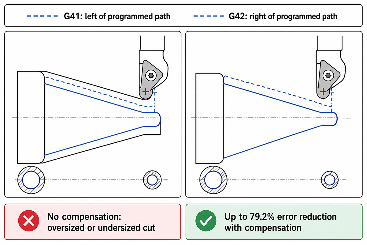
Tool nose radius compensation, called with G41 (left of the programmed path) or G42 (right of the programmed path), corrects for the small radius ground onto every turning insert, skip it on a taper or radius and the part comes out the wrong size relative to the programmed profile, sometimes by a measurable margin. A peer-reviewed CNC turning study measured a nominal 0.4mm insert radius, worn down by normal tool wear to an average 0.3743mm in service; applying compensation reduced average machining error across the tested workpieces by up to 79.2% compared to running the same program uncompensated. Tool changes and tool selection matter just as much as compensation math: indexing the tool turret to the wrong station, or entering a geometry offset against the wrong tool number, silently corrupts every subsequent cut with that tool.
What happens if you skip tool nose radius compensation?
Without G41/G42 active, the control machines to the tool’s theoretical center point rather than the actual cutting edge, so straight cuts along a single axis come out correct while any taper, radius, or contour comes out oversized or undersized by roughly the insert’s radius.
Geometry and wear offsets still need to be entered separately at the control (measured off a test cut or touch-off probe, keyed into the offset table under the tool’s number) before compensation can apply correctly, compensation corrects the toolpath shape, offsets correct the toolpath position.
- Cutting any taper, radius, or contour
- Chamfers and blended profiles
- Any G70 finishing pass over a G71-roughed profile
- Pure straight-line cuts along one axis only
- Tight-clearance boring with no room for the tool’s exit move
- Programs meant to move between machines with mismatched offset tables
“Some experienced programmers historically avoided G41/G42 because a job that moved between machines with different tool libraries could throw off nose-radius compensation in ways a manually adjusted toolpath would not.”
— a common practitioner caution reported in machinist forum discussions
A Complete Worked Example: From Blank to Finished Part
If everything above still feels abstract, here’s one complete program, facing, rough and finish turning with compensation, drilling, and threading, annotated line by line on a 2″ round bar down to a threaded step. If you searched for CNC lathe programming FANUC or CNC lathe programming with example specifically, this is that walkthrough: a complete program, not just isolated snippets, stringing together the same G71/G70/G41/G42 canned-cycle syntax documented on the University of Florida CNC lathe resources page into one program.
O2001 (2IN BAR, FACE-TURN-DRILL-THREAD)
G20 G40 G80 G99            (inch mode, cancel comp/cycles, feed/rev)
T0101 G50 S3000            (turret tool 1 offset 1, clamp spindle at 3000 RPM)
G96 S400 M03 M08           (constant surface speed 400 SFM, spindle on, coolant on)
G00 X2.1 Z0.1              (rapid to facing start point)
G01 Z0 F0.012               (feed to face, touch part)
X-0.05 F0.008               (face across center)
G00 X2.1 Z0.1               (retract, reposition for OD roughing)
G71 U0.1 R0.05              (rough turn: 0.1in depth/pass, 0.05in retract)
G71 P10 Q20 U0.02 W0.005 F0.012  (rough N10-N20, leave finish stock)
N10 G01 X0.8 F0.012
    Z-0.5
    X1.2 Z-0.75
    Z-1.5
N20 X2.0
G41 G70 P10 Q20              (finish pass, nose compensation LEFT active)
G40                          (cancel compensation)
G00 X5.0 Z5.0 M09           (retract clear, coolant off)
T0202 M03 S1200 M08          (index to drill, drill speed, coolant on)
G00 X0 Z0.1
G74 R0.05                    (peck drilling retract)
G74 Z-0.75 Q0.15 F0.005      (peck drill to 0.75in deep, 0.15in pecks)
G00 X5.0 Z5.0 M09
T0303 M03 S600 M08           (index to threading tool)
G00 X1.85 Z0.1
G76 P011060 Q100 R0.05       (1 finish pass, 0.06in chamfer, 60° angle)
G76 X1.773 Z-1.0 P1147 Q400 F0.05  (thread to 1.773in minor dia, 0.05in pitch)
G00 X5.0 Z5.0 M09
M05                           (spindle stop)
M30                           (program end)
Every line of code in this program reuses cycles already explained above, the facing pass, the G71/G70 roughing-and-finishing pair with G41 nose compensation on the finish pass, a peck-drilling cycle, and the G76 threading cycle, so this program is meant as a template you can adapt to your own drawing, not a one-off example to memorize.
Canned-Cycle Parameter Reference
| Parameter | Used In | Meaning | Example Value |
|---|---|---|---|
| U (1st line) | G71 | Depth of cut per pass | 0.1in |
| R (1st line) | G71 | Retract distance | 0.05in |
| P | G71 / G70 | Start sequence number | N10 |
| Q | G71 / G70 | End sequence number | N20 |
| U (2nd line) | G71 | X finish allowance | 0.02in |
| W | G71 | Z finish allowance | 0.005in |
| F | G71 / G70 | Feed rate | 0.012in/rev |
| P (1st line) | G76 | Finish passes / chamfer / infeed angle (packed) | 011060 |
| Q (1st line) | G76 | Minimum depth per pass | 100 (0.01in) |
| R (1st line) | G76 | Finish allowance | 0.05in |
| X / Z (2nd line) | G76 | Thread end point | X1.773 Z-1.0 |
| P (2nd line) | G76 | Thread height (radius value) | 0.1147in |
The 14-Code Quick Reference Map
| Code | Type | What It Does |
|---|---|---|
| G20 | Setup | Inch units |
| G40 | Setup | Cancel tool nose compensation |
| G50 | Setup | Clamp maximum spindle RPM |
| G96 | Motion mode | Constant surface speed |
| G97 | Motion mode | Constant RPM |
| G71 | Canned cycle | Rough turning |
| G70 | Canned cycle | Finish turning |
| G76 | Canned cycle | Threading |
| G74 | Canned cycle | Peck drilling |
| G41 / G42 | Compensation | Tool nose radius, left / right |
| M03 | Spindle | Spindle on, clockwise |
| M05 | Spindle | Spindle stop |
| M08 / M09 | Coolant | Coolant on / off |
| M30 | Program | Program end, rewind |
A full lathe program is combinatorial, not encyclopedic: master three phases, two roughing/finishing cycles, one threading cycle, and G41/G42 compensation, and you can read or write nearly any beginner-to-intermediate lathe program from scratch.
Verify Before You Cut: Simulation and Dry Run
Before a single chip is cut, a documented verification habit is what separates a program that runs clean from one that crashes a tool or scraps a part. Bypassing a machine’s safety interlocks or guards to save time is a real and sometimes fatal risk, not a hypothetical one: OSHA’s investigation into a March 2016 fatality at Carlson Tool & Manufacturing Corp. of Cedarburg, Wisconsin found the lathe’s interlocked guard door had been left open, exposing the operator to the machine’s rotating spindle, and cited the employer for a willful safety violation with a $124,709 penalty. Verification is the alternative to that shortcut.
- Graph or backplot the program — most controls and CAM packages can trace the toolpath on screen before any motion happens, catching gross coordinate or cycle errors first.
- Dry-run with the door closed — run the program at rapid/no-cut to confirm every move clears the chuck, tailstock, and tooling, keeping a hand near the feed-hold or override at all times.
- Single-block the first cut — step through the first actual cutting pass one block at a time, checking coordinates and offsets against the drawing before letting the program run continuously.
Many controls also support MDI (Manual Data Input) for quick single-block tests, for example keying in G97 S500 M03 to confirm spindle behavior without loading a full program, which lets a skilled operator sanity-check an offset before committing the actual machine to a full cutting pass.
A 2024 patent for machining-simulation devices on numerically controlled lathes reflects the same direction the industry is moving: setting the program origin from a simulation coordinate system to reduce or eliminate physical touch-off measurement, cutting setup time without cutting the verification step itself.
Manual Coding vs. Conversational and AI-Assisted Programming
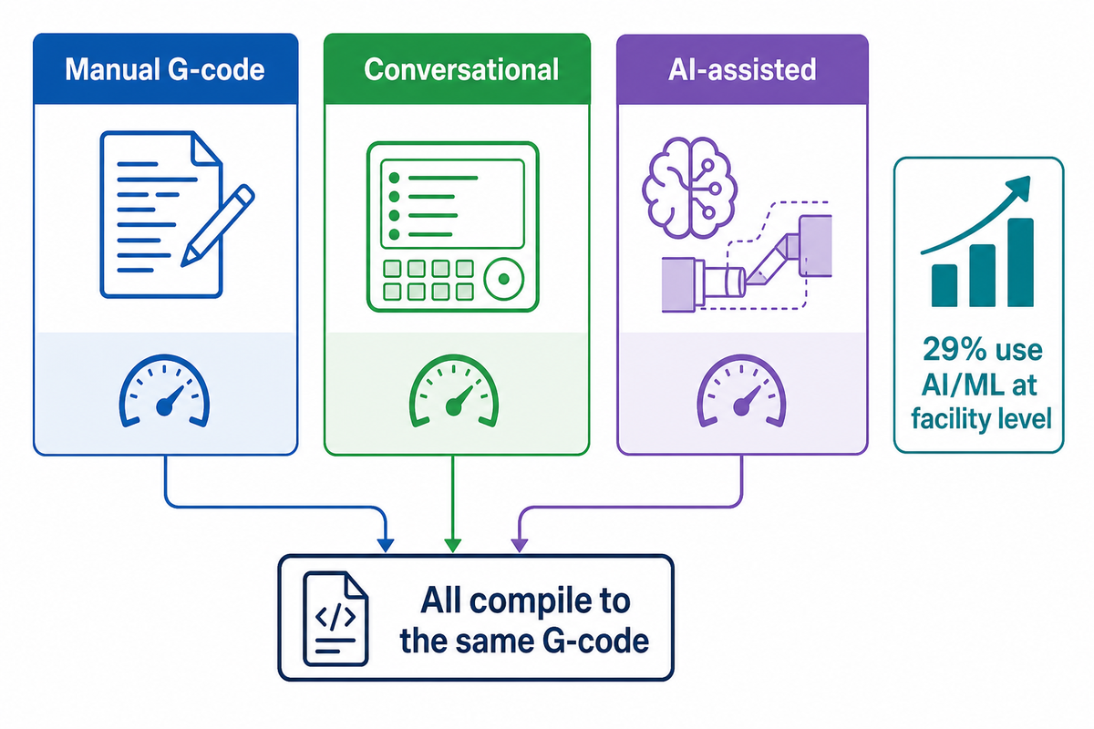
Manual G-code, conversational (menu-driven) programming, and AI-assisted toolpath generation now solve the same problem three different ways, and every one of them still has to pass the graph/dry-run/single-block checks from the previous section before it touches real metal; modern controllers, including antishi’s own 32-bit CNC lathe controller, increasingly support more than one on a single machine. Before comparing the three methods directly, it helps to know how stable the underlying code format actually is: the G-code format has a long, comparatively stable lineage, the EIA’s RS-274 standard was finalized as RS-274-D in 1979, and it was later standardized internationally as ISO 6983-1, first published in 1982 and revised once since, in 2009, with no new revision announced for 2024 or 2025. So the code format itself changes rarely; what is actually shifting year to year is generation method, not the underlying syntax. CAM (computer-aided manufacturing) programming software such as Mastercam, usually reading a CAD (computer-aided design) file as its starting point, remains the standard across CNC machinery generally, not just lathes but CNC routers, mills, and multi-axis turning centers too, for producing complex parts and complex shapes at volume, whether the goal is a one-off prototype or a production run to produce parts by the thousand; G-code stays the programming language used underneath every one of them, the same way most computer programming eventually compiles down to machine instructions.
| Method | What it is | Fastest for | What you still need to know |
|---|---|---|---|
| Manual G-code | Hand-written blocks, as in this guide | Custom canned-cycle logic, editing at the control | Full syntax and cycle parameters |
| Conversational | Menu/wizard-driven prompts that generate G-code — available on Fanuc, Siemens, Haas, Mazak, and other major controls | Simple parts, fast shop-floor programming | How to read the generated code to verify it |
| AI-assisted | Natural-language or model-generated toolpaths from CAD input | First-pass drafts from a part file | Verification before cutting — output still needs the checks from the section above |
The scale of this shift is no longer speculative: in Deloitte’s 2025 Smart Manufacturing and Operations Survey, 29% of large U.S. manufacturers reported using AI or machine learning at the facility level, and 24% had deployed generative AI at that scale, figures reported by trade press covering the same shift toward automation in program generation. Academic research on self-correcting, feedback-driven G-code generation is active as of 2025, which is a substantively different claim than “can ChatGPT write G-code” — the tooling has moved past novelty demonstrations. None of that removes the need to read and verify G-code: conversational and AI-generated programs both compile down to the same G-code this guide covers, and every verification habit from the previous section still applies to code you did not type yourself. If your control supports conversational programming and the part is simple, conversational is usually faster; if you need portability across machines or CAM interchange, or the part needs custom canned-cycle logic, hand G-code remains the more reliable choice. For a deeper comparison of lathe categories and CNC turning centers generally, see antishi’s CNC Lathe vs. CNC Turning Center guide.
Frequently Asked Questions
Q: Is CNC programming hard to learn?
The core G-code concepts are learnable in weeks, but real proficiency takes months of hands-on practice, reading offsets correctly, catching mistakes, and building the judgment that good training pairs with supervised machine time.
Q: How do I program a CNC lathe?
Start with the three-phase structure, then layer in canned cycles for roughing, finishing, and threading; the complete worked example in this guide walks through that exact sequence on one real part.
Q: Can ChatGPT make a CNC program?
Large language models can draft G-code from a description, but the output still needs the same graph, dry-run, and single-block verification any hand-written program does before it touches real metal.
Q: How to program a CNC turning machine?
The process is identical to lathe programming: “turning machine” and “lathe” describe the same class of equipment, so every canned cycle and verification step in this guide applies directly.
Q: What is the highest salary for a CNC programmer?
U.S. Bureau of Labor Statistics data puts the top 10% of CNC tool programmers at $94,880 a year as of May 2023, with a national median of $63,440 across 28,030 workers.
Q: Where can I learn CNC programming for free?
Community college open curricula, controller manufacturers’ own free documentation, and machinist forums like Practical Machinist are the three main free starting points most working programmers actually used.
About This Analysis
This guide standardizes on Fanuc-style G-code because it’s the dialect most CNC certification curricula and the majority of search demand for this topic (including “Fanuc CNC Lathe programming Examples”) assume, and antishi’s own 32-bit CNC lathe controllers support both G-code and Conversational programming, referenced directly in the section comparing programming methods above. Reviewed by the SHANGHAI ANTS Machine Equipment technical team.
References & Sources
- NIMS CNC Lathe and Milling Programming Ivy Tech Community College
- CNC Lathe Training Resources University of Florida
- Occupational Employment and Wage Statistics, CNC Tool Programmers U.S. Bureau of Labor Statistics, May 2023
- ISO 6983-1 International Organization for Standardization
- Modelling of the Effect of Different Infeed Angles and Cutting Areas on the Cutting Forces in External Threading Gazi University (peer-reviewed)
- Tool nose radius wear and compensation accuracy study PubMed Central (peer-reviewed)
- WO2024095367A1, Machining simulation device, numerically controlled lathe Google Patents
- OSHA investigation of lathe operator’s fatal injuries U.S. Department of Labor
- Handing Over the Keys: State of the Machine Shop CNC Programming American Machinist
- Programming a CNC Lathe Cutting Tool Engineering
Related Articles
- CNC Lathe Machine antishi’s full CNC lathe product line, including the 32-bit controller referenced throughout this guide
- G-Code & M-Code List: The Complete CNC Programming Reference full code glossary for both milling and turning
- Advanced Techniques for CNC Lathe Operations the natural next read after this beginner tutorial