





Updated October 2026
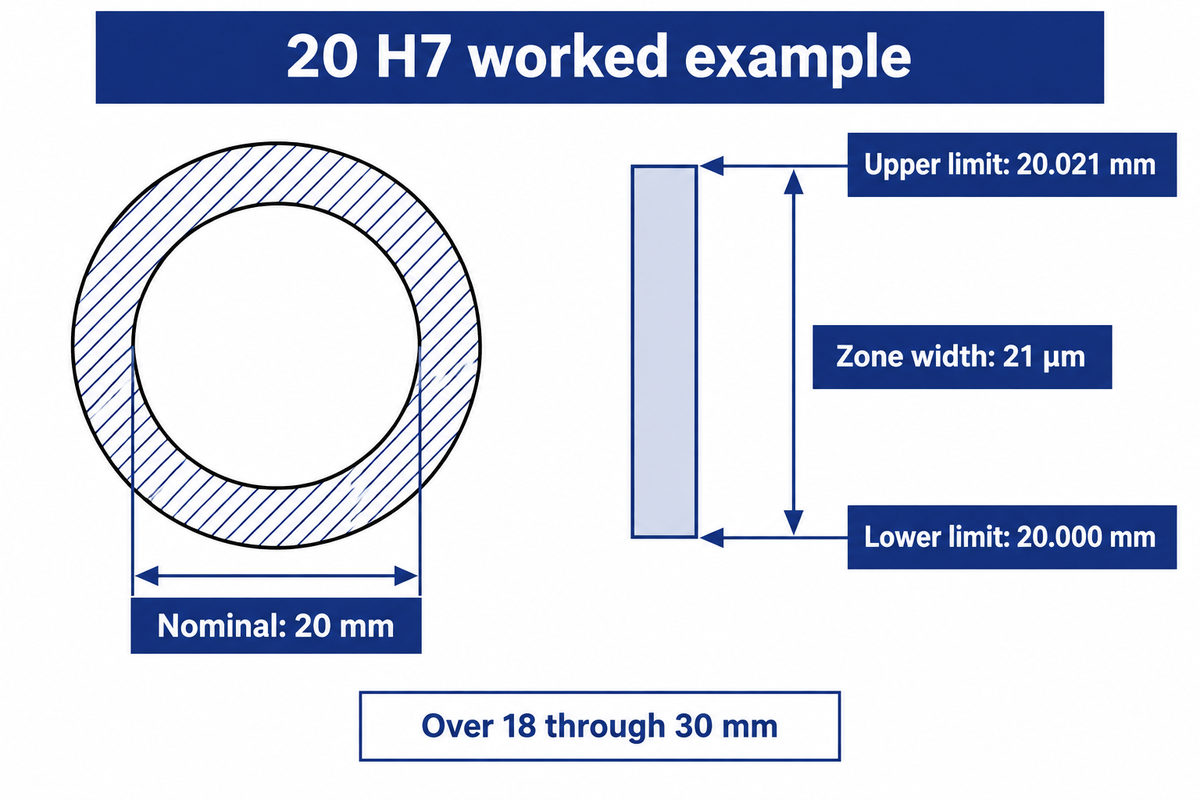
A hole tolerance chart determines permitted size limits. For a 20 mm H7 hole, those limits are 20.000–20.021 mm. When choosing an allowed diameter interval, connect the size requirement of one part to that of the other (mating) part, via the machining process and inspection method.
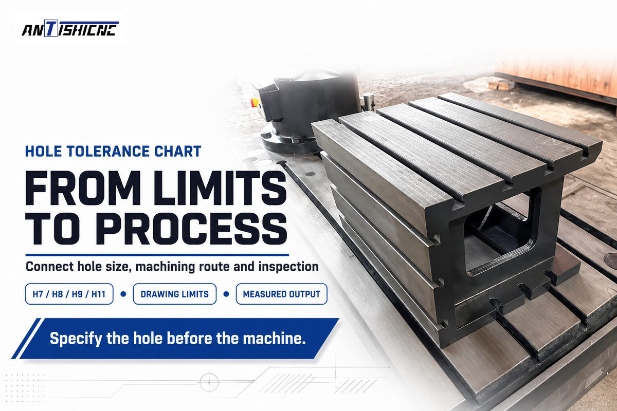
Machine buyers comparing radial drilling machine configurations also need to distinguish a correctly sized hole from a correctly located one. The reference chart below leads into a Hole Limits-to-Process Map and a completed 3-Limit Hole Passport, so manufacturing and purchasing can work from the same drawing.
Hole tolerance chart: H7, H8, H9 and H11 limits
H7, H8, H9 and H11 holes have zero lower deviation in the H system; their upper limit depends on nominal size and grade. Add the deviation to the base diameter. Read “over” as exclusive and “through” as inclusive: exactly 6 mm belongs to the first row.
| Basic diameter, mm | H7 upper | H8 upper | H9 upper | H11 upper |
|---|---|---|---|---|
| Over 3 through 6 | +12 | +18 | +30 | +75 |
| Over 6 through 10 | +15 | +22 | +36 | +90 |
| Over 10 through 18 | +18 | +27 | +43 | +110 |
| Over 18 through 30 | +21 | +33 | +52 | +130 |
| Over 30 through 50 | +25 | +39 | +62 | +160 |
Source: RoyMech hole tolerance tables. The compact chart covers only the stated metric sizes and H classes. Other hole zones require their own upper and lower limit deviations.
Example: a purchasing engineer receives a drawing marked 20 H7. Since 20 mm falls over 18 through 30 mm, the permitted increase is 21 µm. Divide by 1,000 to convert it to 0.021 mm. The finished hole may therefore measure from 20.000 mm to 20.021 mm under the drawing’s measurement conditions. Writing ±0.021 mm would create a different, wider zone and allow an undersize hole.
At the 6 mm boundary, H7 allows 6.000–6.012 mm; just above 6 mm, the next size band has a 15 µm width. Following that interval rule prevents a supplier from assigning the wrong allowance when the drawing dimension happens to be on a chart endpoint.
Read ISO 286 hole and shaft designations
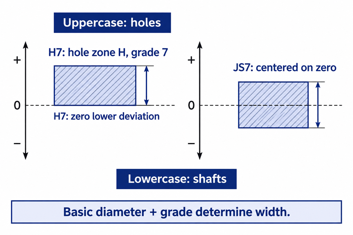
A designation combines a size, a letter Defining Zone Position, and a number Defining tolerance grade. Uppercase letters identify holes; lowercase letters identify shafts. The ISO system of limits and fits uses these parts together, so neither the letter nor the grade, in and of themselves, provides a complete dimension.
ISO 286-1:2010 defines the code system and the concepts behind hole basis and shaft basis fits. In the hole-basis system, the H hole starts on the zero line, and the shaft tolerance zone is then selected to provide the required assembly relationship.
How do I interpret notations such as H7, G7 and JS7?
Read H7 as an H position hole zone with grade 7 width, G7 as a grade 7 zone with different position, and JS7 as a zone centered around zero line. H7 has zero lower deviation; the other letters change where the permitted sizes sit. The basic diameter is used to determine width.
For example, a grade number isn’t a fixed micrometre value across all diameters. An H7 zone is 12 µm wide in the over 3 through 6 mm band and 21 µm wide in the over 18 through 30 mm band. G7 and JS7 must be read from the matching columns, rather than treated as alternative spellings of H7.
The location of a tolerance zone relative to the basic size is determined by the fundamental deviations in Mechanical engineering drawings. The resulting tolerance range is used in engineering calculations with the limits of the mating part.
The tolerance calculator can accelerate the lookup. Its inputs still need the correct shaft or hole, nominal size and governing standard. Keep the original code next to the calculated limits so a copied spreadsheet value can still be identified.
Drilled, reamed or bored holes: choose the process
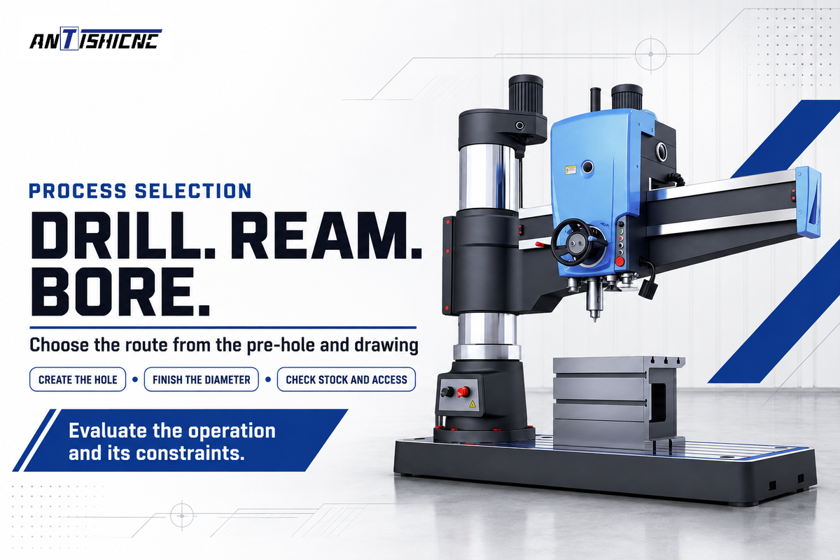
Choosing the drilling operation will produce the hole. Reaming will finish a suitably prepared hole. Boring is used for controlled enlargement or corrections of the hole axis. Diameter, depth, stock condition and workholding decide the route. The hole grade describes the required size zone; the tools describe the operation.
The Harvard shop terminology guide distinguishes these three operations. John Miller’s boring-versus-reaming discussion explains why an imperfect pre-hole can favor boring: A reamer tends to follow the pre-existing hole, while suitable boring tooling can create a different cutting path.
- Finish an adequately prepared hole.
- Use a tool sized for the required diameter.
- Check pre-hole alignment and stock allowance.
- Enlarge and finish an existing hole.
- Adjust a suitable boring tool for diameter.
- Check available stock and tool access for axis correction.
Use Hole Limits-to-Process map to determine the next operation based on the actual problem, rather than purchasing a tighter tool because of a hole being misplaced. Bores on rotational parts can also be planned within a CNC turning process, with the same drawing controls carried into inspection.
| Observed requirement | Route to evaluate | Reason | Trial output |
|---|---|---|---|
| No existing hole | Drill | Create access and initial geometry | Size, depth and location |
| Sound pre-hole; repeated diameter | Ream | Finish a prepared diameter | Size through the run |
| Pre-hole axis displaced | Bore with sufficient stock | Establish a controlled cutting path | Position relative to datums |
| Many different diameters | Adjustable boring tooling | Reduce dependence on dedicated sizes | Setup and diameter records |
| Long repeated batches | Compare reaming and boring | Balance cutting time against tool cost | Accepted parts and cycle time |
| Blind hole | Check tool end geometry | Bottom clearance and chip removal constrain access | Usable finished depth |
| Deep or interrupted hole | Evaluate support and coolant route | Deflection and chips alter the cut | Size along depth |
| Thin wall or heavy restraint | Review fixture before final sizing | Release can change the measured condition | Clamped and released observations |
| One-hit production target | Evaluate the specified drill system | Some tooling avoids a separate finish pass | Drawing conformance after drilling |
Seco’s article on holemaking options describes solid-carbide drilling applications within IT8 that can eliminate the need for a secondary finishing operation. That’s an exception to the drilling and reaming ladder. Tool design, coolant and fixture rigidity are within the process decisions.
Example: a buyer needs a 20 mm H7 through-hole in a 20 mm-thick steel plate. The pre-hole is displaced from the datum position. Simply installing a 20 mm reamer targets diameter while leaving the axis problem unresolved. The manufacturing engineer will check whether enough material remains around the required axis. If it does, a boring trial can address position and final size; if it does not, the blank or upstream operation needs correction before finishing.
Clearance, transition and interference fits
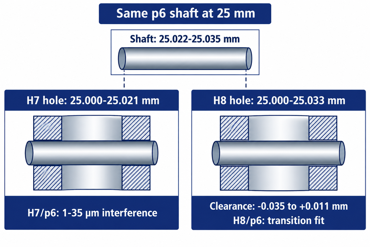
Determine fit type, from four limits: the smallest and largest allowed hole and shaft diameters. Minimum clearance equals the smallest hole minus the largest shaft. Maximum clearance equals the largest hole minus the smallest shaft. Positive results indicate clearance; negative results indicate interference; a range crossing zero permits either outcome.
For shaft and hole pairs intended to slide, the fit of the assembly is important because the tightest permitted combination still must satisfy the assembly’s requirements. Interference fits require evaluation of the opposite relationship, together with material, wall thickness, surface condition and assembly method.
Example: at 25 mm, the published p6 shaft limits are 25.022–25.035 mm. An H7 hole is 25.000–25.021 mm. Minimum clearance is 25.000 − 25.035 = −0.035 mm; maximum clearance is 25.021 − 25.022 = −0.001 mm. The pair therefore has 1–35 µm interference. Retain that shaft and change the hole to H8, 25.000–25.033 mm: clearance becomes −0.035 to +0.011 mm. The zones now overlap, producing a transition fit rather than guaranteed interference.
Both the hole limits and shaft limits are required for that determination. Changing H7 to H8 doesn’t preserve fit type in all pairs.
How do I determine the hole tolerance for an m6 shaft?
Select the hole class from the required assembly fit and the shaft’s actual m6 limits at the specified basic size. The shaft code alone doesn’t prescribe one matching hole. Calculate the two worst-case differences, then assess the resulting clearance or interference with the component’s required assembly behavior.
A locating pin, removable bushing and retained sleeve need different assembly behaviour even when they share a nominal diameter. Start with that assembly behavior, then compare candidate ISO fits using their hole and shaft limits. A calculator’s “transition” label describes possible dimensional overlap. It does not stipulate the required assembly behavior, and it does not select the required assembly force and retention method for the component.
Specify hole size, form and position on the drawing
Explicitly state size and form, and indicate datum-relative position, to allow the manufacturing and inspection of the feature. Sometimes the constraints of the applicable drawing rules cause the requirements to interact. In ASME’s official training, Rule #1 is cited as an example where size determines form. As such, treating all diameter and form requirements as independent requirements would be incorrect.
The ASME geometric dimensioning course covers both that relationship and datum reference frames. A diameter callout alone cannot establish the location of hole relative to the rest of the assembly.
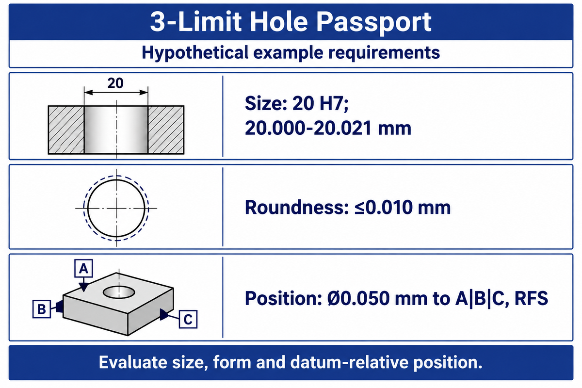
Example: The 3-Limit Hole Passport shows a drawing for a hypothetical hole of 20 mm. Its roundness and position are considered design inputs. The completed records document the acceptance requirements prior to a supplier making a choice of tooling or gauge.
| Characteristic | Recorded requirement | Evaluation task | Release condition |
|---|---|---|---|
| Size | 20 H7; 20.000–20.021 mm | Measure diameter at agreed depths and directions | Specified temperature and restraint |
| Form | Roundness ≤0.010 mm | Evaluate the specified form characteristic | After final machining and cleaning |
| Location | Position Ø0.050 mm to A|B|C, RFS | Establish datums and evaluate position | Drawing’s datum and material-condition rules |
A plug gauge can provide an answer to its assigned functional size question. Evaluating roundness and position requires additional consideration. All three requirements need to be addressed in the machine trial to avoid acceptance of an in-size hole that doesn’t satisfy the required mating geometry.
Measurement: verify the limits on the real part
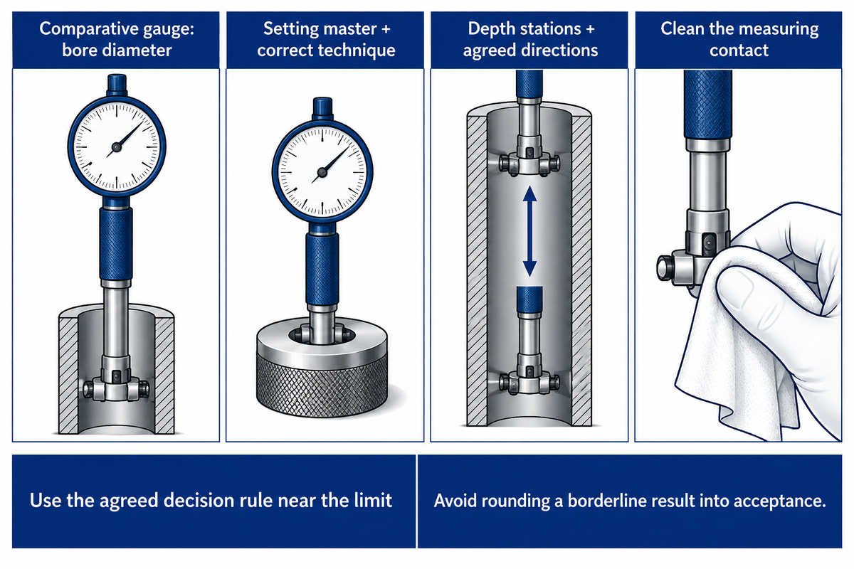
For different inspection questions, different methods and instruments are utilized based upon the feature and the tolerance zone. For example, for a bore diameter, a comparative gauge may be used; air gauging may be used for evaluating bore size; a CMM may be utilized to evaluate measured points against a defined feature.
George Schuetz of Mahr, in the article The Right Gage for Measuring Small Bores, outlines some of the factors that are to be considered for small bore measurements. An example is nominal instrument resolution. By itself, it doesn’t establish measurement uncertainty. For comparative gauges, correct master and setting technique are a prerequisite for a correct measurement.
For a 20 H7 hole, record readings along the bore and in the agreed directions, rather than relying on one convenient entrance measurement. The plan must account for depth stations, condition of the part, master, calibration, and if the part was measured under restraint. Burrs and trapped chips can change the contact before the instrument measures the intended surface.
ISO 14253-1:2017 addresses decisions about conformity with geometrical specifications when measurement uncertainty matters. Use the agreed decision rule near the limit and avoid inventing a universal gauge ratio or rounding a borderline result into acceptance.
The method used to define the hole as a datum also is important. A NIST study of constrained least-squares datum definitions discusses instability of some hourglass, barrel and tapered cylindrical features. The focus of that study is on methods for establishing datum. The inspection plan must state which association method is used instead of switching methods between suppliers.
A 20.000–20.021 mm hole has a 21 µm size zone, yet its acceptance still rests on a defined measurement process. Naming the master, measuring positions, and a decision rule, gives the supplier and incoming inspection the same task, so disagreements in acceptance can be traced to a condition rather than settled by adding extra decimal places.
Why holes drift: stock, heat and workholding
Check the observed hole error before changing the machine offset. Potential causes of hole errors could include unclamping the part, changing the tool, a change in coolant, part temperature, or tool wear. Keep all of these factors, the hole, and the measurement record to help explain the cause of the errors and to provide a basis for correction.
Troubleshooting runout, misalignment, cutting conditions, and stock removal is in Super Tool’s reaming troubleshooting guide. Its instruction that a reamer follows the drilled hole explains why diameter correction and location correction should be considered together.
In a Practical Machinist discussion, contributors mentioned the importance of working with actual material and thickness as well as checking runout and coolant. Advice on stock removal varies between different applications. The important lesson is to retain those conditions in the trial record instead of incorporating one of the contributors’ allowances as a default.
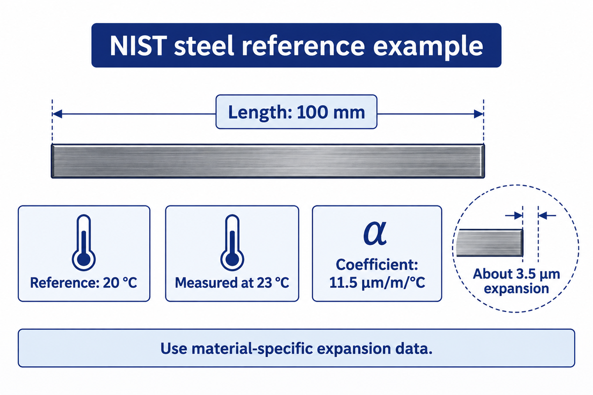
Example: incoming inspection measures a steel reference at 23 °C while the drawing dimensions refer to 20 °C. NIST’s dimensional metrology FAQ gives a 100 mm steel gauge-block example: with an expansion coefficient of 11.5 µm/m/°C, the 3 °C difference produces about 3.5 µm expansion. The reference temperature and material-specific correction therefore belong in the investigation before an operator compensates the cutting tool. The same calculation can’t be assigned to a different material without its expansion data.
For an example on reference-temperature, see the NIST dimensional metrology FAQ. For broader controls, the tight tolerance machining guide relates temperature, workholding and measurement to a particular part.
Compare machine suppliers with a hole trial
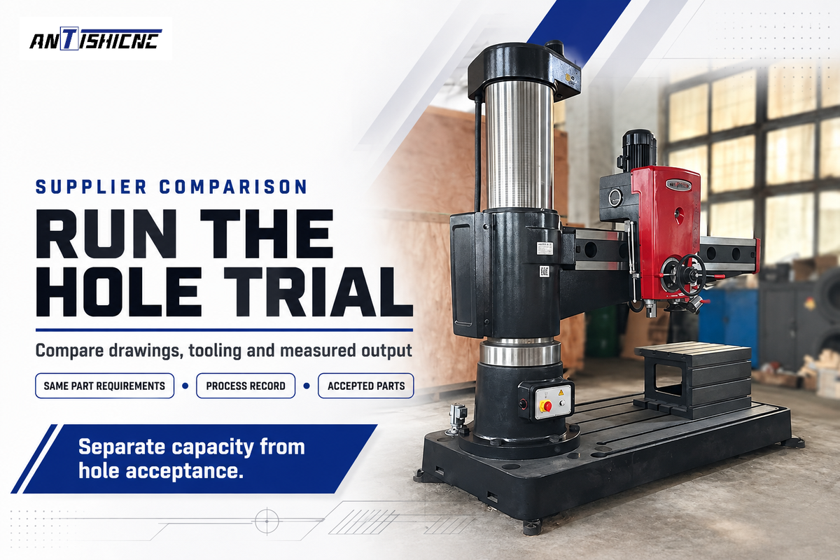
Consider suppliers on the same drawings, materials, and complete machining. The sample record should provide information on tooling and fixtures, cutting conditions, measurement and part inspection, and the order of parts. Separate the machine’s physical capacity from the process output needed for the order. Only then compare quotations for similar scope and content.
ANTISHICNC’s radial drilling machine range lists the Z3050×16-1 with a 50 mm maximum drilling diameter, 315 mm spindle travel and 4 kW main motor. The separate Z3063x20 card lists 63 mm, 400 mm and 5.5 kW respectively. These ratings help screen the work envelope and drilling task; the finished-hole trial addresses the drawing.
The distinction becomes costly when one quotation includes tooling and inspection, while the other only includes the machine. For multi-operation production, the automotive machining guide illustrates how process routes correlate to accepted-part cost. Record cycle time, setup time, tool consumption and inspection effort against accepted parts. If reaming shortens cutting time but needs extra pre-hole control, that upstream effort belongs in the comparison as well.
“we cannot begin to talk about process capability until we have demonstrated stability in our process.”
A short demonstration can support a buying decision, and need not represent a long-term capability study. Production and Quality should agree on which question the demonstration answers. Tooling adjustments should be recorded. For example, a toolmaker’s adjustment in size during the run should be recorded. This shouldn’t disappear into the final list of accepted diameters.
Industry outlook: specify the size standard in your enquiry
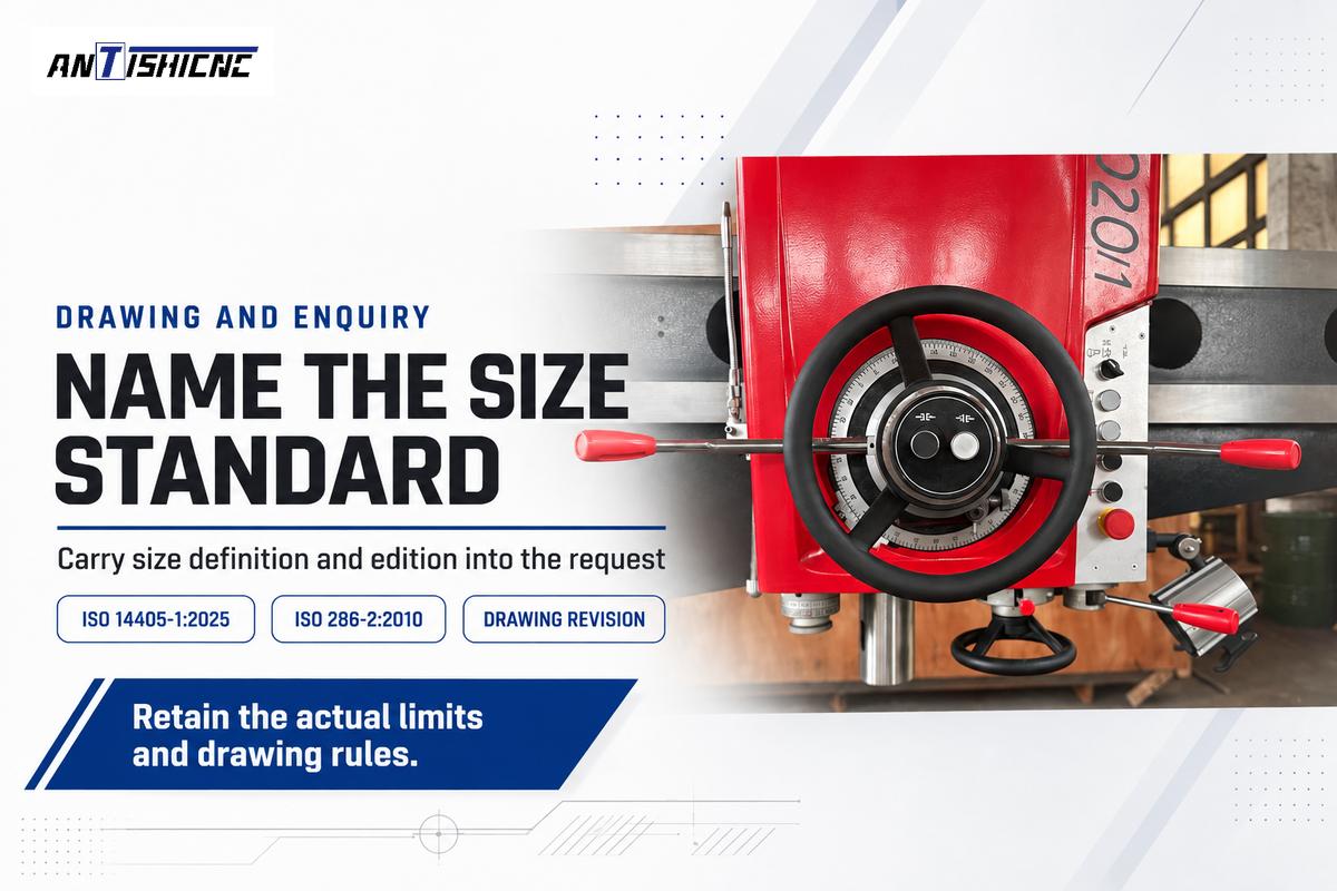
ISO 14405-1:2025, published as edition 3 in August 2025, addresses linear-size specification operators. That makes the drawing’s size definition and governing edition useful enquiry inputs. Keep them with the nominal dimension and limit values, especially when a customer and supplier use different drawing conventions.
The ISO 14405-1:2025 publication concerns how linear sizes are specified. Meanwhile, ISO 286-2:2010 remains the current edition following confirmation in 2026. The new linear-size edition is not a reason to replace the H7 numbers with an assumed new allowance.
In view of the hypothetical 20 mm hole already included in the passport, the following enquiry inputs keep the machining and acceptance task aligned. Complete the relevant fields in a controlled quotation request, replacing the example design inputs with the actual drawing.
RFQ checklist — example inputs for the 20 mm hole:
| Parameter | Recommended range | Why it matters | How to verify |
|---|---|---|---|
| Finished size | 20.000–20.021 mm, H7 | Defines the size acceptance zone | Drawing revision and agreed size method |
| Through depth | 20 mm plate thickness | Constrains tool access and chips | Part model and trial section |
| Roundness | ≤0.010 mm | Defines the form requirement | Specified form evaluation |
| Position | Ø0.050 mm to A|B|C, RFS | Connects hole and assembly datums | Approved datum setup and report |
| Reference temperature | 20 °C | Gives dimensional results a common reference | Temperature record and correction policy |
| Production quantity | 100 parts in this example | Sets the tooling and inspection cost context | Order schedule and quote scope |
The final request should also define the material condition, fixtures, gauges, installation, training and service. Send the controlled drawing, indicating the required output, and request an ANTISHICNC machine and process quotation for the work scope covered.
Frequently asked questions
What are tolerances in engineering?
Tolerances are permitted variations from specified dimensions or geometry.
Is this hole tolerance chart in millimetres?
The basic diameters are in millimetres; the listed deviations are in micrometres.
When is a hole tolerance chart used?
Use it when a drawing gives a tolerance class that must be converted into dimensional limits.
Can I use lowercase h7 on a hole drawing?
Use uppercase H7 for an H-class hole; lowercase h7 denotes a shaft.
Can metric limits replace an ANSI inch-fit chart?
A unit conversion alone does not replace one limits-and-fits system with another.
How should I choose a hole tolerance for a bushing?
Start with the bushing maker’s housing recommendation and the required retention or movement.
How we connect hole limits to equipment selection
ANTISHICNC supplies machine tools for drilling and related metalworking tasks. This guide brings published tolerance tables together with process and metrology guidance so buyers can state a finished-hole requirement before comparing equipment. The worked dimensions and completed passport explain the method; the machine trial and quotation should use the actual material, drawing revision and inspection agreement for the order.
References & Sources
- ISO 286-2 Hole Tolerance Limits RoyMech engineering reference.
- ISO 286-1:2010: Basis of tolerances, deviations and fits International Organization for Standardization.
- Shop terminology Harvard University Department of Physics.
- Solving Holemaking Issues: Boring or Reaming Modern Machine Shop, John Miller.
- Be Strategic With Your Holemaking Options Modern Machine Shop, Seco Tools technical article.
- ISO 286-2 Shaft Tolerance Limits RoyMech engineering reference.
- Geometric Dimensioning and Tolerancing Fundamentals American Society of Mechanical Engineers.
- The Right Gage for Measuring Small Bores Modern Machine Shop, George Schuetz.
- ISO 14253-1:2017: Decision rules for verifying conformity International Organization for Standardization.
- Computational investigations for a new, constrained least-squares datum definition National Institute of Standards and Technology.
- Dimensional metrology frequently asked questions National Institute of Standards and Technology.
- Assessing Process Stability National Institute of Standards and Technology / SEMATECH.
- ISO 14405-1:2025: Linear sizes International Organization for Standardization.
- ISO 286-2:2010: Tables of standard tolerance classes and limit deviations International Organization for Standardization.