




Updated October 2026
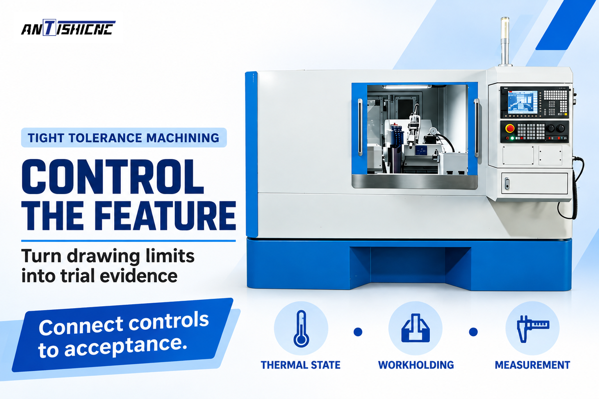
Tight tolerance machining keeps a critical feature within tight drawing limits for an agreed production run. Five controls carry the work: temperature, work holding, cutting, condition of the material and measurement. Start with the feature that must function, then connect each control to a measurable acceptance condition so the parts meet the drawing limits.
A single good sample isn’t sufficient for a machine buyer. A machinist wants to know which change to correct. This guide connects those decisions with a variation ledger, a process-selection matrix and a trial record.
- Critical feature: name the size, form or texture characteristic.
- Drawing limits: retain units and actual upper/lower values.
- Verification state: identify temperature and prescribed restraint.
- Release method: record sampling, uncertainty and the decision rule.
What tight tolerance machining means on the drawing
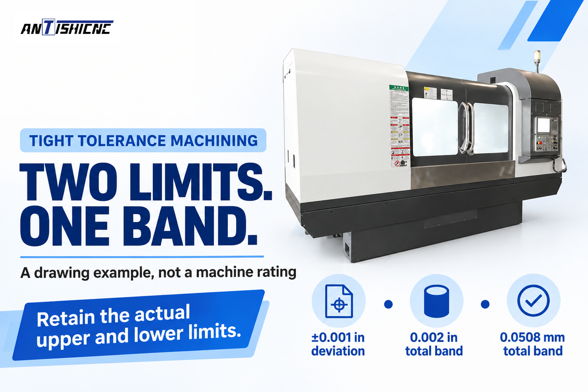
Tight tolerance machining begins with an explicit lower and upper limit for a feature of interest. A callout of ±0.001 in allows a total width of 0.002 in, or 0.0508 mm. Size, roundness, runout and surface texture describe different properties, so write each functional requirement before selecting a manufacturing route.
Precision machining controls the dimensions that let finished parts fit together. Tighter tolerances are useful in controlling bearing fit, alignment and seal interfaces; applying the same band to all surfaces of an assembly may add work, but may not improve the assembly. The role of tight tolerance is more functional control as opposed to a marking or ID attached to the part.
Keep the reference temperature with the definition of limits. ISO 1:2022’s public scope covers the reference temperature for geometrical and dimensional properties; NIST specifies 20 °C; the temperature correction and its uncertainty then belong in the measurement method.
What is considered tight machining tolerance?
A tight machining tolerance is a narrow permitted variation relative to the feature, material and production process. For example, ±0.005 mm gives a 0.010 mm total band. That requirement may be demanding on one feature and routine on another; the drawing limits and a repeatable measurement method give the useful definition.
Dimensioning must also locate the band; these tolerance requirements define the permitted sizes. A 1.000 in feature with +0/−0.002 in limits spans 0.998–1.000 in. A 1.000 ±0.001 in feature spans 0.999–1.001 in. Both have 0.002 in total width, yet their acceptable sizes differ. Replacing one with the other can change the fit. Use the datum and geometric tolerancing guide for form and location, and the general tolerances under ISO 2768 for drawing defaults.
A purchasing review places the critical feature with its mating feature. If the supplier gives a wider band, the design owner must check for clearances and/or interference. An allowable limit can’t be overcome by a low bid.
A ±0.001 in callout permits 0.0254 mm deviation in either direction; its full span is 0.0508 mm. Equal band widths can occupy different positions around nominal size. Copy the actual limits into the inspection plan so the buyer and supplier judge the same finished feature.
Temperature: separate part growth from machine drift
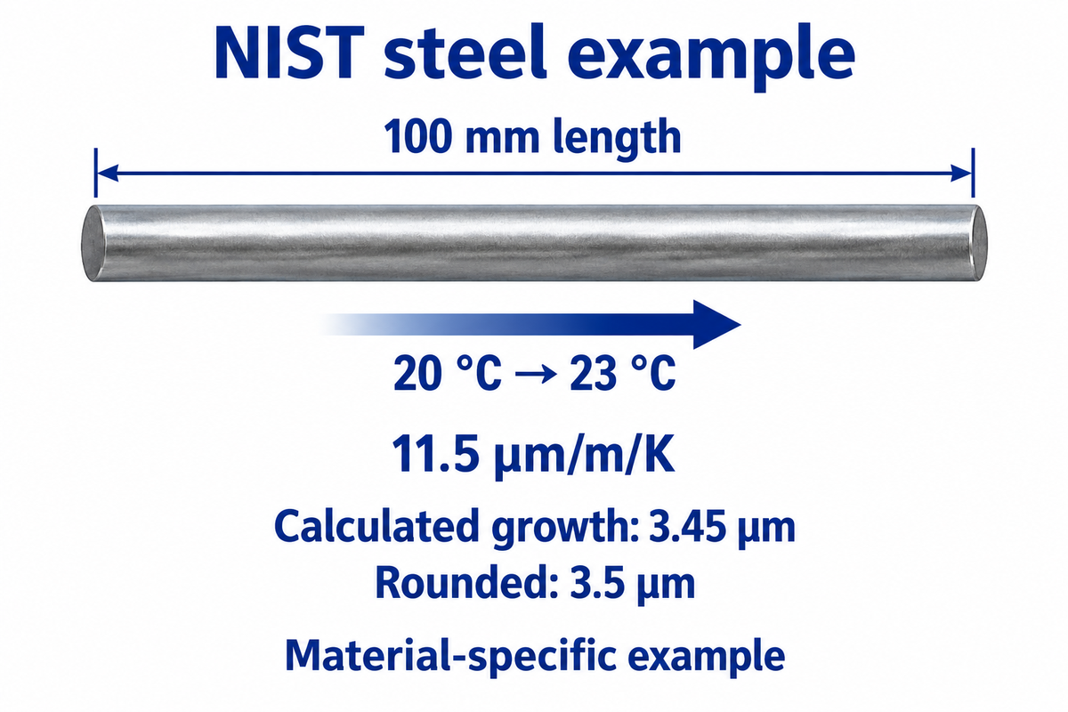
Temperature control begins by separating workpiece expansion from movement of the machine structure. In NIST’s steel gage-block example, a 100 mm length with a coefficient of 11.5 µm/m/K grows about 3.5 µm between 20 °C and 23 °C. Record both the material temperature and the machine’s running state before adjusting size.
Consider that 100 mm steel reference in a shop at 23 °C. The calculation is ΔL = αLΔT = 11.5 µm/m/K × 0.100 m × 3 K = 3.45 µm, rounded to 3.5 µm in the NIST dimensional-metrology FAQ. A reader comparing this value with a 0.005 mm allowance is comparing 3.45 µm with 5 µm. Before changing an offset, bring the reading to the defined reference condition or apply an appropriate correction. The coefficient belongs to the material example; use the actual alloy’s coefficient for another part. Uncertainty in that coefficient and in the temperature measurement remains after correction.
Timestamps should be added for coolant refills and restarts. In the bar-work discussion, it was mentioned that size changed. This led to temperature and vibration theories. The original poster hadn’t measured temperature. An adequate response is to record the event and capture the thermal state prior to choosing a cause. Carefully controlled room air alone leaves warm stock, coolant and spindle growth unresolved. Record those environmental conditions with the feature readings.
For the 100 mm steel example, the same coefficient gives 1.15 µm growth per 1 °C. Longer features accumulate more length change for the same temperature difference. Compare quotations on a stated reference condition and warm-up procedure, so extra environmental control addresses a measured contribution to the feature.
Workholding and cutting: isolate the source of variation
An effective diagnosis compares the feature before and after a controlled process change. A 2011 study of 120 mm forged steel disks showed how clamping, material removal and machining stress affected shape together. Process states should be recorded rather than assuming five independent and unrelated error sources. This approach should be coupled with an assessment of the restraint state required by the drawing.
The Steel-disk distortion study compared geometry of disks before and after various manufacturing steps. In a more recent Thin-wall milling study computer modeling was used to predict coupled phenomena of cutting and clamping, and to limit the scope of predictions to key clamping locations. Staged investigation was supported by both studies. Neither supplies a universal fixture pressure or a guaranteed diagnostic score.
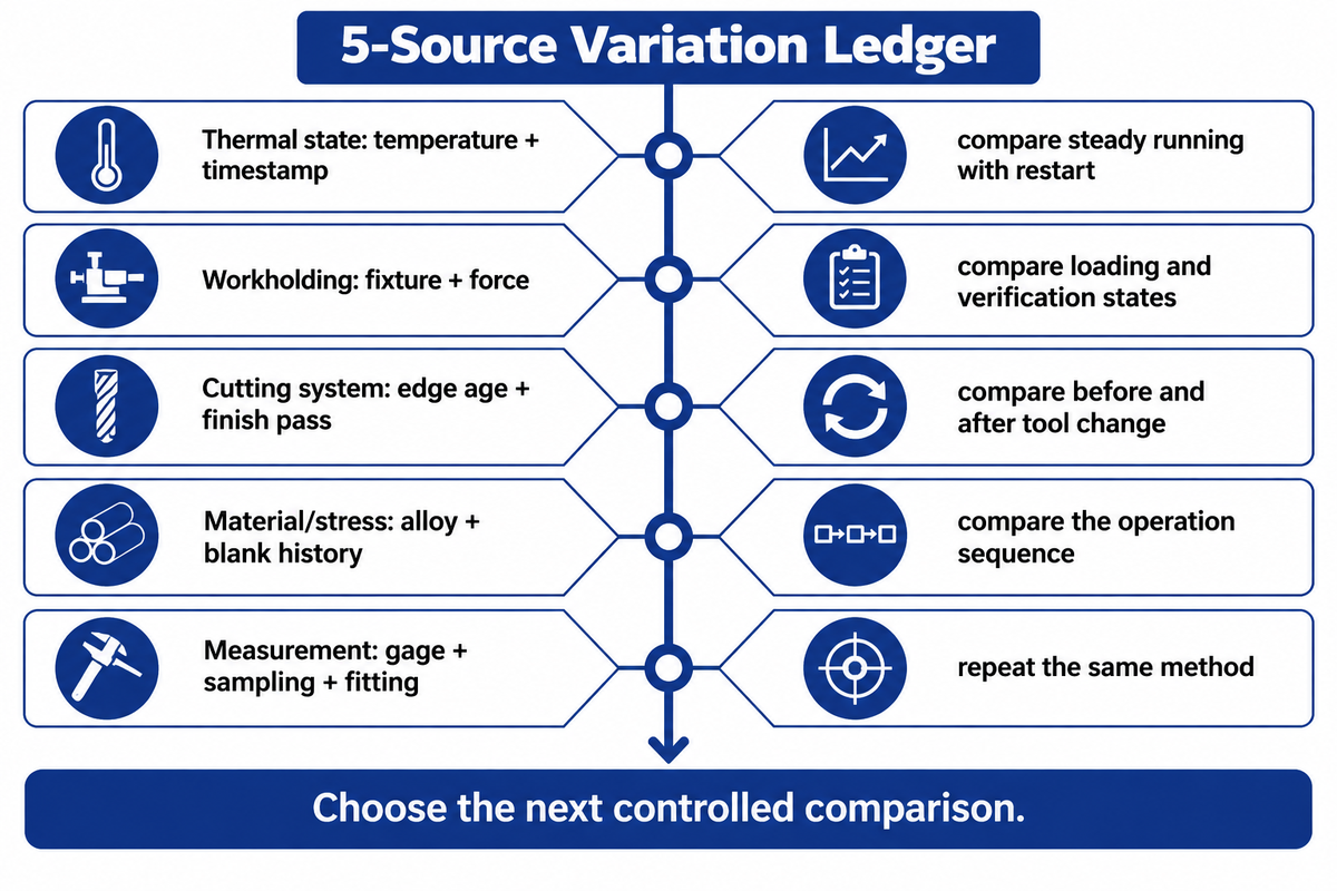
5-Source Variation Ledger
The 5-Source Variation Ledger links each suspected contributor to an observation and a controlled comparison.
| Contributor | Record | Compare | Response |
|---|---|---|---|
| Thermal state | Part/coolant temperature and timestamp | Steady running versus restart | Separate thermal recovery from permanent size correction |
| Workholding | Fixture, seating and approved force setting | Repeat loading; compare machining and drawing verification states | Review support and seating before offset changes |
| Cutting system | Edge age, tool identity and finish pass | Stable cuts before/after tool change | Separate edge-related steps from gradual drift |
| Material/stress | Alloy, heat and blank manufacturing history | Geometry across the approved operation sequence | Review stock allowance and treatment sequence |
| Measurement | Gage, sampling locations, fitting and restraint | Repeat the characteristic under the same method | Resolve method differences before chasing offsets |
A thin-wall ring can read round in a chuck and change shape after release. Use that difference to investigate fixturing, then inspect in the drawing’s specified state. ISO 10579:2010’s public scope covers non-rigid parts that require restraint during verification. Ordinary cutting clamping and the prescribed verification restraint are separate setup definitions.
History of material also belongs in the ledger. Surprising distortion occurred after turning powder-bed-fused stainless cylinders in NIST’s 2018 additive/subtractive study. Keep this in process scope. Use this for part design reviews to document how the raw material was formed. Choose a proper tool and support arrangement for the geometry; efforts to reduce tool wear cannot correct an unstable datum.
Measurement uncertainty and the release decision
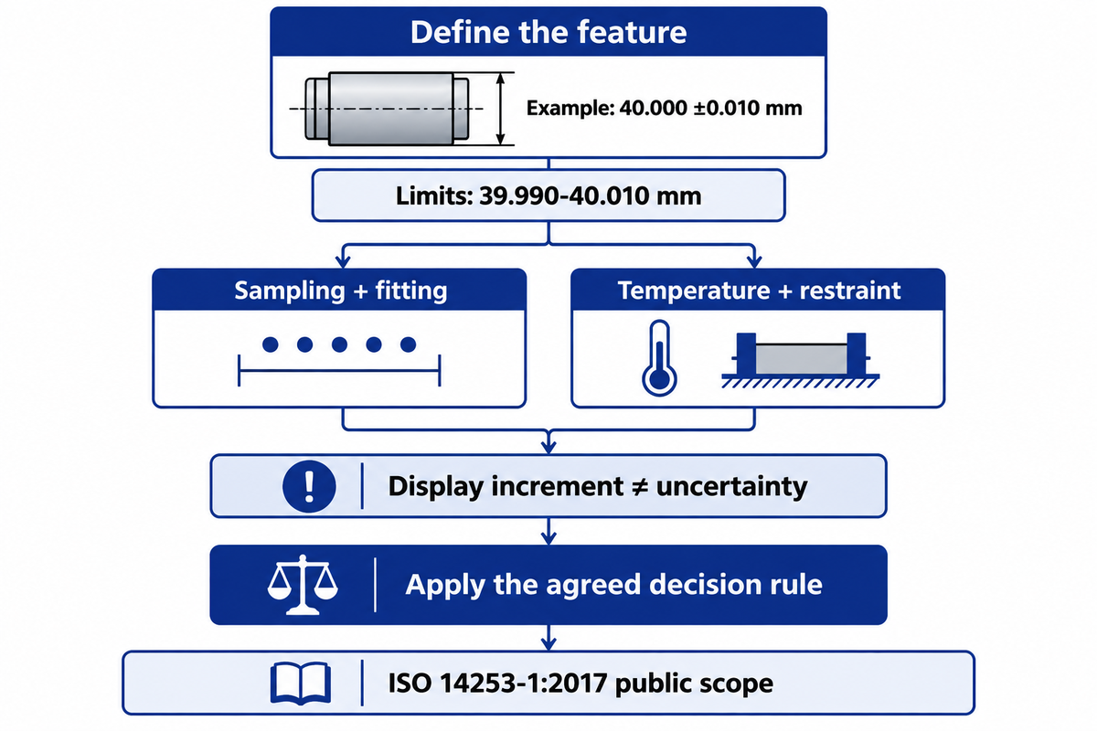
Measure and release a feature using the specified verification state and agreed decision rule. A display showing 0.001 mm increments doesn’t show the complete measurement uncertainty. Near a specification limit, calibration, temperature, sampling, and fitting can affect the decision even though repeated readings show consistency. Set those inspection requirements before the trial to improve part inspection consistency.
A diameter reading gauges size at sampled locations. Roundness, runout and position require different measurements. The NIST discussion of CMM geometric inspection gives insight into the discrepancy between an entire surface and a limited set of measurement points. Besides defining point distribution and the fitting method, specify the instrument. Legacy concentricity callouts also need the drawing’s stated standard and interpretation.
For a hypothetical 40.000 ±0.010 mm journal, the size limits are 39.990 mm and 40.010 mm. Let’s say a reading is made near the upper limit. In this case, per the agreed uncertainty-aware rule, metrology should treat that result as-is, instead of rounding it up for acceptance. ISO 14253-1:2017’s public scope addresses such conformance decisions. The requested measurement task may take advantage of a suitable in-machine system or another piece of equipment; choose the most appropriate system by evaluated performance for the characteristic.
The measurement plan for the 40 mm journal should keep size and form results separate. Traceability to calibration and the prescribed restraint should be agreed upon prior to purchasing extra decimal places on a display. More repeated readings at one point won’t replace coverage of the entire surface.
For the 40.000 ±0.010 mm journal, write the 39.990–40.010 mm limits, the drawing-specified restraint and the ISO 14253-1 decision rule in the same measurement plan. Instrument display increments and acceptance uncertainty are separate quantities.
Process capability: hold the band throughout the batch
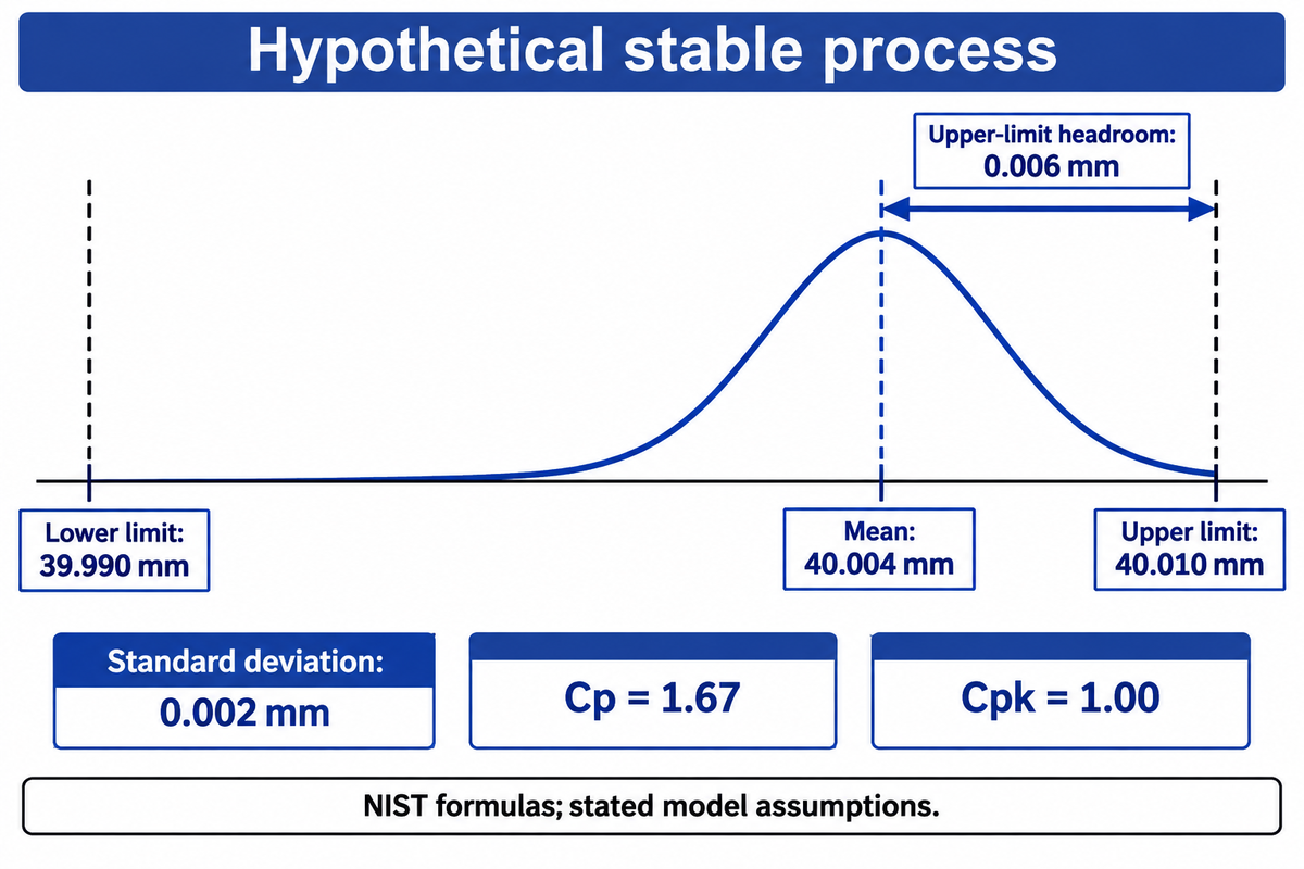
Maintaining tight tolerances requires consistent behavior over the production conditions being assessed. Cp compares the allowed width with process spread; Cpk also accounts for centering. For a hypothetical 40.000 ±0.010 mm feature with mean 40.004 mm and standard deviation 0.002 mm, Cp is 1.67 while Cpk is 1.00 under the stated statistical model.
“Also, we cannot begin to talk about process capability until we have demonstrated stability in our process.”
We assume a stable process and an approximately normal model with appropriate spread. The journal’s upper and lower limits are 40.010 mm and 39.990 mm. Cp = (40.010 − 39.990)/(6 × 0.002) = 1.67. For Cpk, compare (40.010 − 40.004)/(3 × 0.002) = 1.00 with (40.004 − 39.990)/(3 × 0.002) = 2.33; take the smaller result, 1.00. The NIST capability formulas show why a narrow spread can still sit too close to one limit. In this example, it is not the spread, but the centering that is the issue. A buyer-agreed acceptance criterion and sampling plan remain separate decisions.
Can a machine with ±0.02 mm accuracy make a part within ±0.01 mm?
A machine may meet a ±0.01 mm part requirement only if its validated cutting and measurement process holds that feature within the limits. A quoted ±0.02 mm machine metric, alone, gives very little information. It’s necessary to determine whether it specifies position of an axis, travel range of a mechanism or some other test. After this is determined, the actual feature and process conditions can be evaluated.
Compensation can address a measured, repeatable bias. Random variation, changing thermal state or an unstable fixture needs a different response. Keep accuracy and repeatability distinct. Statistical process control or SPC allows the time order to be maintained, so that a tool change or restart of the process, or a change of the material remains visible, instead of merging into an average.
A 40.004 mm process mean leaves 0.006 mm to the upper limit in the worked example. The mean would need to be centered in order to improve Cpk and leave Cp unchanged. Maintain the time order before interpreting either index. Also, agree on the acceptance threshold with the customer and the length of the study, rather than imposing universal values.
Turning or grinding: choose by the functional feature
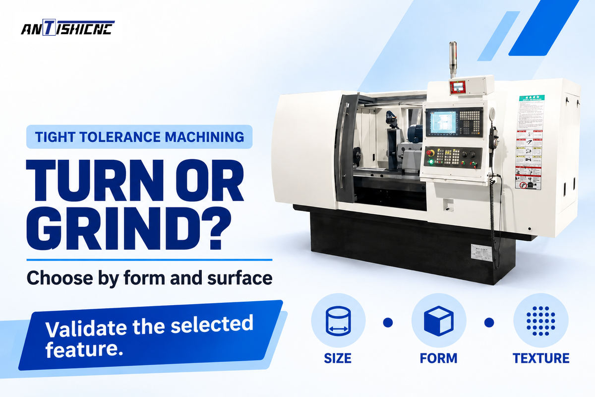
In terms of size, turning is a starting route for rotational features; cylindrical grinding earns its place when the required final form or surface state calls for it. A 0.010 mm size band alone can’t settle the route. Include hardness, access, datum relationships and texture, then assign a measurement result to each requirement before adding secondary processes.
- The feature is accessible to a supported cutting tool.
- Trial results meet size, form and texture together.
- The material state is suitable for the selected edge.
- Wheel access suits the final feature and datum.
- Grinding addresses the measured form or texture gap.
- Finishing stock and the treatment sequence are defined.
| Feature cluster | Likely constraint | Route to evaluate | Acceptance result |
|---|---|---|---|
| External bearing seat | Fit and datum runout | Finish turning or cylindrical grinding | Size, form and runout |
| Thin-wall ring | Fixture-induced shape change | Supported turning or grinding | Form in specified restraint |
| Long shaft | Support and slenderness | Supported turning; journal grinding | Straightness and journal relation |
| Hardened journal | Material state and surface integrity | Hard turning or grinding | Size, texture and relevant surface checks |
| Internal bore | Access and tool reach | Boring or internal grinding | Diameter, taper and form |
| Sealing surface | Texture and directional marks | Turning plus suitable finishing | Specified texture and surface condition |
| Planar face | Flatness and datum relation | CNC milling or surface grinding | Flatness and perpendicularity |
| Small profile/feature | Access and material conductivity | Swiss machining, milling or wire EDM | Profile, size and edge condition |
| Interrupted surface | Edge loading and local form | Evaluate cutting or grinding strategy | Feature consistency across interruptions |
In a precision CNC bearing-seat trial, the same requirement should be compared on the same blank condition. If size was passed but surface texture wasn’t, a finer size offset doesn’t address the surface texture requirement. ANTISHICNC’s CNC cylindrical grinders provide the required route; the CNC lathes provide the turning option.
Surface integrity can vary based on the route taken to reach the final dimension. A 2026 S13Cr stainless-steel study found varying surface and subsurface residual stress conditions after turning and grinding. Each value was a single observation and fatigue life wasn’t assessed. Selecting the feature’s functional evidence rather than claiming turning provides longer life is recommended. Aerospace components and medical devices require specialized validation beyond dimensional acceptance; this matrix selects manufacturing processes, not product qualifications.
Tight tolerance machining cost: quote only needed precision
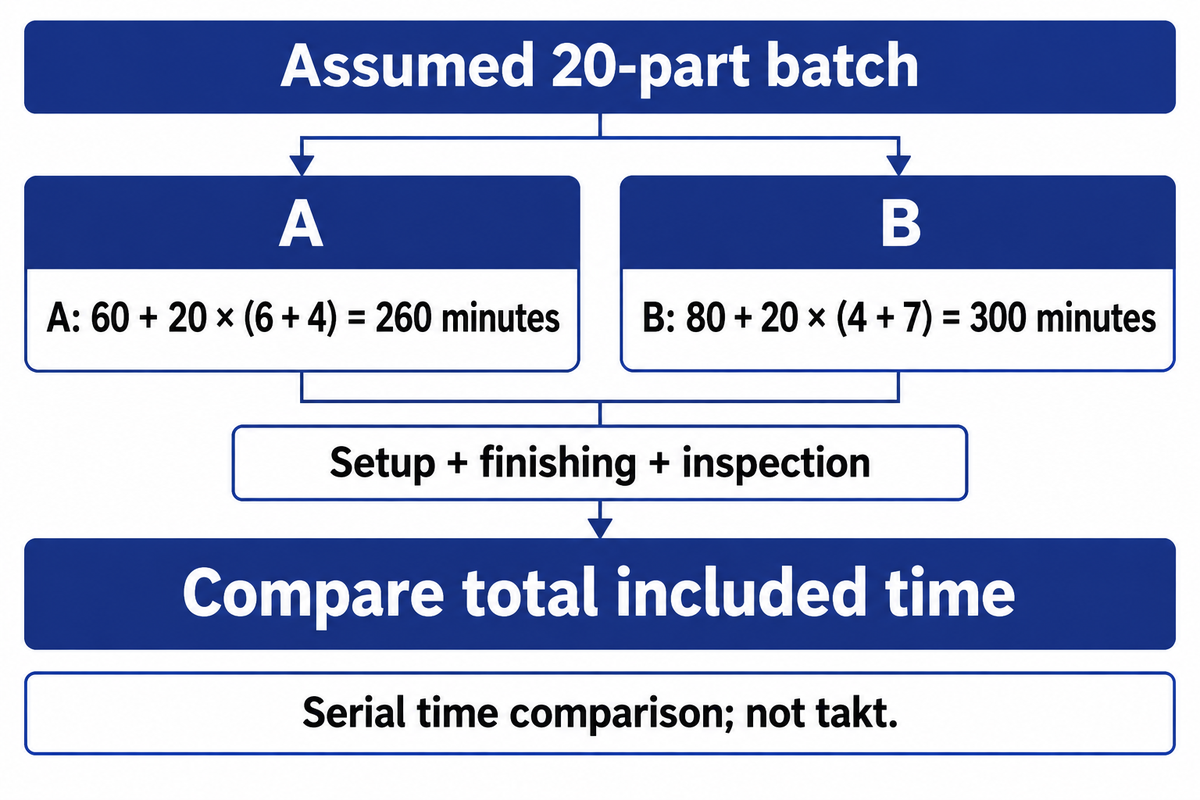
Cost of machining tight tolerance varies by quote and what work is included. In an assumed 20-part batch, 60 minutes of setup plus 6 minutes finishing and 4 minutes inspection per part totals 260 minutes. If setup and/or inspection time increases, the total paid time may increase even if the finishing time decreases. Keep the scope compared explicit.
Consider two proposed scopes for the same 20 parts. Scope A uses 60 minutes setup, 6 minutes finishing and 4 minutes inspection per part: 60 + 20 × (6 + 4) = 260 minutes. Scope B uses 80 minutes setup, 4 minutes finishing and 7 minutes inspection: 80 + 20 × (4 + 7) = 300 minutes. Finishing saves 40 minutes in B, but added inspection consumes 60 minutes and setup adds 20 minutes. Price scopes or labor hours by multiplying by an applicable rate. Parallel inspection would require a separate capacity calculation; this example compares included time, not takt.
The ASQ cost-of-quality framework separates prevention and appraisal costs from internal and external failure costs. For a prototype or low-volume order, ask which setup and measurement costs recur. Rework, rejected stock and expedited shipping also impact lead times and the supply chain. Compare CNC machining services on the same release scope; precision machining services that include form inspection are a different offer from a size-only check.
Scope B’s 4-minute finish is shorter than Scope A’s 6-minute finish, yet its 300-minute total exceeds 260 minutes for the same batch. Review manufacturability and part quality with the design owner before widening nonfunctional callouts, and preserve the critical limits that make the parts function as required.
Machine acceptance: agree the trial before the order
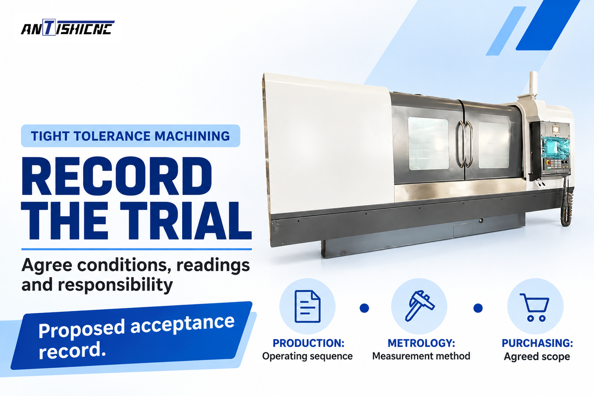
Machine acceptance requires a shared record of configuration, cutting conditions, and measured features.
Separate axis-positioning tests, standard test-piece cutting, and the buyer’s production-part trial. A proposed nine-condition record captures changes that a selected sample misses. Production owns the operating sequence, metrology owns the measurement method, and purchasing owns the agreed scope.
ISO 230-2:2014 covers axis positioning. ISO 13041-6:2009, confirmed in 2026, supplies minimum cutting-accuracy requirements for CNC turning machines and turning centres using standard finished test pieces. Add the actual part’s material, datum, restraint, sampling and uncertainty rules to the order. The production trial should address the events the shop will encounter. Tolerances in CNC machining belong beside the process conditions used to evaluate them.
9-Condition Acceptance Trial
The 9-Condition Acceptance Trial is a proposed record linking production events to measured features and agreed actions prior to a machine order.
| Condition | Record to retain | Decision owner |
|---|---|---|
| Cold start | Warm-up procedure and first usable feature results | Production |
| Steady running | Time-ordered size/form observations | Production + metrology |
| Travel position | Relevant cutting position and feature results | Metrology |
| Part reload | Datum seating and geometry in drawing-specified restraint | Production |
| Tool/wheel age | Drift through planned edge life or dressing interval | Production |
| Change or dressing | First accepted readings after intervention | Production |
| Stop/restart | Idle duration, thermal state and recovery results | Production |
| Coolant/ambient change | Timestamped temperatures and feature response | Production + metrology |
| Installed-site handover | Installation state and repeated agreed checks | Purchasing + metrology |
For equipment scope, ANTISHICNC’s CNC cylindrical grinder range describes CG45 with Siemens control and an optional measuring device. Put the required measuring option in the configuration line and specify the feature it measures. High-precision CNC machines require compatible workholding and metrology to achieve tight tolerances on the selected part.
For the study duration, sampling frequency, and reaction rules, reach agreement before each test. The quality management system should keep raw readings and interventions to allow OEMs to make release decisions. Shared standards for quality should name the characteristic and its release method.
2026 outlook: compensation needs measured feedback
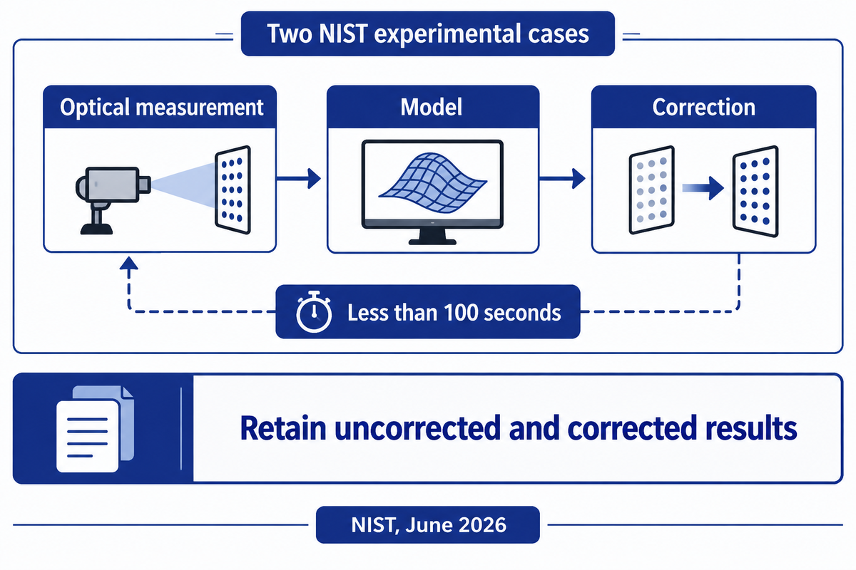
Buy feedback that measures the process change you want to control. NIST’s June 2026 thermal-deformation work describes compensation in less than 100 seconds for two experimental cases using optical measurement and modeling. The purchase question is how quickly a specified measurement is justified to become a correction while the machine and part change state.
The NIST 2026 study used a scaled standard test specimen and a bore-grid artifact to test compensation. The reported gains are from these experiments. For a 2026 equipment project, define the measured feature, the correction target, and the time window of applicability of the model. Improving the performance in one thermal state will help production only if the cell is in that state and the measurement arrives in time.
Modern manufacturing increases measurement within the cell, but helpful feedback requires a stable reference. A probe value can help with process adjustment, and final release is tied to evaluated measurement task and its decision rule. Keep correction history with part results. If tool changes create steps and the software assumes those changes are gradual thermal growth, a smooth compensation curve can mask the wrong cause.
Standard editions also warrant a look back. In October 2026, ISO 1:2022 remains the reference-temperature edition; ISO 230-2:2014 remains current, and ISO 13041-6:2009 was confirmed in 2026. Keeping an edition avoids the need to create a new set of cutting requirements. In the purchase contract, choose the scope of tests you will apply and keep the drawing edition requirements.
How a supplier explains a concept can be influenced by search interest. However, in the case of machine purchasing, the part and the trial ultimately dictate the outcome. No reliable year-over-year adoption rate for this compensation technology could be found in the research. The more appropriate next step for a new cell would be a timed feedback demonstration with retained measurements, rather than a market growth assumption.
A compensation cycle of less than 100 seconds in the NIST experiments connects sensing and correction for a specified task. A buyer should assess that time frame relative to the actual changes being controlled, and then retain the uncorrected and corrected results for the feature in question. The evidence suggests a measured feedback specification for the cell is warranted.
Frequently asked questions
Is .005 a tight tolerance?
A .005 callout needs a unit and a sign convention before it describes a usable tolerance.
What is the ISO standard for machining tolerances?
ISO machining requirements use different standards for general drawing limits, geometry, reference temperature and verification.
What is precision manufacturing and machining technology?
Precision manufacturing combines controlled processes and measurement to produce features within their specified limits.
What is High-Mix Low-Volume (HMLV) Manufacturing?
High-mix low-volume manufacturing produces many part variants in relatively small batches.
Which machining method is best for tight tolerances?
Choose the method that satisfies the feature’s size, geometry and surface requirements in its final material state.
What is the tightest machining tolerance?
The tightest useful tolerance is the smallest band the complete process can repeatedly manufacture and verify for the specified feature.
A ±0.010 mm feature has a 0.020 mm total band. Define its verification state, control process changes and retain the measurements that support acceptance before buying the machine.
If you’re considering a tight tolerance CNC machining cell, contact us with your critical feature drawing for a machine trial to discuss. Include the condition of the material, batch pattern and inspection requirements. Use the trial to evaluate the same equipment and measurement scope.
How this guide supports equipment selection
ANTISHICNC supplies metalworking equipment. This guide combines published metrology research and standard scopes with proposed trial records for tight-tolerance feature control. The numerical capability and time comparisons use stated assumptions. They help organize a machine purchase around the drawing, the workholding and the release method, with each decision assigned to production, metrology or purchasing.
References & Sources
- Dimensional-metrology FAQ National Institute of Standards and Technology
- Influence of turning on disk distortion, 2011 Kohlhoff, Sölter and Brinksmeier, Production Engineering
- Clamping-force prediction and coupled forces, 2023 Scientific Reports
- ISO 10579:2010, non-rigid parts, public scope International Organization for Standardization
- Residual stress in hybrid additive/subtractive manufacturing, 2018 National Institute of Standards and Technology
- Statistical issues in CMM geometric inspection, 1997 National Institute of Standards and Technology
- ISO 14253-1:2017, decision rules, public scope International Organization for Standardization
- Process stability, section 3.4.5 NIST/SEMATECH Engineering Statistics Handbook
- Process capability formulas NIST/SEMATECH Engineering Statistics Handbook
- Turning and abrasive finishing of S13Cr steel, 2026 Quintas, Lima and Fonseca
- Cost of quality American Society for Quality
- ISO 230-2:2014, axis positioning, public scope International Organization for Standardization
- ISO 13041-6:2009, finished test piece, public scope International Organization for Standardization
- In-process optical thermal-deformation compensation, June 2026 National Institute of Standards and Technology
- ISO 1:2022, reference temperature, public scope International Organization for Standardization