







If you know how to calculate SFM in theory but often second guess the number on your dial, work through this page step-by-step instead of skimming it. It’ll take you through the calculation to do it at the machine, then show you how to check your own work before hitting the cycle start; the idea here’s that it complements your other reference materials.
How to calculate SFM is a four-step process: find your diameter, pick a starting surface speed, run the formula, then verify your result before you cut.
Quick Specs
| Find RPM from SFM | RPM = (SFM × 3.82) ÷ Diameter (in.) |
| Find SFM from RPM | SFM = (RPM × Diameter (in.)) ÷ 3.82 |
| Need a material starting point? | See the cutting speed chart by material for the full table. |
This Page Teaches the Calculation Steps, Not Just the Formula
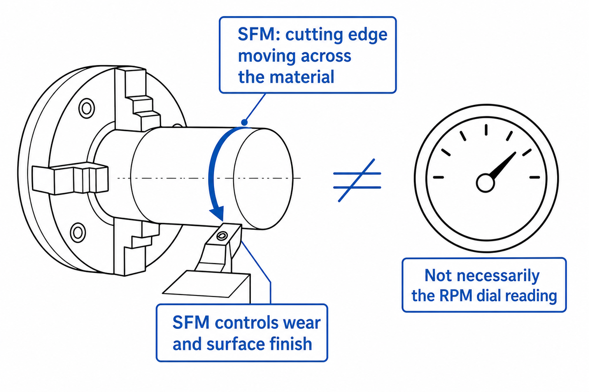
The goal of this page is to help you calculate both SFM and RPM for yourself with the help of these instructions, and verify your math before starting a cut – the page isn’t a chart to look up a speed or feed, or a general overview of why these numbers move together. Your actual cutting speed in SFM is the speed with which the actual cutting edge is moving across the material, and SFM controls both wear and how smooth your part’s surfaces come out; it’s not necessarily the RPM dial reading all by itself!
Imagine you made two seemingly identical-looking cuts at identical RPM, but they produced very different results in terms of tool wear, due to differing workpiece diameters or tooling O.D.’s; this is a situation this tutorial is designed to highlight. Some sources use other notation for surface speed, such as SFPM or SFM – either abbreviation refers to the same concept and usage, and for this material we’ll stick with SFM. If you want an explanation about basic feeds-and-speeds as a concept – such as cutting tool chip load or feed per revolution, and the factors influencing speed vs feed, you can consult our feeds and speeds fundamentals guide, as we’ll avoid repeating this information as much as possible here. Unlike a calculator app, this lesson also intends for you to be able to determine a speed setting without use of an outside computer and solely on paper, right at the machine.
The 4 Steps to Calculate SFM and RPM
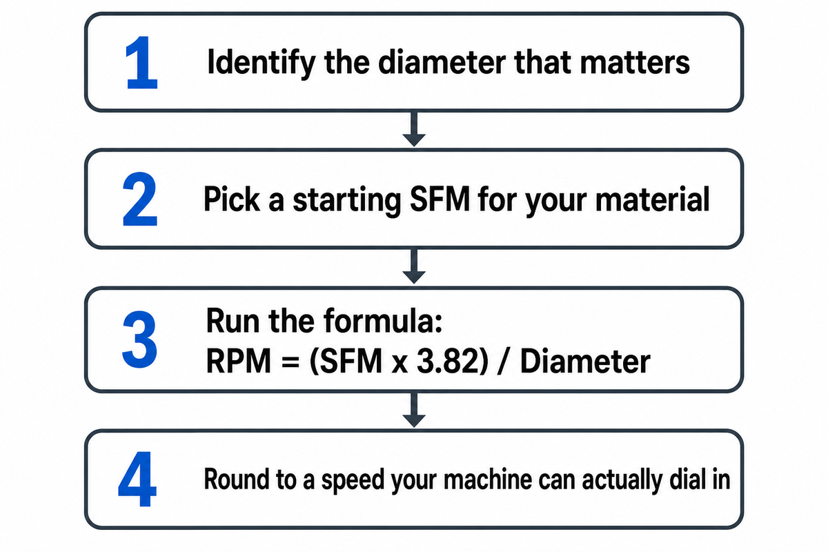
There are four sequential, essential steps required before your spindle is ready, all based on using a target or approximate SFM value: first find the diameter of the cut, next look for a starting point on the SFM chart, compute the setting with the formula below, and then ensure that the resulting SFM setting for your calculated spindle rpm is reasonable. Any one of those can cause an incorrect final calculation that can lead to an incorrectly set machine, so it’s more important that you don’t rush through these steps than it’s to memorize the math behind the formula.
- Identify the diameter that matters — on a lathe, that is the workpiece diameter; on a mill or drill, it is the cutting tool’s diameter. Using the wrong one is the single most common setup mistake (see the Sanity Check below).
- Pick a starting SFM for your material — use a reference table (see “Where to Get Your Starting SFM Number” further down) rather than guessing.
- Run the formula — RPM = (SFM × 3.82) ÷ Diameter, using diameter in inches.
- Round to a speed your machine can actually dial in — then confirm it against the 4-Point Sanity Check before you cut.
The constant 3.82 is not arbitrary. It comes from rearranging SFM = π × Diameter × RPM ÷ 12, the circumference of the workpiece or tool (π × D, in inches) times RPM gives inches traveled per minute, and dividing by 12 converts that to feet per minute. Flip the formula around to solve for RPM and 12 ÷ π rounds to 3.82. Three independent sources land on the same constant when you do that algebra: a University of Florida machining course, a Cutting Tool Engineering trade-press explainer, and Wikipedia’s own derivation, which is a reasonable amount of agreement for a formula you’re about to trust at the machine.
Where Does the 3.82 Constant Come From?
The 3.82 constant is 12 divided by π, rounded to two decimal places (12 ÷ 3.14159 = 3.8197…, rounded to 3.82). The 12 converts inches to feet, since there are 12 inches in a foot and machinists normally measure diameter in inches while SFM tracks feet per minute; the π comes from converting a diameter into a circumference, since the cutting edge travels around the full circumference once per revolution, not just across the diameter.
A University of Florida machining reference expresses the same relationship as N = 12V ÷ (π × D), which is algebraically identical once you solve for RPM; that cross-check is one of the reasons this page states 3.82 as a fixed constant rather than hedging it.
If you’d rather work in metric, the same combination of diameter and the velocity relationship holds: 1 SFM equals 0.00508 meters per second, the SI unit of speed, so you can convert a metric linear surface-speed measurement back to SFM by multiplying by roughly 196.85, or just switch to the metric form of the formula (RPM = 318 × m/min ÷ diameter in mm) instead of converting units mid-calculation.
“A 1-inch-dia. tool must run at 100 sfm. Based on the equation, that tool must turn at 382 rpm to achieve 100 sfm: 100 ÷ 1 × 3.82 = 382.”
— Christopher Tate, Cutting Tool Engineering
Worked Example, Turning on a Lathe
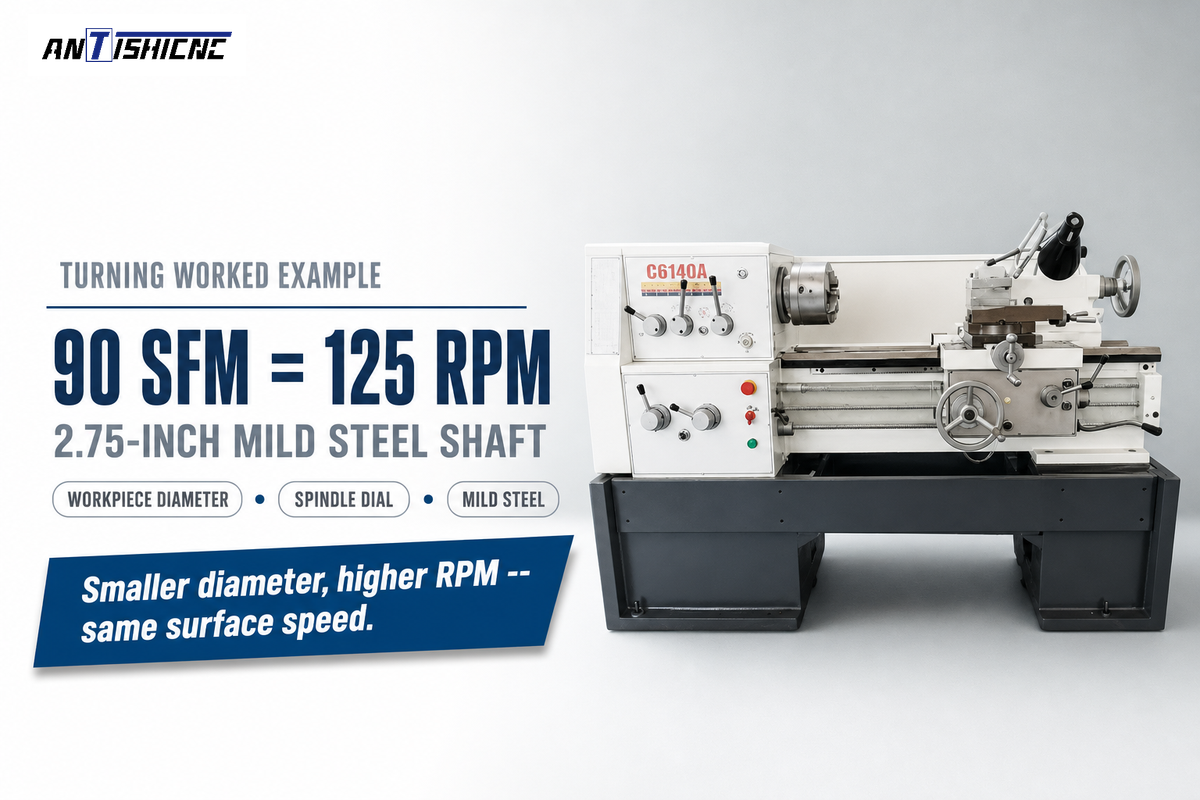
Here is how to calculate SFM for turning specifically: on a lathe, the workpiece rotates and the tool remains stationary, so the diameter that matters is the workpiece’s outside diameter – not the tool’s. Suppose you’re turning a 2.75-inch mild steel shaft on a metal turning lathe and want to start at a conservative 90 SFM. Multiply 90 by 3.82 to obtain 343.8, then divide by the 2.75-inch diameter: 343.8 ÷ 2.75 = 124.8, which you would round to 125 RPM on the spindle dial.
That’s the entire calculation for turning – only the workpiece diameter and the chosen SFM for the material and tool matter for each job. If the bar stock changes to 1.5 inches but you want the same 90 SFM, the spindle speed jumps to 90 × 3.82 ÷ 1.5 = 229.2, rounded to 229 RPM. Smaller diameter, higher RPM, same surface speed – that relationship is good to know because it is also where the most common calculation error occurs (see the Sanity Check below).
Worked Example, Milling
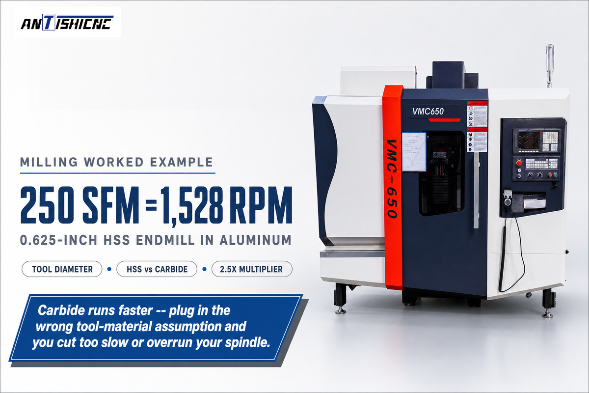
The steps to calculate SFM for milling flip one detail: on a mill, the tool rotates and the workpiece stays still, so the diameter that matters flips to the cutting tool’s diameter, the opposite of turning. The milling formulas below work the same way whether you are on a manual knee mill or a CNC machine running a complete milling operations program; the calculations don’t change, only how you input the number. Suppose you are cutting a 0.625-inch (5/8″), 2-flute HSS endmill in aluminum and want to start at 250 SFM, a typical HSS starting figure for aluminum. RPM = 250 × 3.82 ÷ 0.625 = 955 ÷ 0.625 = 1,528 RPM.
Swap that same endmill for a carbide version and the recommended surface speed moves up too, typically to somewhere around 2 to 2.5 times the HSS figure for the same material (more on that multiplier in “Where to Get Your Starting SFM Number” below). At 2.5×, that’s 625 SFM, which for this same 0.625-inch tool works out to 625 × 3.82 ÷ 0.625 = 3,820 RPM, more than double the HSS setting for the identical cut. That’s a large enough jump that plugging in the wrong tool-material assumption is a real, not theoretical, way to end up cutting far too slow or trying to run faster than your spindle allows.
🔎 Boundary condition: this arithmetic assumes the tool’s nominal diameter is the diameter actually doing the cutting. For a ball-nose or other contoured cutter working at a shallow depth of cut, that assumption can break down: the effective cutting diameter at the actual point of contact is smaller than the tool’s full nominal diameter, so a calculation based on nominal diameter alone will overstate your real SFM by a meaningful margin. Machining literature on ball-end milling documents this geometry effect, though the exact size of the gap varies by depth of cut and is specific enough to each setup that this page won’t attach one universal percentage to it. Flat end mills and standard drills don’t have this problem; it only bites on curved cutting edges.
Going the Other Direction, Finding SFM From a Known RPM
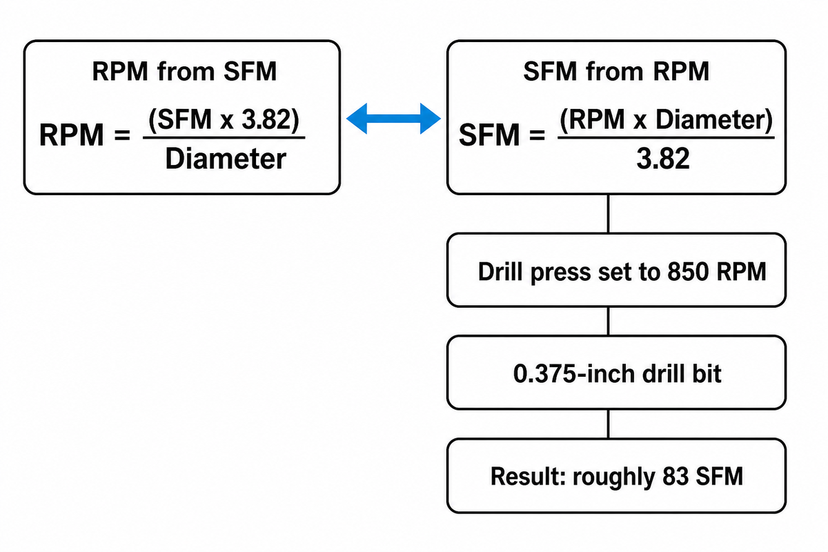
Sometimes you already know the RPM, maybe it’s what the last operator left the machine set to, and you want to know what SFM that actually represents before deciding whether to trust it. The formula rearranges cleanly from the same surface-speed relationship used throughout this guide: SFM = (RPM × Diameter) ÷ 3.82.
Say a drill press is set to 850 RPM and you’re about to run a 0.375-inch (3/8″) drill bit. SFM = 850 × 0.375 ÷ 3.82 = 318.75 ÷ 3.82 = 83.4, so that setup is running at roughly 83 SFM. If the machine only offers fixed steps and the nearest ones are 700 RPM and 1,000 RPM, you’d round down to 700 RPM (about 69 SFM) rather than up, since running slightly under target SFM is safer than running over it. Drilling uses the same core formula as turning and milling, the diameter you plug in is the drill’s diameter, since the cutting edge is at the outside of the bit. Reaming and tapping follow the same math but conventionally run at a fraction of the drilling SFM for the same material (see the FAQ below for a specific case).
The 4-Point Sanity Check
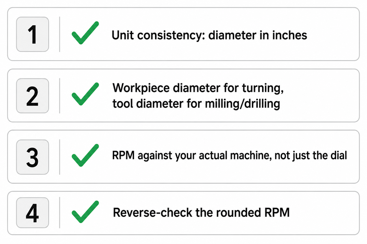
Calculating a number isn’t the same as trusting it. Before you commit a calculated RPM to the spindle, run it through the 4-Point Sanity Check four quick questions that catch the mistakes that actually happen at the machine, not hypothetical ones.
- Unit consistency – your diameter is in inches, not feet or millimeters? The 3.82 constant only works with inches; feed it a 12.7 mm value where you meant 0.5 inches and the resulting RPM comes out roughly 25 times too high.
- Did you use the workpiece diameter for turning and the tool diameter for milling or drilling, not the other one? Machinists commonly report this diameter mix-up as the single most repeated real-world mistake in SFM calculations, ahead of any arithmetic error.
- RPM against your actual machine, not just the dial – a mathematically correct RPM isn’t automatically a safe RPM to run. Check it against your spindle’s real speed range and against your chuck or workholding’s rated speed, which is frequently lower than the spindle’s mechanical maximum – a spindle mechanically capable of 4,000 RPM might sit behind a 3-jaw chuck rated for only 2,500 RPM, and the chuck rating is the one that governs.
- Reverse-check – plug your rounded RPM back into the SFM formula and confirm you land close to your original target SFM. For the turning example above, 125 RPM × 2.75 ÷ 3.82 = 90.1 SFM, close enough to the 90 SFM target to trust the rounding. A large mismatch, say more than 5-10%, off means a unit or diameter slip happened somewhere in steps 1-3.
The unit-confusion and diameter-mixup failure modes in points 1 and 2 are also the two most commonly reported real-world SFM mistakes across independent machinist write-ups and shop-floor discussions – not a hypothetical list, but a pattern that repeats often enough to be worth a dedicated check every time, not just when a job feels unfamiliar.
Where to Get Your Starting SFM Number

The formula only gets you as far as the SFM you feed into it, and that number depends on material and tool. The table below is a set of HSS starting points from a university machining reference, benchmarked on the same one-hour tool-life convention defined by ISO 3685, the international standard for single-point turning tool-life testing; treat every value as a starting point to fine-tune from, not a fixed rule.
| Material | HSS starting SFM | Limitations / Not suitable for |
|---|---|---|
| Aluminum and alloys | ~250 | Gummy/high-silicon alloys need lower speeds and sharper geometry — not a blanket number |
| Mild steel (0.2–0.3% C) | ~100 | Not for cold-drawn/hardened variants of the same nominal grade |
| Steel (0.4–0.5% C) | ~60 | Drops further for alloy or heat-treated steels in this carbon range |
| Cast iron (soft) | ~100 | Not for chilled or hardened cast iron surfaces |
| Cast iron (medium hard) | ~80 | Verify hardness before assuming this tier |
| Cast iron (hard chilled) | ~20 | Run dry where possible; coolant on chilled iron can thermal-shock the surface |
| Stainless steel (free-machining) | ~40 | Not for work-hardening stainless grades — see next row |
| Stainless steel (work-hardening) | ~20 | Never let the tool dwell or rub — that is what triggers work hardening in the first place |
For the full material table including additional alloys and both HSS and carbide columns side-by-side, see the cutting speed chart by material – this page keeps the headline numbers here so you’re not stuck without a starting point, but the fuller reference lives there.
Switching from HSS to carbide tooling changes what SFM you should plug in for the same material. One university machining reference gives a clean rule of thumb: multiply the HSS surface speed by roughly 2.5 for carbide. Other sources report a wider range: some put carbide-tipped cutters anywhere from 3 to 10 times HSS speed depending on coating and application, so there’s no single number every source agrees on, and the higher the SFM you attempt without matching tooling and rigidity, the more likely you’re to shorten tool life instead of saving time — the same economic tradeoff a peer-reviewed cutting-speed-selection study documents. Treat 2.5× as a reasonable starting multiplier, not a guarantee or a manufacturer’s formal recommendation, and confirm the optimal setting for your specific material and setup by watching tool wear on your first few passes rather than trusting the number alone.
The table below turns the same formula into a ready-made lookup: pick your diameter and target SFM setting, read off the RPM directly, and use it to sanity-check any value you calculate by hand — the 0.625-inch and 2.75-inch rows match the milling and turning worked examples above exactly.
| Diameter | 60 SFM Setting | 90 SFM Setting | 150 SFM Setting | 250 SFM Setting |
|---|---|---|---|---|
| 0.125 in | 1,834 RPM | 2,750 RPM | 4,584 RPM | 7,640 RPM |
| 0.25 in | 917 RPM | 1,375 RPM | 2,292 RPM | 3,820 RPM |
| 0.375 in | 611 RPM | 917 RPM | 1,528 RPM | 2,547 RPM |
| 0.5 in | 458 RPM | 688 RPM | 1,146 RPM | 1,910 RPM |
| 0.625 in | 367 RPM | 550 RPM | 917 RPM | 1,528 RPM |
| 0.75 in | 306 RPM | 458 RPM | 764 RPM | 1,273 RPM |
| 1.0 in | 229 RPM | 344 RPM | 573 RPM | 955 RPM |
| 1.5 in | 153 RPM | 229 RPM | 382 RPM | 637 RPM |
| 2.0 in | 115 RPM | 172 RPM | 287 RPM | 478 RPM |
| 2.75 in | 83 RPM | 125 RPM | 208 RPM | 347 RPM |
SFM vs Feed Rate (Chip Load) — Two Different Numbers
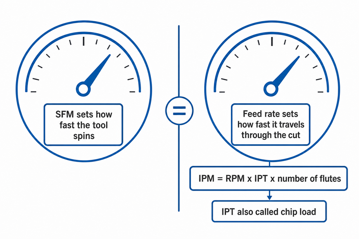
SFM and feed rate answer two different questions, and it is a mistake to combine them that is independent of anything covered by the Sanity Check above. SFM tells you how fast the cutting edge should be moving through the material, which the formula above then converts into a spindle RPM. Feed rate, how fast the table or workpiece advances, usually expressed as IPM (inches per minute) — is a second, independent calculation built from IPT (inches per tooth, also called chip load) and flute count, not from SFM at all: IPM = RPM × IPT × number of flutes. For a 4-flute endmill running 1,528 RPM (the milling example above) at a 0.003-inch chip load, that works out to 1,528 × 0.003 × 4 = 18.3 IPM.
Think of it as two separate dials on the same machine: SFM sets how fast the tool spins, feed rate sets how fast it travels through the cut. It’s simple feed rate x (depth of cut x width of cut) that’s MRR and helpful when guessing tool cycle time but it’s not why you’re trying to calculate SFM / RPM in the first place. Getting SFM right and feed rate wrong (or vice versa) still produces a bad cut – you have to calculate and check the two numbers independently, then combine them. Your tool manufacturer’s catalog usually lists a recommended IPT starting point per tooth for their specific inserts, which is worth checking before you rely on a generic figure. A feed rate calculator or a general speeds and feeds calculator can automate this second half of the math once you already trust the SFM number this page walked you through.
Frequently Asked Questions
Q: How do I convert RPM to SFM?
Multiply your RPM by the diameter in inches, then divide the result by 3.82 to get SFM; for turning use the workpiece diameter, and for milling or drilling use the tool’s diameter instead, since the formula stays the same.
Q: Is SFM the same as RPM?
No, SFM measures how fast the cutting edge moves through the material, while RPM measures how fast the spindle rotates, and the two numbers only match at one specific tool or workpiece diameter, which is why RPM alone tells you nothing about actual cutting speed.
Q: What is the formula for calculating cutting speed?
SFM equals RPM times the diameter in inches, divided by 3.82, where that 3.82 constant comes from 12 divided by pi rounded to two decimal places; the same formula rearranges to solve for RPM if you already know your target SFM instead.
Q: Is diameter in feet or inches for the SFM formula?
Inches, always inches; the 3.82 constant already handles converting that inch measurement into a feet-per-minute surface speed, so plugging in a metric or foot-based diameter by mistake is one of the most common setup errors machinists make.
Q: Does this formula work for tapping or reaming?
Yes, the same RPM and SFM formula applies to tapping and reaming, but both operations conventionally run at a slower SFM than straight drilling in the same material, since thread pitch, tap style, and chip evacuation limit the practical speed more than the formula does.
Q: Practice problem, a 3/4″ drill runs at 1,800 RPM. What SFM is that?
About 353 SFM: work it with SFM = (RPM × Diameter) ÷ 3.82, using the 0.75-inch drill diameter, which comes out fast enough for most steels at that size that the 4-Point Sanity Check would flag it for a second look before you trust it.
SFM = (RPM × Diameter) ÷ 3.82 gets you a number in seconds — the 4-Point Sanity Check is what turns that number into one you can trust enough to actually cut.
Why We Write This
The question is one we hear every day here at ANTISHICNC from those ready to commission one of our CNC lathes or mills: “how do I know which RPM setting to use?” This guide provides the answer we give – step-by-step methodology with an included check – not a surface-level online interpretation.
References & Sources
- Surface feet per minute Wikipedia
- Speeds and feeds Wikipedia
- Understanding Cutting Equations for Feeds and Speeds Christopher Tate, Cutting Tool Engineering
- CNC Milling Machine Tutorial University of Florida, Advanced Manufacturing / Design Lab
Related Articles
- Feeds and Speeds Explained the full concept guide, including feed rate and chip load
- Cutting Speed Chart for Metals (SFM by Material) the complete material and tool-type reference table
Browse Our CNC Lathe Lineup →
Alternatively, if you’re sizing a machine and need to work off this guide to select the appropriate speed range: take a look at the maximum spindle RPMs found on our CNC lathe lines.