




Updated October 2026
Machining Inconel is difficult because concentrated heat, high cutting forces, material condition, and tool-workpiece chemistry interact at the cutting edge. These alloys, particularly nickel-based superalloys, are used for corrosion resistance at high temperatures. However, they complicate the CNC machining process. Stable Inconel cuts begin with the right Inconel grade, tooling, and a measured trial.
Why Inconel Punishes the Cutting Edge
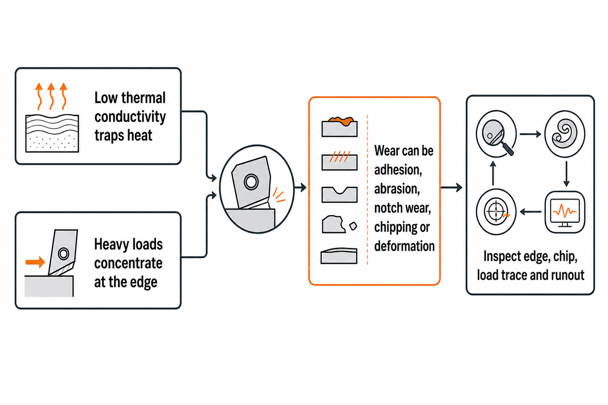
Low thermal conductivity creates unique challenges because it traps heat while heavy loads concentrate at the edge. Inconel superalloys retain strength at elevated temperature. Work hardening can develop alongside adhesion, abrasion, diffusion, oxidation, notch wear, chipping, and plastic deformation. These coupled mechanisms narrow the process window, so control heat, load, and edge condition through the tool, holder, coolant, and machine.
A September 2025 open-access review places machining difficulty inside the alloy’s wider thermal, microstructural, and processing behavior. It doesn’t assign one universal hardened-layer depth or interface temperature, so diagnosis must start with the observed edge, chip, surface, and load.
Common mistake: during Inconel work, lowering feed rate may create rubbing while chipping from runout, impact, or a weak holder continues. Begin inspection with the edge, chip, load trace, and runout.
Evidence boundary: separate heat and load from the visible failure, then test one correction against the same inspection criteria; no single wear mechanism or subsurface depth applies to every nickel alloy, operation, and cooling method.
Inconel 718 vs 625: Grade and Condition Change the Cut
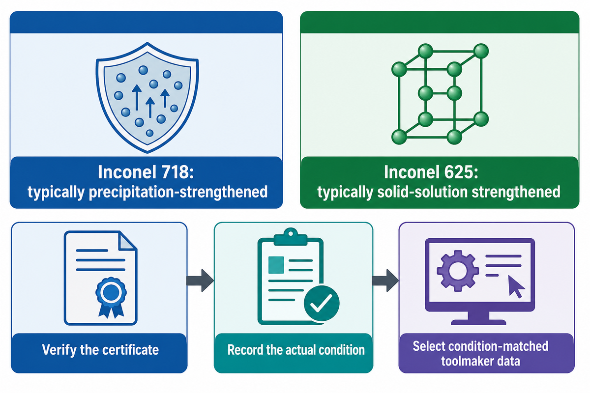
Compare Inconel alloys by grade and condition because an AISI machinability index or general machinability rating cannot describe every supplied state. Inconel 718 is typically precipitation-strengthened; solid-solution strengthening is typically the case for Inconel 625. Chemistry, heat treatment, tensile properties, product form, and prior processing can change tool wear.
| Check before programming | Inconel 718 | Inconel 625 | Programming action |
|---|---|---|---|
| Strengthening state | Solution-treated or aged conditions differ | Solid-solution effects often dominate, but aging history still matters | Record the actual condition |
| Material identity | Specification and heat/lot | Specification and heat/lot | Verify the certificate |
| Transfer rule | Do not transfer an aged-data line to solution-treated stock | Do not assume every supplied condition behaves alike | Select current, condition-matched toolmaker data |
How the Strengthening Condition Changes the Cut
A 2025 Inconel 718 study noted that in the case of wear and roughness, these parameters did not move together in wrought, additive, and heat-treated conditions. The study on Alloy 625 aging reported condition-dependent precipitation. Keep the certificate and condition next to the program revision for grades of Inconel.
Choose the Tooling System, Not Just the Insert
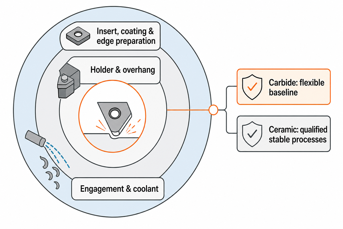
Choosing carbide or ceramic for Inconel includes consideration of carbide inserts, coated tools, edge preparation, lead angle, holder, overhang, engagement, and coolant. Carbide tools provide a flexible baseline; ceramic tools fit qualified stable processes. Impact, interrupted contact, weak fixturing, or thermal shock can erase the ceramic advantage.
There are no universal solutions for Inconel, so use current data to select the right tools and tool geometry, then confirm the surrounding cutting-tool types. This is a decision map, not a feeds-and-speeds chart.
Carbide and Ceramic Choices by Stability
| Cut situation | Practical baseline | System check before trial |
|---|---|---|
| Continuous turning | Coated carbide; qualified ceramic | Lead angle, support, coolant |
| Interrupted turning | Tough carbide | Impact and entry |
| Stable face milling | Carbide or qualified ceramic | Runout, engagement |
| Variable pocket | Carbide end mill | Toolpath, chip recutting |
| Drilling operations | Matched carbide drill | Coolant, evacuation |
| Thin wall | Sharp carbide | Support, deflection |
| Long overhang | Tough carbide | Interface, vibration |
| Heavy roughing | Supported edge | Torque, chip space |
| Finishing | Sharp radius | Wear, surface plan |
Consider an interrupted shoulder: replacing carbide with ceramic can raise speed yet lose edges at re-entry. A 2025 Sandvik Coromant application article published by Aerospace Manufacturing and Design separates ceramic rough or intermediate removal from sharper carbide semi-finishing and cautions that thin walls need different treatment. The evidence supports a system decision, not a universal ceramic speed multiplier.
Set Speeds and Feeds Without a Magic Number
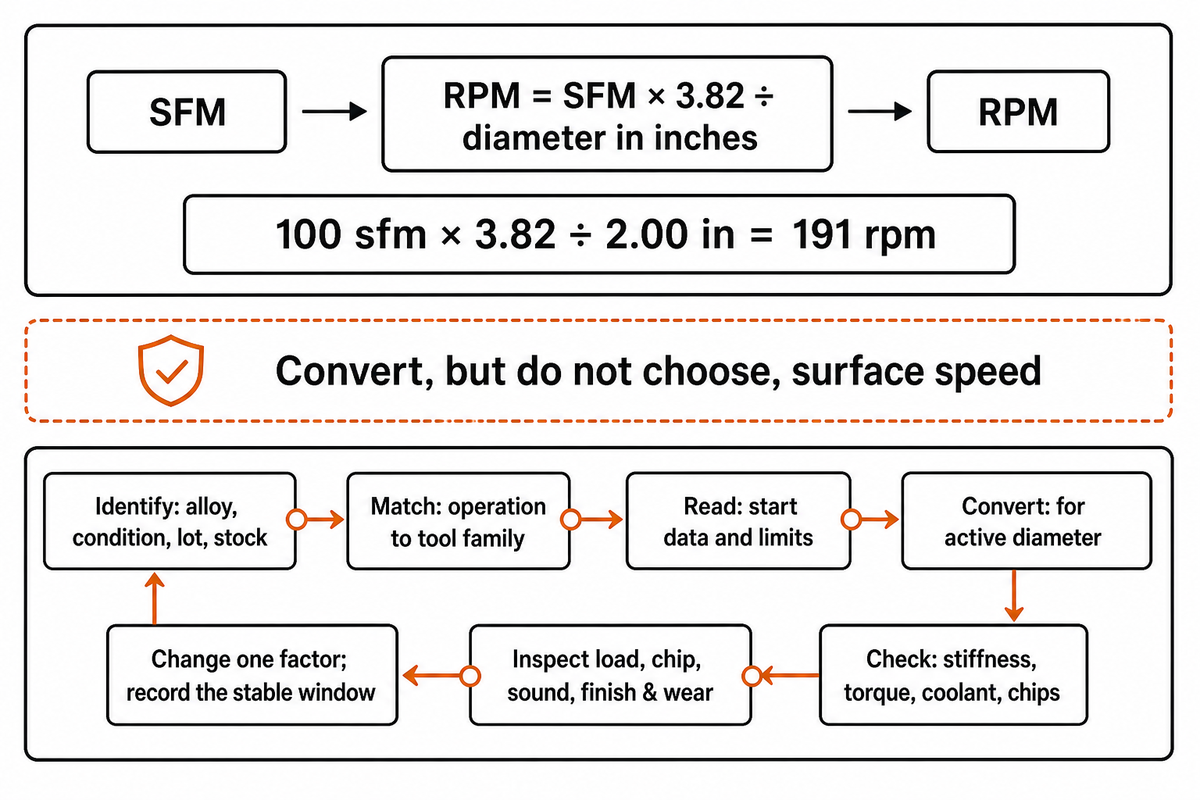
Start with current data for the grade, tool, operation, diameter, engagement, and coolant. Whether cutting Inconel by conventional machining or another qualified route, convert the real setting, check machine limits, run a short trial, and judge machining efficiency from edge, chip, load, sound, and surface finish.
RPM = SFM × 3.82 ÷ diameter in inches. These machining tips start with a limit: the formula converts, but does not choose, surface speed. Please see how to calculate SFM for the formula and conversion to metric.
Suppose toolmaker data gives 100 sfm at a 2.00 in active diameter. The arithmetic is 100 × 3.82 ÷ 2.00 = 191 rpm. This calculation only converts; check usable torque and retain all source limits.
The 7-Step First-Cut Sequence: Tips for Machining Inconel
- Identify — alloy, condition, lot, stock.
- Match — operation to tool family.
- Read — start data and limits.
- Convert — for active diameter.
- Check — stiffness, torque, coolant, chips.
- Inspect — load, chip, sound, finish, wear.
- Change one factor — record the stable window.
Evidence boundary: one study moved from 0.08 to 0.24 mm/rev while roughness rose from 0.75 to 1.2 µm Ra. The result stays with its tested configuration.
Turning, Milling, and Drilling Need Different Controls
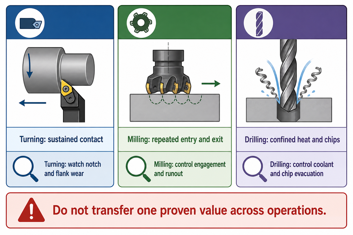
Turning, milling, and drilling operations expose the edge to different contact cycles and chip paths. Turning may sustain contact; milling adds repeated entry and exit; drilling confines heat and chips. Maintain positive chip formation while adjusting engagement, high-pressure coolant delivery, inspection and exit strategy. Use peck drilling only if drill guidance allows it.
| Operation | Primary control | Watch first | Avoid |
|---|---|---|---|
| Turning | Stable entry, supported insert, chip direction | Depth-line notch and flank wear | Dwelling on the diameter |
| Milling | Engagement and runout | Entry chipping and recut chips | Abrupt engagement swings |
| Drilling | Coolant-at-edge and chip evacuation | Thrust trend, chip packing, corner wear | Blindly applying one peck cycle |
A shop moving a proven turning value into a four-flute milling cut changes the thermal cycle, chip thickness, and impact pattern all at once. A safer handoff uses the operation-specific guidance in CNC turning and milling, then returns to the selected cutter maker for the actual grade and engagement.
Can Your Machine Hold the 3-Zone Inconel Heat-Load Window?
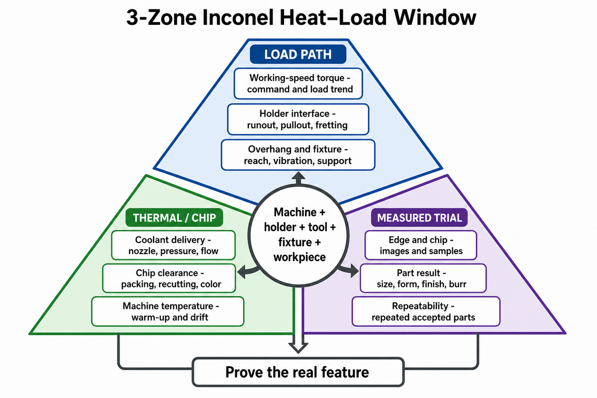
A machine is ready for Inconel parts only when the setup can hold load-path stability, thermal and chip control, and measured trial behavior all at once. Brochure horsepower, mass, taper size, or maximum coolant pressure can’t prove this. Capability belongs to the machine-holder-tool-fixture-workpiece system at the intended cut.
The 3-Zone Inconel Heat-Load Window is a practical checklist, not a certified model. Use it to frame a trial for a metal milling machine or existing cell; this is the machine, tool, and part evidence that Inconel machining needs.
| Zone | Evidence item | What to record on the real feature |
|---|---|---|
| Load path | Working-speed torque | Command and load trend |
| Load path | Holder interface | Runout, pullout, fretting |
| Load path | Overhang and fixture | Reach, vibration, support |
| Thermal/chip | Coolant delivery | Nozzle, pressure, flow |
| Thermal/chip | Chip clearance | Packing, recutting, color |
| Thermal/chip | Machine temperature | Warm-up and drift |
| Measured trial | Edge and chip | Images and samples |
| Measured trial | Part result | Size, form, finish, burr |
| Measured trial | Repeatability | Repeated accepted parts |
A NIST study connects stability to speed and overhang. Use a vertical machining center buying guide, then prove the feature with the real holder, fixture, and coolant path.
Evidence boundary: ISO 230-3:2020 addresses machine-tool thermal effects but supplies no Inconel horsepower, coolant-pressure, runout, or overhang threshold. Record temperature, torque, vibration, wear, and part results under the exact process setup.
The Signal-Based Tool-Wear Decision Tree: Change the Cause, Not the Symptom
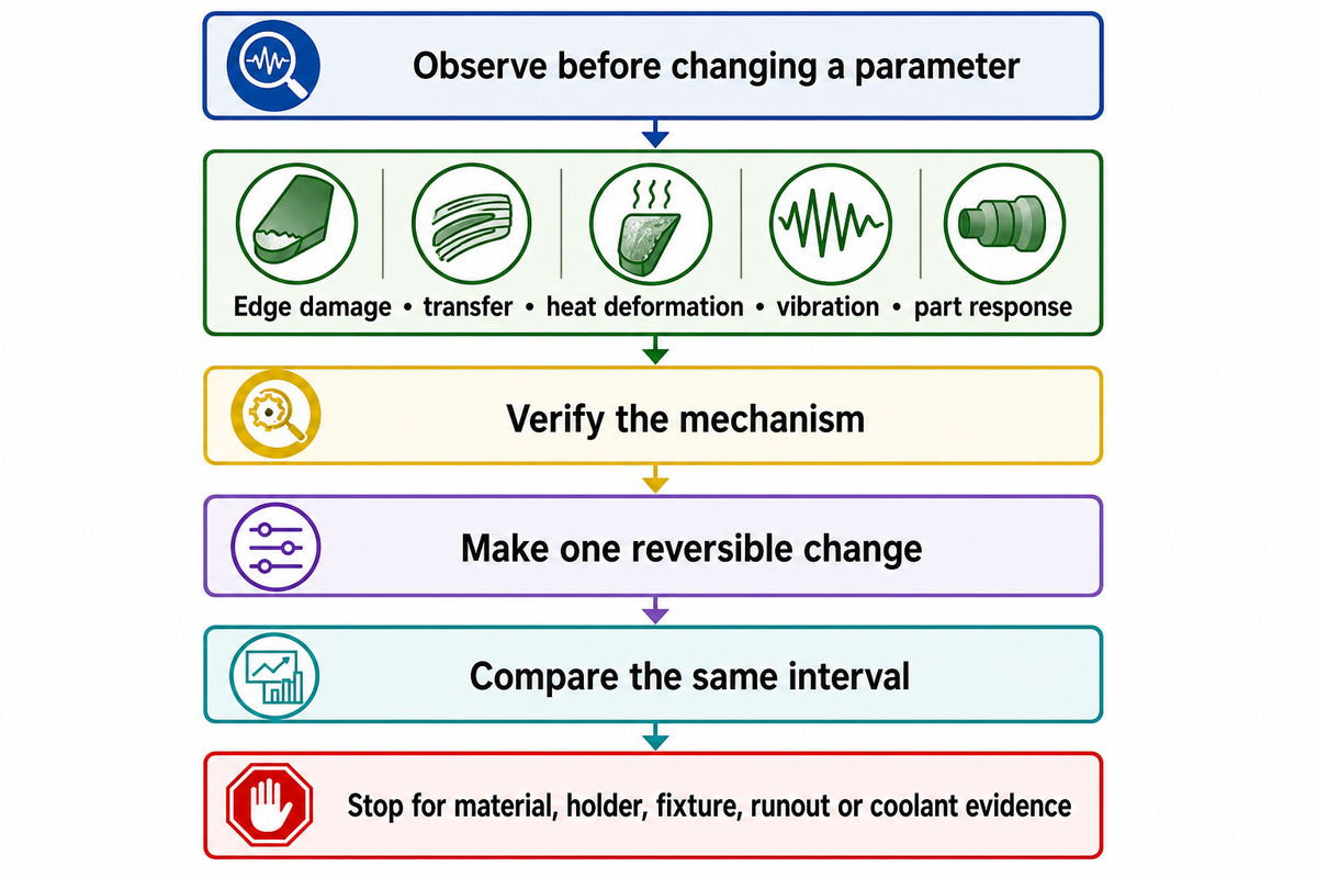
The Signal-Based Tool-Wear Decision Tree begins with observation, not a parameter change. Group evidence into edge damage, transfer, heat deformation, vibration, and part response. Verify the mechanism, make one reversible change, and compare the same interval; for chatter, NIST’s tool-length stability study shows that chatter-free chip width depends on both spindle speed and tool overhang. Change tools only at a defined wear limit; stop tuning when evidence points to material, holder, fixture, runout, or coolant.
| Observed type | Likely mechanism | Verify first | Reversible change | Avoid |
|---|---|---|---|---|
| Depth-line notch | Hard boundary/oxidation | Position, entry | Shift engagement | Same notch line |
| Random chipping | Impact/instability | Runout, fixture | Shorten loop | Speed first |
| Built-up edge | Adhesion | Chip, transfer | Restore chip formation | Rubbing feed |
| Flank wear | Abrasion/diffusion | Wear rate | One approved change | Run to fracture |
| Plastic deformation | Heat/load | Edge, coolant | Correct delivery | Blind feed change |
| Chatter marks | Instability | Frequency, overhang | Test stable band | Finish-only fix |
| Burr growth | Wear/weak exit | Trend, edge | Defined tool change | Hide by deburring |
| Chip packing | Poor evacuation | Flute, coolant | Clear path | Longer blind cut |
| Dimensional drift | Heat/wear | Warm-up, edge | Separate corrections | One masking offset |
- Photograph at fixed intervals
- Keep one feature and inspection method
- Record chip, load, finish, and size
- Runout or holder damage appears
- Coolant misses the edge
- Material or fixture control is uncertain
Evidence boundary: one shop case changed geometry, 38 to 60 sfm, and depth of cut from 0.075 to 0.15 in. Multiple changes make it system evidence, not a universal setting.
The Evidence Ladder for Real Inconel Capability
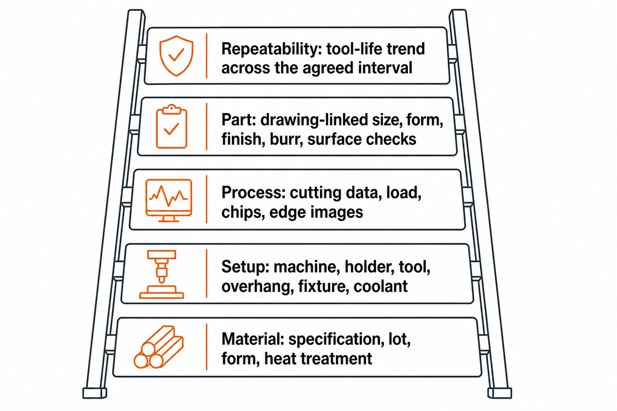
Precision engineering for Inconel requires linked records, not a claim that a shop cuts hard metals. For aerospace applications, aerospace Inconel buyers should request material identity, process data, tool-life progression, monitored signals, drawing-linked inspection, and repeatability. A certificate and a fresh-tool demonstration answer different questions.
- Material: specification, lot, form, heat treatment.
- Setup: machine, holder, tool, overhang, fixture, coolant.
- Process: cutting data, load, chips, edge images.
- Part: drawing-linked size, form, finish, burr, surface checks.
- Repeatability: tool-life trend across the agreed interval.
Paraphrase: NIST’s machining program links integrated measurement, physics-based models, and artificial intelligence to real-time monitoring of machines and manufacturing processes.
This NIST description explains process monitoring, not an Inconel threshold. For aerospace work, SAE AS9102C frames first-article records. Approval still doesn’t prove an indefinite tool-life window; add sustained records and requalification triggers.
No private Inconel production metric was supplied for this guide. Inconel is widely used in aerospace. For a specific job, compare the available records to the real feature and acceptance plan.
Evidence boundary: one face-turning study connected surface-integrity measurements with fatigue testing at 450 °C. Dimensional inspection alone may not be sufficient for critical parts; however, that study can’t certify another shop, machine, or turbine component.
Frequently Asked Questions
Is Inconel hard to machine?
Yes, it can be machined if the process is controlled. Low thermal conductivity, retained hot strength, work hardening, chemical affinity, and hard phases can concentrate load at the cutting edge. Rigid workholding, suitable sharp tooling, positive chip formation, controlled engagement, coolant delivery, and early wear inspection matter more than slowing every parameter.
What is the best end mill for machining Inconel?
There’s no ‘best’ end mill for every Inconel cut. A tough fine-grain carbide end mill with an application-appropriate coating and free-cutting geometry is a practical baseline. Choose flute count, helix, diameter, corner preparation, coolant delivery, and overhang for the pocket, radial engagement, material condition, and machine stiffness. Ceramic can be considered for a stable process that has been qualified.
Why is Inconel 718 difficult to machine?
Inconel 718 retains strength at cutting temperature, conducts heat poorly, work-hardens, and may contain strengthening precipitates and hard phases that increase edge loading. Supplied condition matters: aged material can cut differently from solution-treated stock. The specification, heat treatment, and product form must be confirmed before selecting toolmaker data or comparing tool life.
Can Inconel be milled?
Yes. When shops mill Inconel, rigid workholding with controlled engagement and adequate tooling, reliable chip evacuation, and no rubbing or dwelling can be beneficial. The approach depends on a number of factors such as grade, heat treatment, cutter, feature, coolant delivery, overhang, and machine dynamics. Validate the process for the actual conditions before starting production.
What cutting speeds and feeds are recommended for Inconel?
No universal speed and feed is safe. Work with the data for the alloy group and grade as provided by current toolmaker data. For each operation, note the type of engagement, condition and coolant. Convert to actual diameter and inspect the load, chip, sound, finish, and wear during a controlled cut, changing only one variable at a time.
Build a Process Window You Can Defend
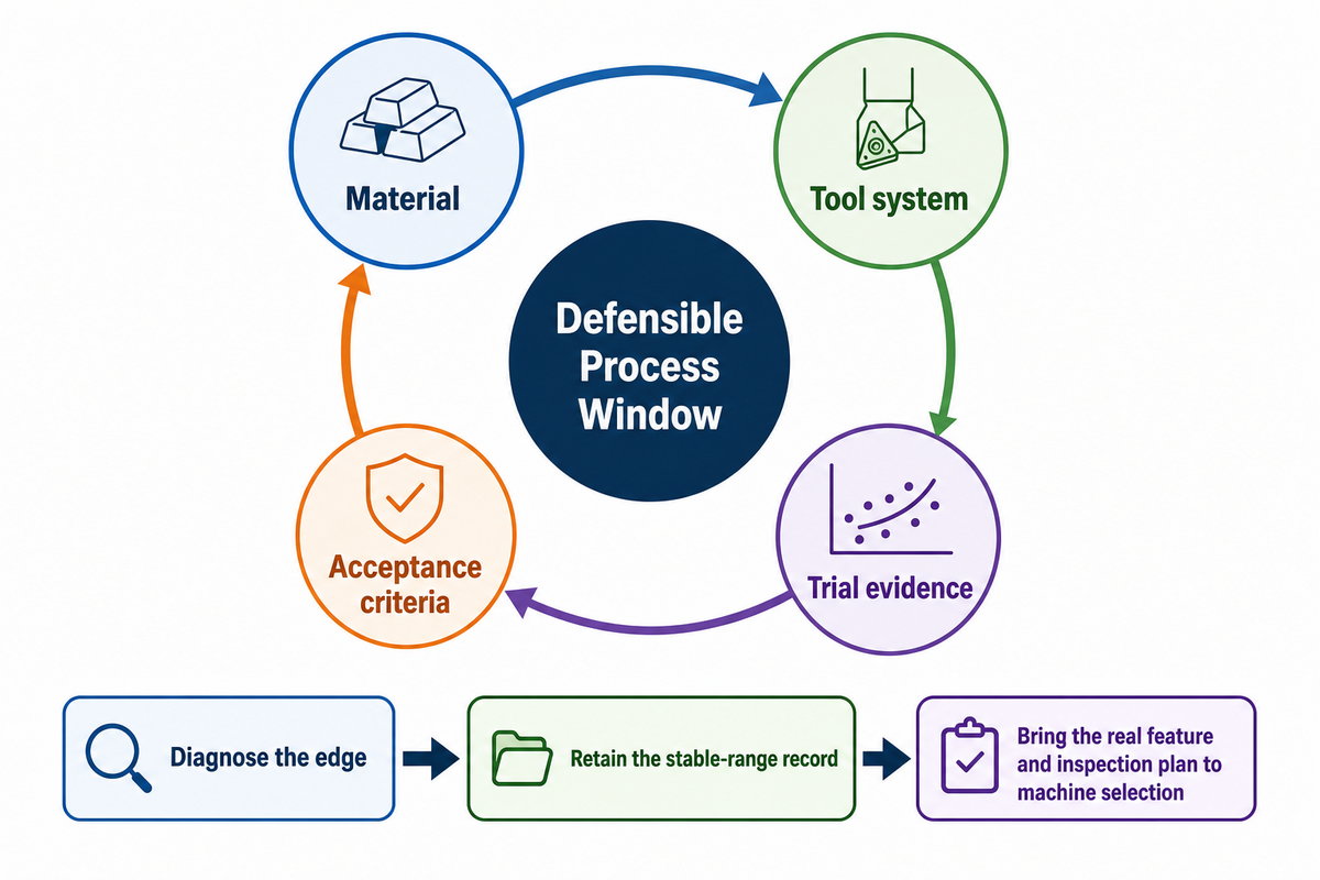
The machining of Inconel is controlled work. A defensible process window matches material, tool system, trial evidence, and acceptance criteria for Inconel components. Keep these machining challenges and solutions inside a fixed process boundary: diagnose the edge, retain the stable-range record, and bring the feature, condition, tooling, coolant, and inspection plan to machine selection.
About This Guide
Author: Karry. This guide doesn’t replace toolmaker data, a material certificate, risk review, or controlled trial.
References & Sources
- Inconel alloy review International Journal of Thermofluids
- Inconel 718 material-state study PubMed Central
- Alloy 625 aging ISIJ International
- Sandvik Coromant application article on machining nickel alloys Aerospace Manufacturing and Design
- Inconel turning study Mechanics & Industry
- Tool-length stability surfaces NIST
- ISO 230-3:2020 ISO
- Machining program NIST
- AS9102C SAE International
- Surface integrity and fatigue Mondragon University

![Machining Inconel & Nickel Superalloys [Practical Guide]](https://antishilathe.com/wp-content/uploads/2026/10/machining-inconel-featured.png)