




Standard machining tolerances are drawing rules, not a single number that every machine shop can promise. This guide shows how to read ISO 2768 size bands, separate size from geometry, and send a tolerance requirement that a supplier can quote and inspect consistently.
Request a “standard machining tolerance” from three shops and you will likely receive three different answers. One may quote a service default such as ±0.005 in; another may apply an ISO 2768 class; a third may ask for the released drawing before it gives a number. A machined part needs a dimensional tolerance and a stated tolerance range, not an imprecise standard. Defaults are to be expected of a service and stated conditions. An ISO class is associated with a drawing note. A feature-specific limit belongs to the function of that feature.
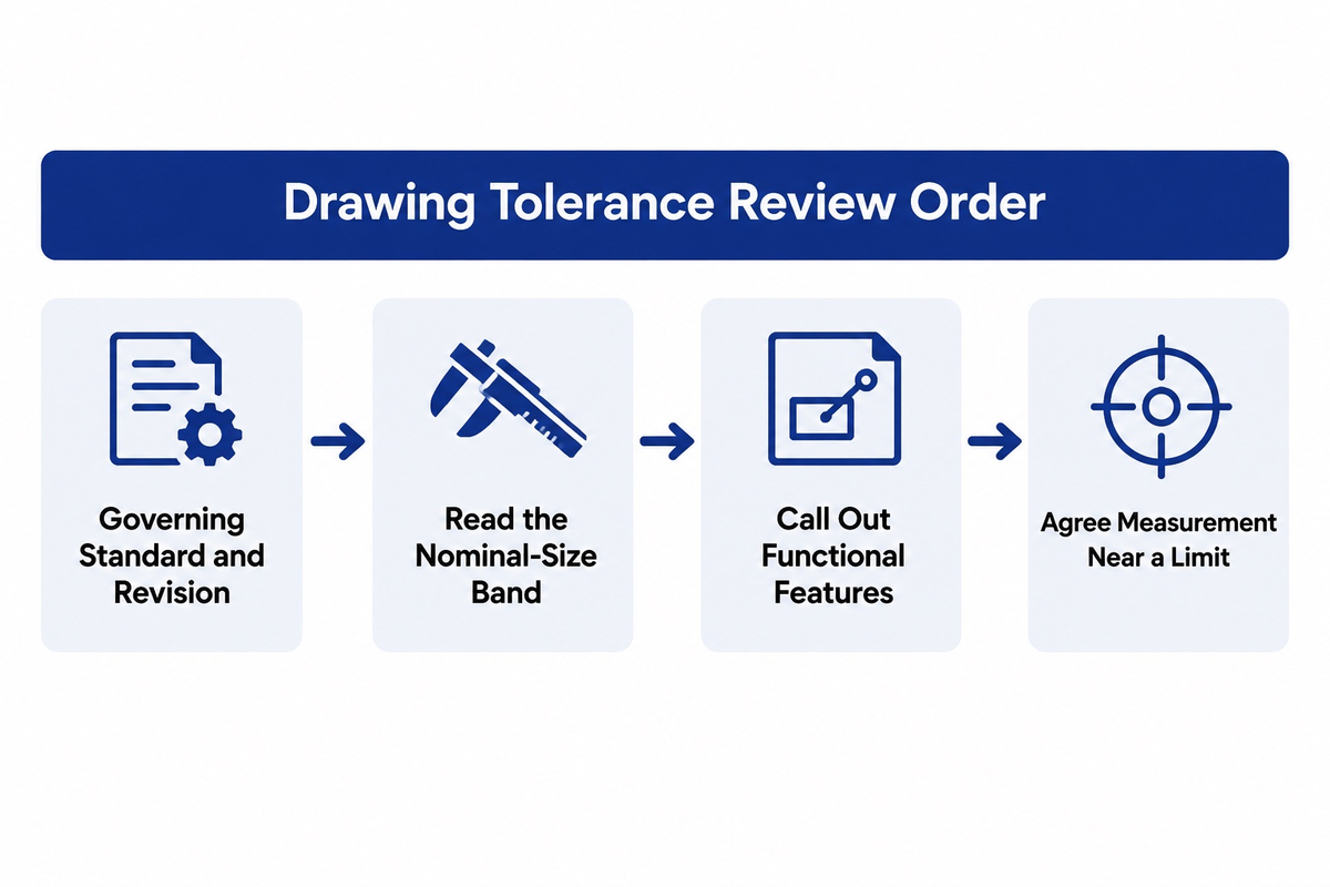
Use this order when you review an engineering drawing: identify the governing tolerance standards and revision, and read the correct nominal-size band. The drawing specifies an acceptable range that may be different. For a given functional dimension, determine the maximum/minimum size, form, orientation, and position, and agree upon how the result will be measured near a limit.
Standard machining tolerances at a glance
What is a normal machining tolerance?
A tolerance is the permitted variation around a nominal dimension. In a simple bilateral example, a 25.00 mm dimension with ±0.10 mm has a lower limit of 24.90 mm, an upper limit of 25.10 mm, and a total tolerance width of 0.20 mm. The +/- values are half-widths and are different from the total range.
That difference applies for every standard tolerance and tolerance class. Tolerance grades describe a band, while a tolerance value on a drawing shows allowable deviation for one machined part. That way, a manufacturer can choose a process without getting confused between a nominal dimension and an acceptance limit.
An engineering tolerance should be achievable for the stated process, and a manufacturing tolerance should be tied to the feature’s job. When you specify tolerances, name the tolerance requirements that matter and leave usual dimensions to the agreed general note.
Do not treat ±0.005 in as an industry-wide promise. Protolabs lists ±0.005 in (±0.127 mm) for one factory service when a part has no technical drawing, while its network row points to ISO 2768-1 classes for different material routes. That is useful evidence of a service policy, not a universal CNC machining tolerance. Your supplier may use another default, and your released drawing may override it.
Regarding equipment, a buyer can check our CNC lathe range, milling equipment and the relevant boring machine category. Those pages establish product scope, they do not replace a tolerance review for your part.
Drawing rule: write the standard, class, units, and revision in the drawing or enquiry. Use an individual callout for a feature whose function is tighter than the general note.
ISO 2768 tolerance chart: choose the size interval
The current ISO 2768-1:1989 covers general linear and angular dimensions without individual tolerance indications in four classes: fine (f), medium (m), coarse (c), and very coarse (v). Its public status page still lists the 1989 edition as published and current after its 2022 review. The same page points to a successor, ISO 2768 Edition 2, which the International Organization for Standardization currently marks as under publication at stage 60.00. As checked on 27 October 2026, that successor is not yet treated as a published replacement.
Table 1 in the original document provides nominal size bands. The table below, taken from a copy of the 1989 document, serves as an aid for interpretation; it is not a substitute in lieu of the standard, contract drawings, or other authorized documents.
| Basic size range | f | m | c | v |
|---|---|---|---|---|
| 0.5 up to 3 | ±0.05 | ±0.1 | ±0.2 | — |
| over 3 up to 6 | ±0.05 | ±0.1 | ±0.3 | ±0.5 |
| over 6 up to 30 | ±0.1 | ±0.2 | ±0.5 | ±1.0 |
| over 30 up to 120 | ±0.15 | ±0.3 | ±0.8 | ±1.5 |
| over 120 up to 400 | ±0.2 | ±0.5 | ±1.2 | ±2.5 |
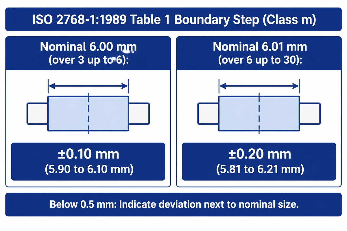
Pay attention to the word over. Under the table’s boundary convention, exactly 6.00 mm remains in the “over 3 up to 6” row. With class m, that gives ±0.10 mm, or 5.90–6.10 mm. A 6.01 mm feature moves to the “over 6 up to 30” row and class m becomes ±0.20 mm, or 5.81–6.21 mm. This is a calculation from the stated intervals, not a new tolerance recommendation.
According to the 1989 document, while selecting the class to apply, give consideration to the customary workshop accuracy for the dimensions without a tolerance indication. These general tolerances do not apply to dimensions covered by other general-tolerance standards, auxiliary dimensions in brackets, or theoretically exact dimensions in rectangular frames. For a dimension below 0.5 mm, the document says to indicate the deviation next to the nominal size rather than relying on the first table row.
General, unilateral and geometric tolerances
Use bilateral tolerances when variance in both directions is allowed. Use unilateral tolerances when deviation is allowed on one side of the nominal size, for example when a clearance is allowed to increase but not decrease, or when a stock dimension is allowed to decrease but not increase. Limit dimensions write the two defined boundaries directly. All three describe size.
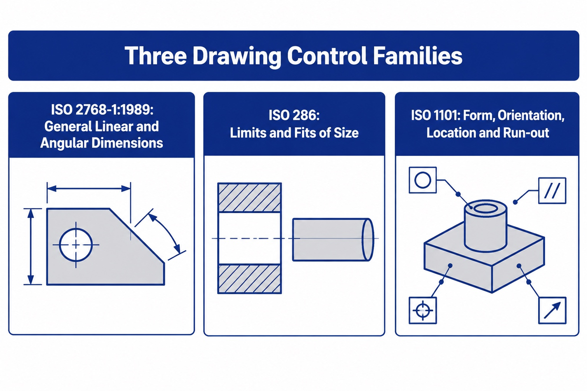
Size does not automatically control form or location. A bore can be within its diameter limits and still be out of round, angled, or displaced from its datum. The ISO catalogue separates the ISO 286 limits-and-fits system from ISO 1101 geometrical tolerancing for form, orientation, location, and run-out. That separation is the practical reason to put a datum and a position or perpendicularity control on a drawing when assembly depends on them.
When reviewing drawings, use geometric dimensioning and tolerancing (GD&T) to specify geometric requirements. A linear dimension is not interchangeable with straightness and flatness, symmetry, parallelism, or runout. A chamfer and an external radius are distinct features if called out in the drawing or general note.
General tolerance requirements cover an external radius or chamfer height if the standard being applied allows for it. It does not remove the requirement to specify the tolerance for a functional face, bore or datum feature.
| Functional concern | Useful drawing control | What to inspect |
|---|---|---|
| Will the part fit? | Size limit, fit designation, or bilateral/unilateral size | Actual size and mating part limits |
| Will the face seal? | Size plus surface and form requirements | Flatness, finish, and size under the agreed method |
| Will the hole locate the assembly? | Position relative to named datums | Location, orientation, and size in the datum reference frame |
| Will the shaft rotate smoothly? | Size plus run-out or coaxial relationship | Size, axis, and rotational variation |
| Feature or requirement | Primary risk | Evidence to request |
|---|---|---|
| Overall length | Envelope mismatch | Limit measurement and drawing revision |
| External diameter | Fit or clearance | Micrometer method and temperature condition |
| Internal bore | Size and lobe variation | Bore-gauge or CMM method with master status |
| Locating hole | Position error | Datum frame and position report |
| Mounting face | Flatness or seating | Support condition and flatness result |
| Rotating shaft | Run-out or concentricity | Rotation method and datum axis |
| Thin wall | Clamp release movement | Clamped versus released readings |
| Threaded feature | Assembly engagement | Gauge type and thread standard |
| Surface finish | Seal or friction change | Instrument, direction, and sampling locations |
For a detailed look-up of hole fits, see ANTISHICNC’s hole tolerance chart. That chart and this document serve distinct purposes. This document is a reference on how to choose and communicate the appropriate tolerance system. The tolerance chart is a fit reference.
CNC machining tolerance depends on the process
What tolerance can a CNC mill hold?
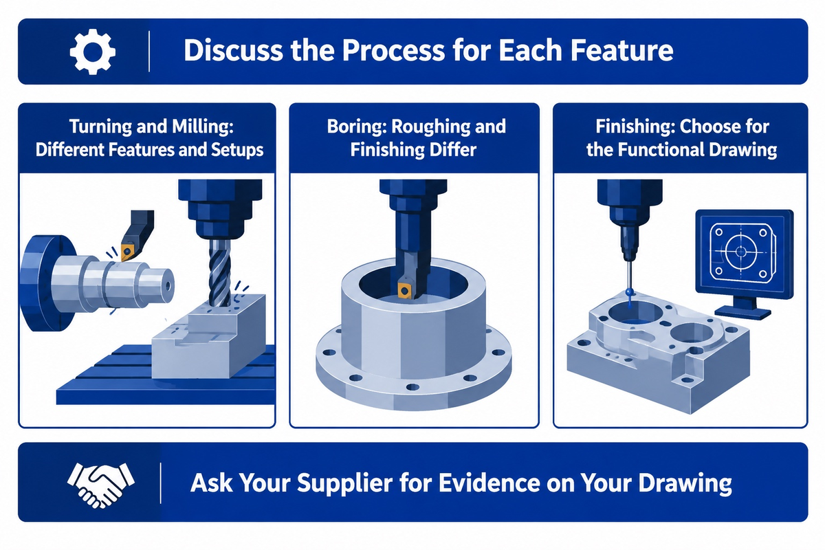
Turning, milling, drilling, reaming, boring, and grinding do not control the same features in the same way. A turning operation can control the diameter and shoulder of a feature on a part. Milling can control a face or a datum in a different setup. Drilling creates a hole, but a finishing operation may be required to achieve the final size and surface. Boring enlarges a hole, and like a drilling operation, requires consideration for tolerance, surface finish, position, straightness, depth and workholding.
Therefore, interpret a CNC milling, CNC turning or CNC machining service default as process context. A CNC machined part still needs a functional drawing. The supplier decides on standard CNC machining or precision CNC work and/or a second finishing operation.
A useful level of precision may come from a CNC machining center, but machine capability is still conditional on many factors, such as setup, tool path, work holding, material, and inspection. When comparing processes, do not just list a series of tolerance labels copied from a brochure.
Sandvik Coromant’s boring guide distinguishes roughing from finishing and tells the reader to check the hole, component, and machine as one system. Its IT6–IT8 finishing guidance is the supplier’s application guidance; it is not a guarantee for every material, diameter, or machine. Use that kind of source to frame a process discussion, then ask your supplier for evidence on your drawing.
Other published defaults vary by service. A service table may quote a default for parts without drawings and a different path for parts with drawings. Therefore, a purchase order should contain the released drawing, not just a phrase like “standard CNC tolerance.”
Material, size and setup change the result
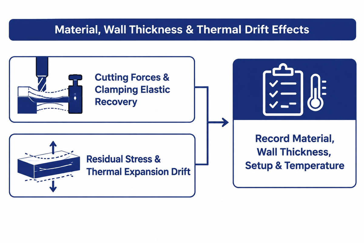
Thin walls illustrate why a tolerance can’t be separated from the process. A current thin wall machining guide describes the mechanics of cutting forces and clamping pressure, and how residual stresses are redistributed. Failure modes include chatter, taper, and thickness variation due to push off and spring back. An elastic wall can show changes in measured flatness and perpendicularity even if it was measured within tolerance while being fixtured.
There’s more to talking about temperature than Measurement Uncertainty Analysis. The National Institute of Standards and Technology’s dimensional-metrology abstract models a steel test gauge measured with a machine and master gauge and assesses uncertainties caused by thermal expansion. It suggests controlling the measurement condition and notes that a universal material coefficient for every job is not provided. Take into consideration material, feature length, wall thickness, stock condition, setup, coolant practice, and measurement temperature when a feature is thermally sensitive.
Measure the tolerance before accepting the part
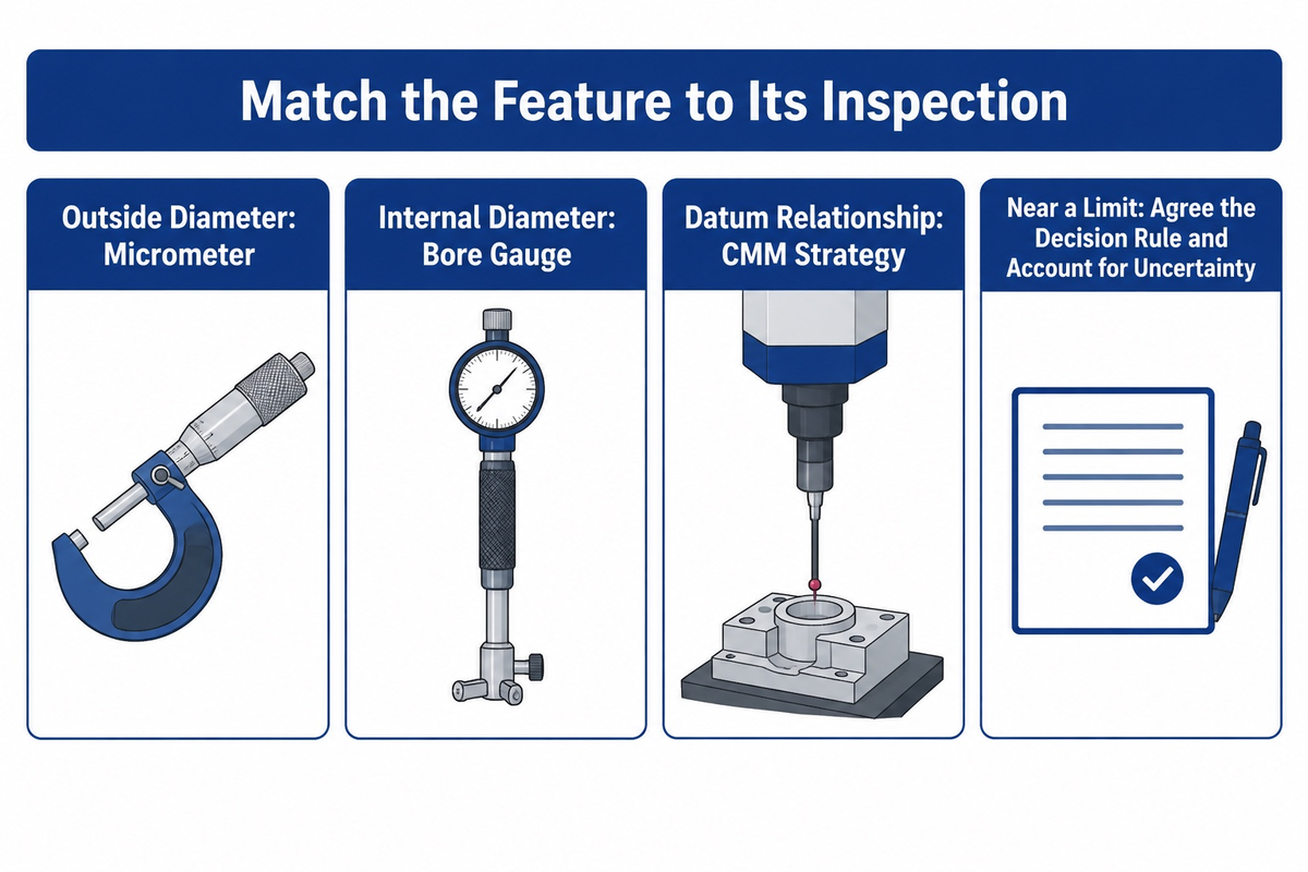
A measurement result near a specification limit requires a decision rule that is agreed to by all affected parties. ISO 14253-1:2017 addresses conformity and nonconformity decisions when a measured value is close to a specification limit and measurement uncertainty matters. The public abstract does not provide a universal machining allowance or a one-size-fits-all gauge ratio.
A micrometer is a good instrument for measuring outside diameter. For inside diameter, a bore gauge is suitable. However, a properly used bore gauge can also reveal lobing and/or dimensional variation behavior. A coordinate measuring machine can also be used to define a datum relationship. However, the program, probing strategy, temperature, and uncertainty are also important. Modern shop floor systems can return inspection results to a machine; a Renishaw Equator-X & AGILITY announcement describes this capability. Not all machines can have a similar feature as that of Equator-X & AGILITY.
Do not generalize one “first-off” result as an absolute capability number. The process-capability reference from NIST defines capability relative to a process that is in statistical control and specification limits and warns that capability indices are distribution dependent and rely on sufficient independent data. Consider the feature condition and state of the sample (as defined in the measurement plan) before interpreting a capability number.
“Process capability compares the output of an in-control process to the specification limits by using capability indices.”
— NIST/SEMATECH e-Handbook of Statistical Methods, Process Capability
Quote standard and custom machining tolerances
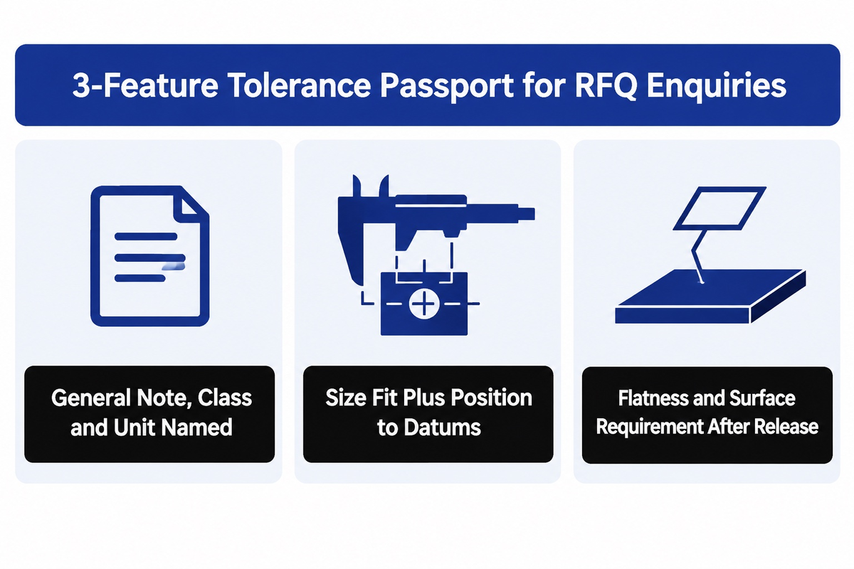
Use the “3-Feature Tolerance Passport” when sending an enquiry. It highlights the features that impact price and acceptance.
Consider the specific tolerance, tolerance limits, allowable deviation, material hardness, fixturing and stack-up assembly when making your decision. This helps specify the machinist requirement and enables the buyer to discuss machining costs with the understanding that not every high-precision feature will require the same machining process.
Use “international standard” only when the drawing names the document and edition. When there is a proposed similar standard, require the supplier to state what is different before the quote becomes a production requirement. The same rule applies for surface treatment and for any change in inspection defined by aerospace or other industry-specific requirements.
| Feature | Function | Drawing control | Process/inspection question |
|---|---|---|---|
| Housing length 120.00 mm | Non-mating envelope | General note, class and unit named | Which class is applied to the 30–120 mm band? |
| Locating bore 20.00 mm | Mating pin and location | Size fit plus position to datums | Which finishing process and bore measurement method? |
| Mounting face | Assembly seating | Flatness and surface requirement | How is the face supported and inspected after release? |
Put the material and condition, quantity, finish sequence, datum scheme, drawing revision, and inspection-report requirement beside this passport. General tolerances cover eligible uncalled dimensions; they do not erase an individual critical callout. Clause 6 of ISO 2768-1:1989 (1989 document text) also carries a qualification: unless otherwise stated, exceeding a general tolerance does not automatically require rejection when the workpiece still functions. Treat that historical clause as a rule to read with the current contract and function, never as permission to ignore a separately specified bore, seal, or datum.
Compare machines using a representative part
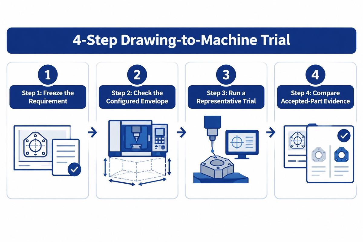
Use the 4-Step Drawing-to-Machine Trial to compare suppliers:
Step 1 – Freeze the Requirement
Issue one drawing revision, material, quantity, datums, tolerances, and inspection method to each supplier.
Step 2 – Check the configured envelope. Check swing, effective turning length, spindle bore, bar passage, tool arrangement and optional draw tube for the exact configuration.
Step 3 – Run a representative trial. Use the same feature geometry and record the setups, tools, stock conditions, temperatures and consecutive measurements.
Step 4 – Compare accepted-part evidence. Separate results from repeat measurements, first-off conformity and axis-tests, as well as results pertaining to long-term capability. Do not combine them into a single “machine accuracy” number.
ANTISHICNC’s public CK6130 technical document lists a 300 mm swing over bed, 230 mm maximum turning length, 48 mm spindle through hole, 45 mm bar diameter, and a 0.001 mm minimum setting unit. The CK6140 document lists a 400 mm swing and, for the 550 configuration, a 420/300 mm maximum turning length depending on the six- or eight-position tool arrangement. It lists 48/82 mm spindle-bore configurations and 40/65 mm bar-diameter configurations with paired speed values. Those are catalogue configuration facts. The 0.001 mm setting unit is not a finished-part tolerance, and none of these documents is a customer trial or an independent certification.
Per the ISO catalogue, ISO 230-2:2014 is a test code to assess the accuracy and repeatability of positioning numerically controlled axes. This would be a different evidence object from a finished part which is compared against your released drawing. Ask the supplier to explain which object is represented by each test result.
Put the standard edition into the drawing and enquiry
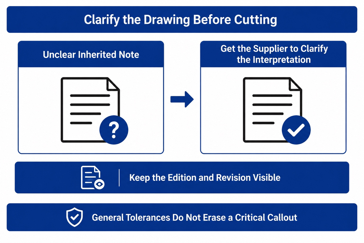
Keep the edition and revision visible. ISO 2768-2:1989 is marked withdrawn on the International Organization for Standardization page, with ISO 22081:2021 listed as its new version. ISO 22081’s public abstract describes rules for general geometrical and general size specifications; it is not a numeric replacement table for the linear f/m/c/v values in ISO 2768-1. Meanwhile, Edition 2 of ISO 2768 is under publication and says it will replace ISO 2768-1:1989. These lifecycle facts can change, so date your drawing review and obtain the text required by your contract.
When an inherited title-block note is unclear, get the supplier to clarify their interpretation before you cut the material. A one-line interpretation is cheaper than having an argument over whether a size row, geometric class, or a measurement rule was intended.
Frequently asked questions
What is the ISO standard for machining tolerances?
This standard, ISO 2768-1:1989, gives general tolerances for linear and angular dimensions without individual indications in four classes. ISO 286 addresses limits and fits, while geometric controls use their own specifications. Put the chosen standard, edition, class, and units on the drawing. Give fit-critical and datum-critical features individual callouts instead of assuming a general note controls every requirement.
Is 0.005 inch a tight tolerance?
It depends on the feature, process, and inspection method. ±0.005 in equals ±0.127 mm, and the total width is 0.010 in. Protolabs publishes that value for one service default, but a service default is not a universal standard. State whether your number is bilateral, unilateral, or a limit, and ask the supplier to confirm the process and measurement conditions.
Is 0.01 mm a tight machining tolerance?
It can be demanding, particularly on a long, thin, hot, or difficult-to-measure feature. First check whether 0.01 mm is total width or a plus-or-minus value. Then identify the feature’s function, datum relationship, finishing operation, and acceptance method. Machine setting resolution alone does not prove that a production part will hold the drawing limit.
Is 0.05 mm a good tolerance?
Only if it retains the feature’s function across the complete process can it be demonstrated. More restrictive numbers are not always better.
Can a part have zero tolerance?
Typically, manufactured parts exhibit some level of total variation. The zero in a notational system may be used to represent a zone boundary, like a zero lower deviation in an H hole. Fit still relies on both mating limits, and uncertainty remains with inspection. Separate nominal dimensions, allowed limits, geometric requirements, and measurement rules. If the drawing specifies a function fit, then specify limits, name fits, or use other methods rather than adding excessive decimals to make the number look “exact”.
References & Sources
- ISO 2768-1:1989 public scope and lifecycle.
- ISO 2768 Edition 2 publication status as checked 27 October 2026.
- ISO 2768-2:1989 withdrawal record and ISO 22081:2021 public scope.
- ISO 14253-1:2017 conformity decisions and measurement uncertainty.
- ISO 286 and ISO 1101 catalogue for limits, fits, and geometrical tolerancing, and ISO 230-2:2014 catalogue for numerically controlled axis positioning tests.
- Refer to the National Institute of Standards and Technology process capability reference.
- National Institute of Standards and Technology dimensional-metrology thermal-expansion publication.
- Sandvik Coromant boring application guide.
- ANTISHICNC CK6130 technical document and CK6140 technical document.