




Updated October 2026
Parts like a shaft, brake disc or an electric motor housing can all require automotive CNC machining, but create very different equipment needs. Engineers using CNC machining to produce parts begin with the finished drawing, showing which surfaces carry the function, how the blank reaches those surfaces, and how the finished part is released.
Automotive CNC machining uses programmed cutting operations to create or finish features of vehicle parts. Turning is used to make rotational features and milling is used to create faces, pockets and other patterns. Machine choice is dependent on the blank, workholding and inspection requirements.
- Part family: shaft, disc, housing, gear blank or prismatic component.
- Physical fit: blank envelope, tool reach and the narrowest through-bar opening.
- Quality target: drawing limits, surface texture and the agreed release checks.
- Capacity target: accepted parts per shift, including loading and gauging.
- A cast or forged blank can still need substantial finish machining.
- A spindle opening and a usable bar diameter are separate dimensions.
- Faster cutting raises output only when cutting constrains the cell.
- Compare costs against released parts, with the same costs included in each route.
Where automotive CNC machining fits in the process chain
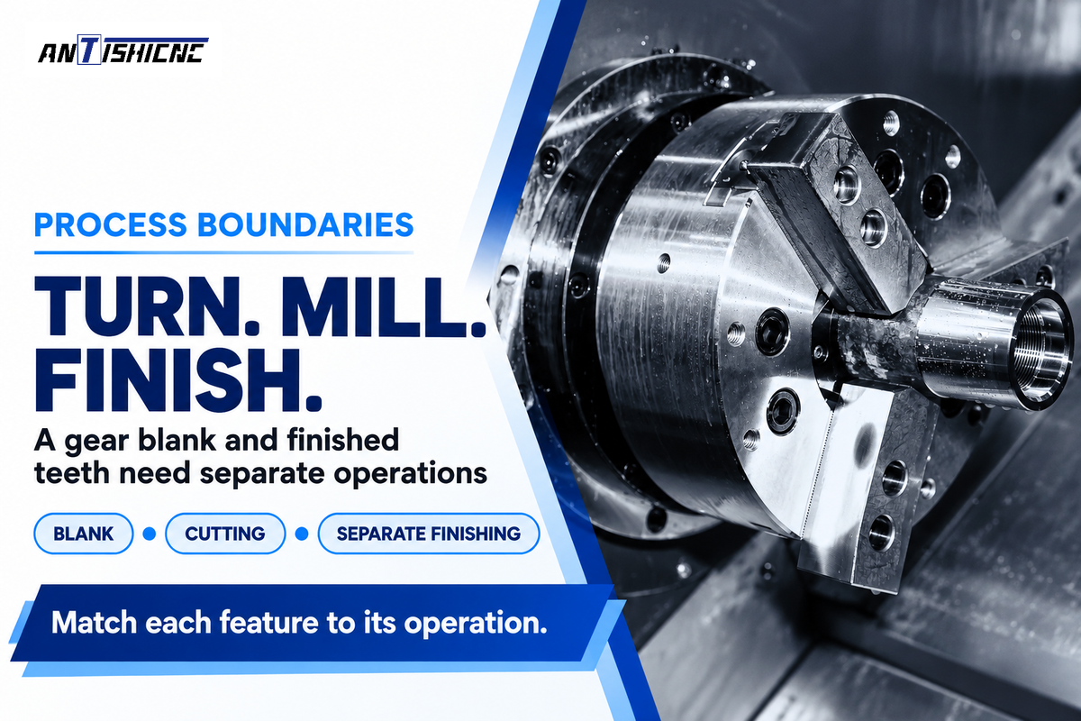
CNC machining for the automotive industry includes both creating a part from a piece of stock and finishing or creating features on a near net shape part. A useful process chain follows the blank through a series of operations. Assign each finished feature to an operation before choosing the machine that will perform it.
CNC machining involves different cutting motions. CNC technology enables stored toolpaths to repeat a job with workholding and tool condition controlled. As the Erie Institute of Technology turning guide explains, turning rotates the workpiece and milling rotates the cutter. A housing with faces and bearing bores therefore is a different task from a shaft with journals. The same CNC program can’t address differences in access and workholding.
6-Part Process Map
The 6-Part Process Map links a family of parts to their blank, cutting operations, finishing operations and inspection.
| Part family | Starting shape and cutting route | Separate operation to retain | Drawing characteristic to control |
|---|---|---|---|
| Shafts and pins | Bar or forged blank; turn journals, faces and grooves | Heat treatment and journal grinding when specified | Journal size, runout and shoulder relation |
| Brake discs | Cast blank; turn friction faces and locating features | Balancing and specified surface finishing | Face runout and thickness variation |
| Engine blocks and cylinder heads | Cast blank or development billet; mill faces, drill and bore | Honing, washing and leak testing where required | Bore geometry, deck relation and sealing faces |
| Transmission and motor housings | Cast blank or billet; mill mounting faces and bearing bores | Deburring, cleaning and leak checks for the design | Bearing-bore position and sealing-face geometry |
| Gear components | Forged or bar blank; turn bore, faces and outside diameter | Tooth generation, heat treatment and gear finishing | Tooth geometry as well as bore and face datums |
| Brackets and prototype interfaces | Plate, billet or near-net blank; mill pockets and holes | Coating or insert installation where specified | Hole pattern and mating-face position |
Distinctions in gearing are very evident. Turning creates the bore and faces of a gear blank. Generating teeth and finishing the tooth flanks require separate operations. The Reishauer gear-process monitoring application, published in 2022, focuses on the monitoring of the final finishing of pre-toothed workpieces. Keep that operation separate in your comparison of equipment. ANTISHICNC’s guide to CNC turning motion and operations has more information on the turned part of a route.
What products are made by CNC machining for the automotive industry?
CNC machining can produce shafts, pins, brake-disc features, engine-block bores, cylinder-head faces, transmission housings and motor housings. These automotive components are applications of CNC machining. Gear blanks and brackets also fit the process. Some components begin as castings or forgings, while development parts can start as billet; the required finished features determine the cutting and secondary operations.
Multiple applications in the automotive industry combine casting with cutting. A cylinder head illustrates the significance of the route. Mounting faces and bores can be produced using CNC machining while the casting supplies internal passages. A billet prototype shows how CNC machining is used to assess an accessible interface, but producing a similar external shape does not reproduce the casting’s internal features or its material history. These differences will appear in the route of processing, before comparing final part costs.
Materials and blanks: billet, castings or forgings?
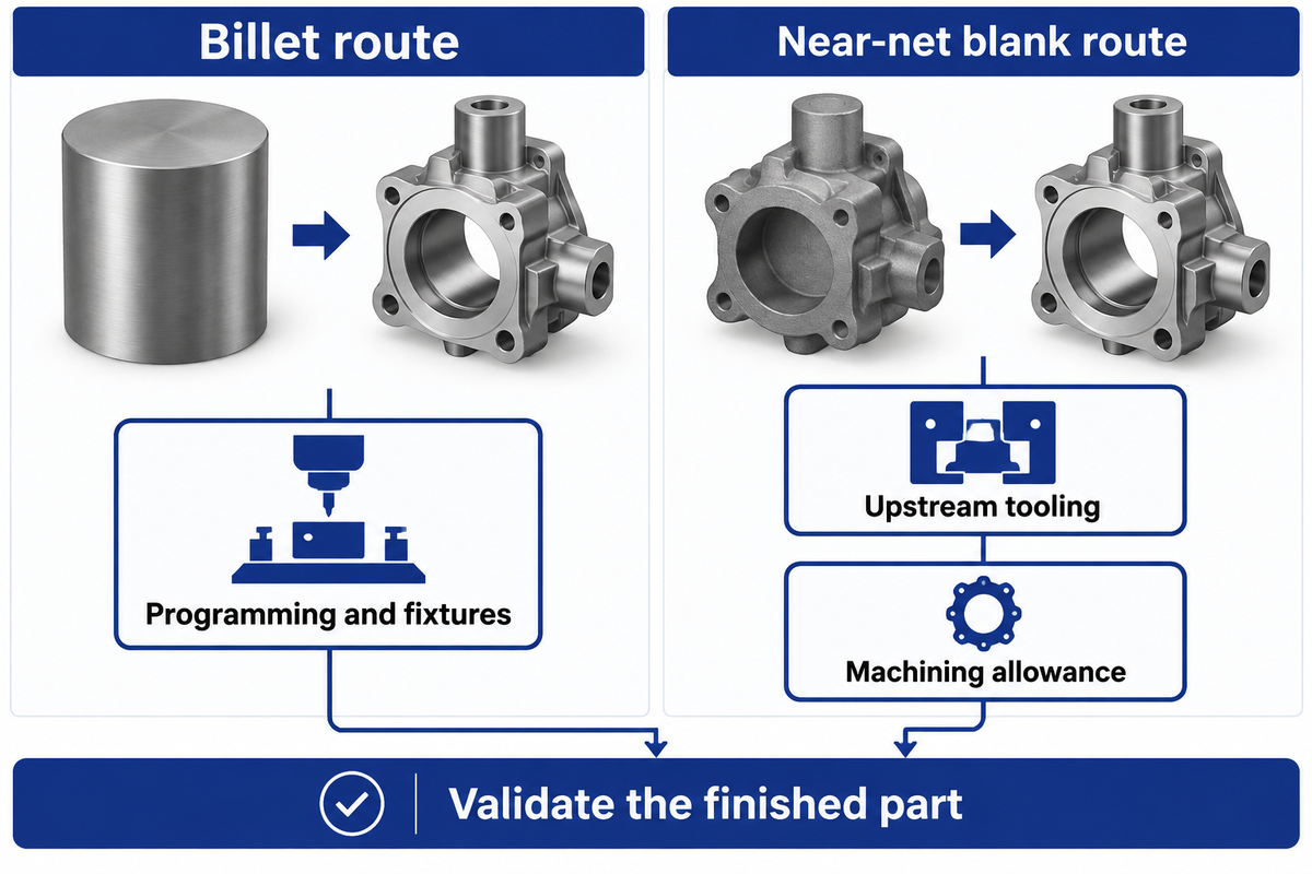
Consider the requirements of the part performance and the material specification to decide on the routes for an available blank. During development, CNC machining offers a billet route that can be changed through programming and fixtures. Traditional methods such as casting and forging change the amount of cutting and the upstream tooling commitment. Both routes require verification of the specified material condition and the finished part performance.
Materials for automotive CNC machining include, but aren’t limited to, cast iron, steels, aluminum alloys, and engineering plastics, in different automotive applications. However, this is only an initial filter. Automotive designers and engineers also need the alloy grade, heat treatment and product form. Changing an accessible contour shows how CNC machining allows design revisions while keeping that material specification fixed. A wrought grade cannot simply replace a cast grade because its name sounds familiar, and just because a part is machined doesn’t mean the whole part is qualified for its service load.
In a Practical Machinist discussion, the author states that the appearance of a part can make someone believe that a part was cast when, in fact, it may have been forged. The forum participants also connected machining allowance to wall thickness and core shape. The practical approach would be to first reconstruct the original material and routing before copying its visible outline when determining a replacement.
Zoroufi and Fatemi’s 2004 steering-knuckle research tested both material specimens and complete components. Its comparisons changed material as well as manufacturing route. Dimensional inspection and fatigue qualification address different questions, so a dimensional acceptance result can’t stand in for the required component-performance work.
- Revise accessible features through the program and workholding.
- Include removed stock and cutting time in the comparison.
- Retain material and component validation for the intended use.
- Include the blank supplier’s tooling and minimum-lot terms.
- Include locating surfaces, machining allowance and finish cuts.
- Retain material and component validation for the intended use.
How does the cost of CNC machining compare to other automotive part production methods?
Rather than evaluate the price of casting and forging, compare the price of finished accepted parts. For a billet route, CNC machining eliminates the need for a dedicated shape-forming die, but it still requires cutting tools, programs and fixtures. Near-net methods add upstream tooling and can reduce stock removal; lot size and design changes affect that tradeoff.
A 2020 open-die forging cost study explicitly excludes subsequent machining and heat treatment from its cost model. Consequently, it may not be directly applicable to the automotive industry. The study validated large oil-and-gas components; its prices and prediction errors are outside this automotive comparison. However, it provides some insights on the costs associated with various operations. For example, we should cost out all operations and incorporate them into the quote before CNC options are compared to traditional machining methods.
How to choose a CNC machine for car parts
Use a CNC lathe for rotational features and a machining center for prismatic features. Justify the use of additional axes or combined operations in the drawing if tool access and measured complete-part cycle times allow. In addition to the intended features, a machine tool must also fit the blank and fixture through the complete cutting path, loading and end supporting the workpiece.
| Machine class | Features it addresses | Purchase decision |
|---|---|---|
| 2-axis CNC lathe | Rotational outside diameters, bores, faces and threads | Start here for turned parts with tool access in X and Z. |
| Live-tool turning center | Turned features plus accessible milled flats and drilled holes | Specify driven tools and C-axis control; include Y-axis travel when the feature needs it. |
| Mill-turn with a second spindle | Two-ended parts and transfers between turning and milling | Compare transfer repeatability and complete-part cycle with separate machines. |
| 3-axis vertical machining center | Prismatic parts with accessible faces, holes and pockets | Use fixtures and planned reorientations for the required sides. |
| 4-axis horizontal machining center | Multiple sides of a housing around an indexed axis | Check pallet/fixture sweep, chip evacuation and loading access. |
| 5-axis machining center | Angled features and curved surfaces with changing tool orientation | Choose indexed or simultaneous motion from the toolpath and collision study. |
| Cylindrical or surface grinder | Specified hardened journals, flat faces and finish requirements | Retain grinding allowance and a suitable measurement method. |
| Gear cutting and finishing equipment | Tooth generation and tooth-flank finishing | Quote the tooth process separately from turning the gear blank. |
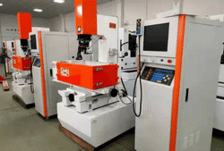
| Electrical discharge machining | Conductive tooling and features awkward for a rotating cutter | Compare electrode or wire access and the required finish route. |
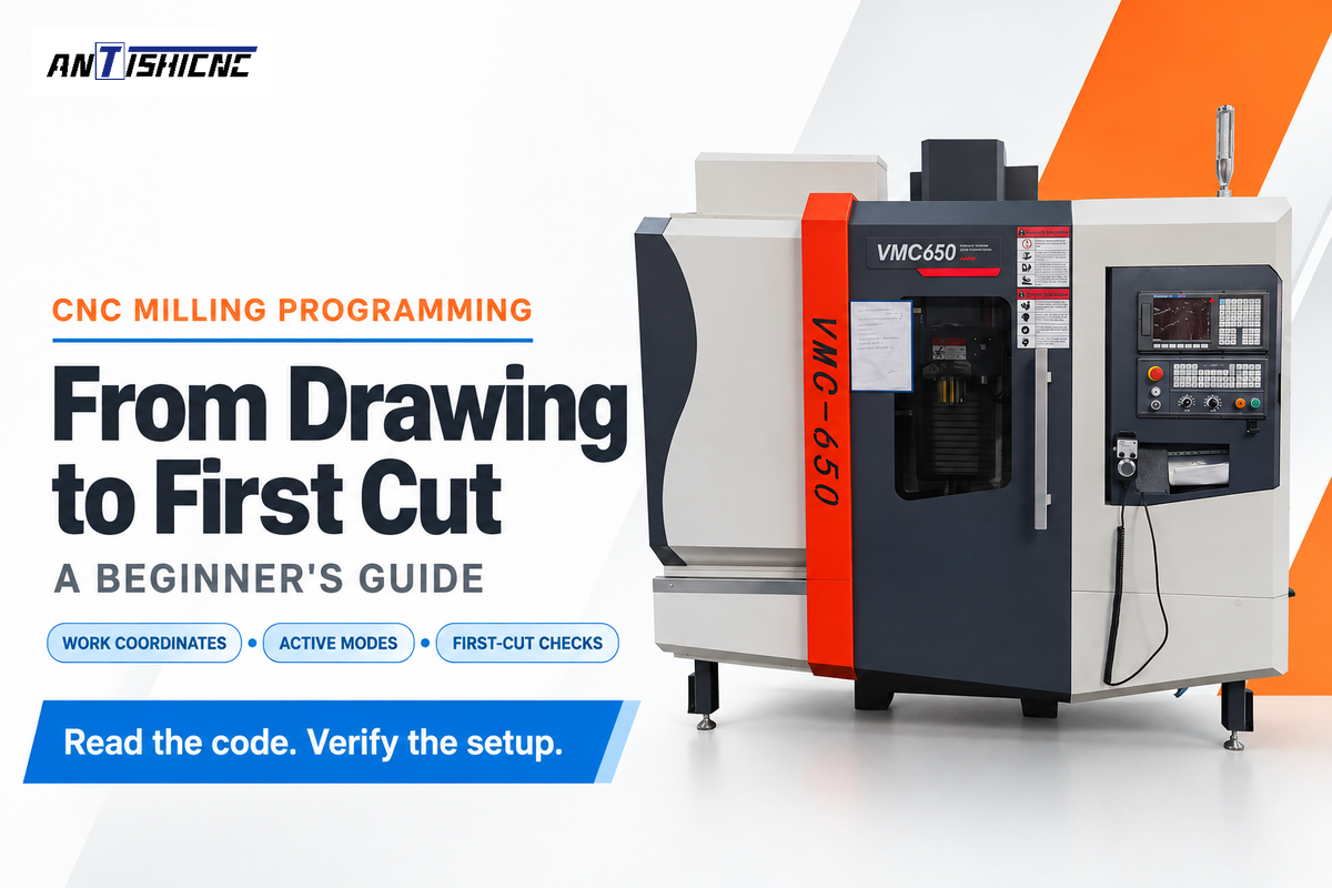
The versatility of CNC machining is mainly a function of the appropriateness of CNC machining capabilities to the job. For complex parts, CNC machines enable fewer reorientations through multi-axis machining centers, but additional motion also requires collision control and appropriate fixtures. For routing and milling, the VMC650 vertical machining center is in a different class compared to a lathe. Compare precision and efficiency across each drawing before treating the mill-turn as a replacement.
ANTISHICNC supplies CNC machine tools, including CNC lathes. The proposals include details to compare the two models. The figures shown are the supplier’s listed values for these proposals. CNC machines handle a blank in a physical work envelope, hence that envelope must be checked before cycle time. They depict machine dimensions and ratings; workholding and the selected build govern the cutting arrangement.
| Published parameter | CK6130 | 235 LANCEN | How to use it |
|---|---|---|---|
| Swing over bed | 300 mm | 460 mm | Screen the rotating envelope. |
| Slide clearance measure | 100 mm max. turning diameter over slide | 260 mm swing over cross slide | Check the actual fixture and tool envelope; these labels differ. |
| Distance between centers | 320 mm | 570 mm | Keep this separate from usable turning length. |
| Maximum turning length | 230 mm | 550 mm | Include chuck, tools and end-support access. |
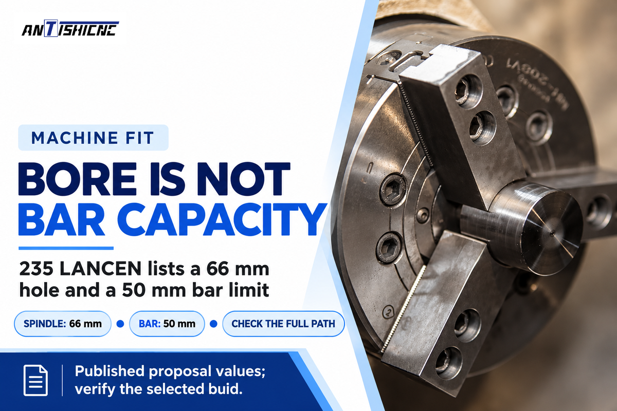
| Spindle through-hole | 48 mm | 66 mm | Check the full bar path. |
| Listed bar diameter | 45 mm | 50 mm | Use the bar rating rather than the spindle hole alone. |
| Hollow-chuck tie-rod opening | 40 mm, optional | 50 mm, hydraulic | The smaller opening can govern a through-bar job. |
| Spindle limit speed | 2,500 rpm | 3,500 rpm | Apply chuck and workpiece speed limits as well. |
| Main motor power | 4 kW | 11 kW | Compare the torque curve at the cutting speed. |
| Total listed power | 10 kW | 15 kW | Plan the electrical supply separately from spindle power. |
| X/Z rapid traverse | 6/10 m/min | 18/18 m/min | Rapid motion is not cutting feed or complete cycle time. |
| Net machine weight | 1,700 kg | About 2,600 kg | Include delivery, foundation and service access. |
The 235 LANCEN published machine build lists a 66 mm spindle hole alongside 50 mm bar and tie-rod openings. A 60 mm through-bar requirement therefore fails that listed bar-path screen, even though 60 mm is smaller than 66 mm. A separately held blank is a different work holding proposal and requires a different fixture set-up.
Consider a proposed 45 mm bar job on the CK6130. The listed bar diameter is 45 mm, while the optional hollow-chuck tie rod has a 40 mm opening. Selecting that draw tube blocks the proposed through-bar route. The buyer can evaluate other comparable workholding builds or a cut-blank loading route, prior to spending time on cycle estimates. A short-turned part also needs room for its jaws and cutting tools; bed swing alone will not resolve this.
A 50 mm bar limit and a 66 mm spindle hole define two interfaces on the 235 LANCEN. Screening the smaller opening first lets buyers avoid a purchase based on a nominal bore size. Complete the clearance check with chuck jaws, turret tools and end support in their working positions.
Precision, tolerances and inspection
Precision CNC machining requires a drawing based inspection plan for machining tolerances within the automotive industry and evidence that the process is stable. For a high precision requirement, separate instrument resolution, machine positioning, finished-part geometry and the rule used to release a measured part. A first-off sample helps prove the setup; sequential production data reveals drift and variation that an isolated sample cannot show.
NIST’s process-stability guidance places stability before capability analysis. Tool wear, clamping movement and changing temperature can affect results even while CNC machines operate with an unchanged program. At the control level, CNC machining provides repeatable commanded movements. The complete process includes the material and the measurement system.
“we cannot begin to talk about process capability until we have demonstrated stability in our process.”
NIST’s capability explanation separates Cp from Cpk: the latter accounts for an off-center process. Record production measurements in order, along with tool changes and operating conditions. A histogram can hide the sequence of a drifting process, while a single average can hide its spread.
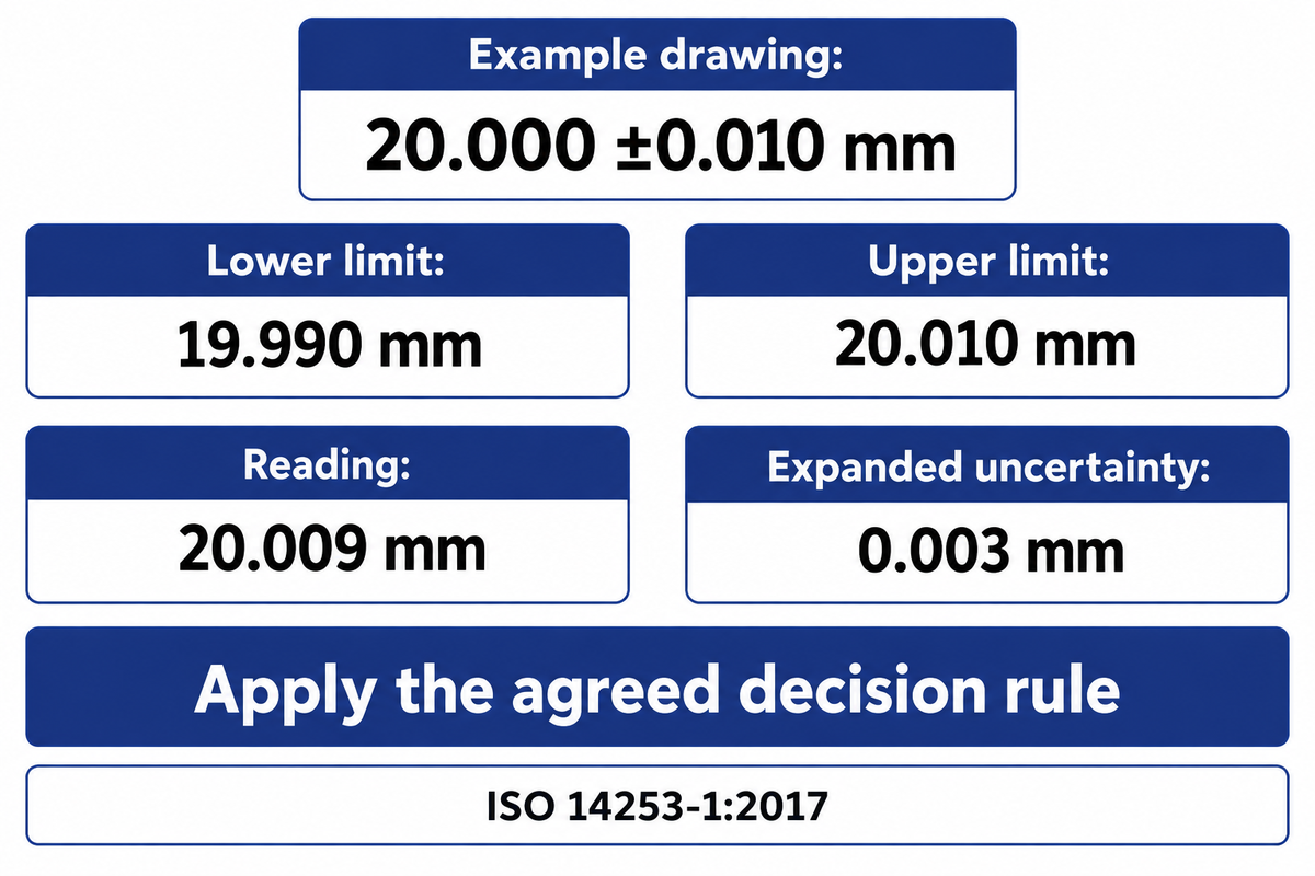
Example drawing: 20.000 ±0.010 mm. The specification extends from 19.990 to 20.010 mm, a 0.020 mm width. A reading of 20.009 mm with an expanded measurement uncertainty of 0.003 mm needs the agreed conformity decision rule. ISO 14253-1:2017 addresses such decisions, including measured values near specification limits while taking uncertainty into account.
Precision machining requires selection of a gauge for a characteristic. CNC machining allows for precise feature placement when the toolpath, workholding and offsets support the drawing; the gauge must then measure that feature. A diameter measurement is just one of many checks for precise machining. Other dimensional characteristics such as roundness, runout and surface texture, as well as position of the bore, need their respective measurement methods. Greater precision in one dimension can leave another functional interface uncontrolled. Automotive manufacturers require the drawing’s datum and inspection scheme to move with the part, especially when work is transferred between different fixtures and/or suppliers.
A drawing tolerance of 0.020 mm and a measurement uncertainty of 0.003 mm should be discussed in the same release. Precision automotive parts leave inspection only after the agreed checks and decision rule have been applied. After machining, release checks of CNC parts keep unresolved measurements out of the released count, and give procurement a consistent denominator for production cost.
Prototype and production economics
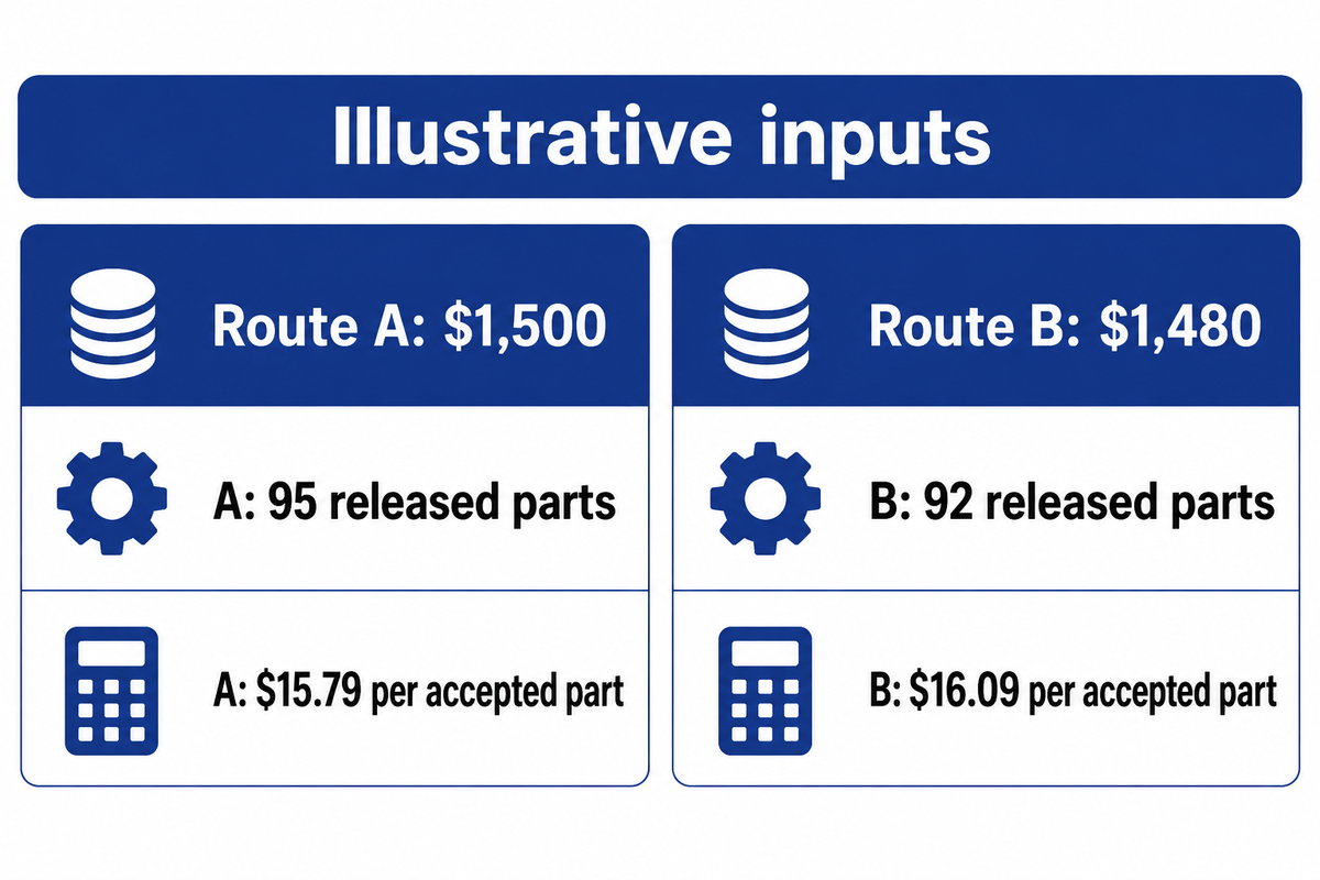
Compare automotive machining costs by dividing the batch cost by the released quantity. Include the costs for setup and fixtures, processing and inspection, and material without charging the same cost twice. CNC machining services and an in-house cell may be compared only after their scope, lot size and release criteria have been aligned.
The American Society for Quality cost-of-quality framework identifies prevention and appraisal activities as well as internal and external failures. Inspection uses up resources; scrap and rework affect cost of output. A lower machine hourly rate can therefore lose its advantage when the batch needs more setups or yields fewer released parts.
Good-Part Cost Bridge
The Good-Part Cost Bridge divides like for like batch costs by the quantity released under the same acceptance criteria.
| Same cost scope, USD | Route A | Route B |
|---|---|---|
| Programming, setup and fixture allocation | 300 | 600 |
| Material for 100 starts, after any credited recovery | 600 | 400 |
| Processing, including the specified finishing route | 450 | 300 |
| Inspection and release checks | 150 | 180 |
| Total batch cost | 1,500 | 1,480 |
| Parts started | 100 | 100 |
| Parts accepted and released | 95 | 92 |
| Cost per accepted part | 15.79 | 16.09 |
Route A costs $1,500 ÷ 95 = $15.79 per accepted part. Route B costs $1,480 ÷ 92 = $16.09 per accepted part. The route with the lower total batch spend is slightly dearer per released part. Both calculations use the same cost buckets and the same 100 starts. “Accepted” means released after the agreed dimensional and other required checks; pieces awaiting a decision are excluded.
Stock consumed by scrap is already accounted for in the batch’s material cost and therefore can’t be charged as scrap again. Rework labor that was not included belongs in processing before the division. Likewise, when an overall equipment effectiveness figure already includes its quality factor, applying the same quality loss again would understate output.
The production of automotive prototypes spreads setup across fewer parts, while repeated automotive production can spread it across a larger lot. A change in design can require a new program, fixture or blank tool before those savings are realized. Two advantages of CNC machining are program reuse and the ability to modify accessible contours, and their cost benefit hinges on batch calculation. The CNC machine acquisition cost guide addresses the equipment purchase; operating cost per released part needs the batch calculation as well.
At $15.79 per accepted part, Route A wins this worked example despite a batch total that’s $20 higher. Finance and production can replicate this calculation using their own accepted quantities and keep the cost scope the same. Adding a required finishing or transport charge to only one route changes that route’s total before division.
Automation: balance cutting, loading and gauging
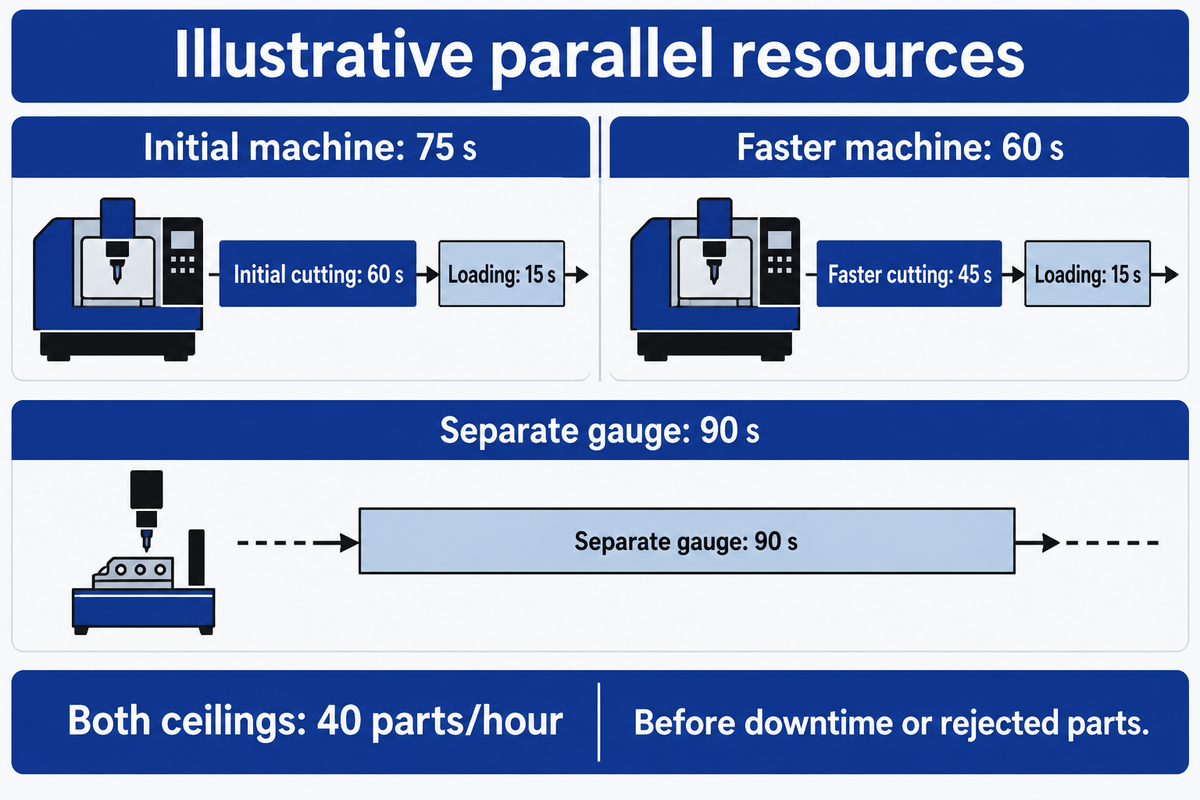
An automotive machining inspection bottleneck occurs when gauging limits output. Automate the limiting operation and measure which tasks can overlap. Loading, tool changes, inspection and corrective feedback can constrain a cell after cutting becomes faster. When planning CNC machines in automotive production, the product mix also changes the work at each station, so a single-part cutting demonstration doesn’t give complete capacity of the cell.
Mark Hall of Yamazaki Mazak, writing in The Engineer in June 2025, warns that bad use of automation can move a bottleneck. Integration of CNC equipment with robots needs suitable part presentation and fixtures. Plants that rely on CNC machining should include those interfaces as part of a capacity trial. Skilled CNC operators still handle prove-out, tool changes and abnormal conditions; unattended runtime needs those tasks planned into the system.
| Resource or activity | Initial example | After faster cutting | Constraint to measure |
|---|---|---|---|
| Cutting | 60 s/part | 45 s/part | Tool changes and in-cycle measurement are included in the measured cycle. |
| Loading at the machine | 15 s/part | 15 s/part | Serial with cutting in this example. |
| Machine occupied time | 75 s/part | 60 s/part | Cutting plus loading; do not count the two as parallel. |
| Separate gauge | 90 s/part | 90 s/part | One gauge, measuring every part while the next part is machined. |
| Ideal cell completion ceiling | 40 parts/hour | 40 parts/hour | The 90 s gauge remains the limiting resource. |
The example assumes independent machine and gauge resources. The example shows gauge-over-machining, where gauge resources overlap the next machining cycle. The ceiling is 3,600 seconds ÷ 90 seconds = 40 inspection completions per hour, before downtime or rejected parts. A decrease in cutting time from 60 seconds to 45 seconds leaves that ceiling unchanged. Without any overlap the initial 60 + 15 + 90 = 165 second cycle would allow a maximum of 21.8 completions per hour.
Feedback is another type of constraint. One example is a 2026 open-access study of automotive connecting-rod machining, which describes 100% automated tactile inspection followed by a manual adjustment of process parameters. Corrections take effect at least one or several workpieces later. Document the time from measurement to correction, and define how affected parts are held during that time. Also define the gauge cycle.
NIST’s 2018 multi-job production research analyzes throughput and bottlenecks as functions of product mix, with an automotive assembly application. For CNC machining in the automotive industry, repeat the exercise for the drawings of interest. Integrating CNC machining with one fast gauge is useful only if the fixtures and measurement program also handle the next part family.
A 90 s gauge limits the illustrated cell to 40 completions per hour, and its machine cycle time decreases from 75 s to 60 s. The buying decision then depends on inspection capacity, overlapping tasks or the agreed inspection plan. Faster machining delivers more completed parts after the limiting resource changes.
What to include in an equipment RFQ and acceptance trial
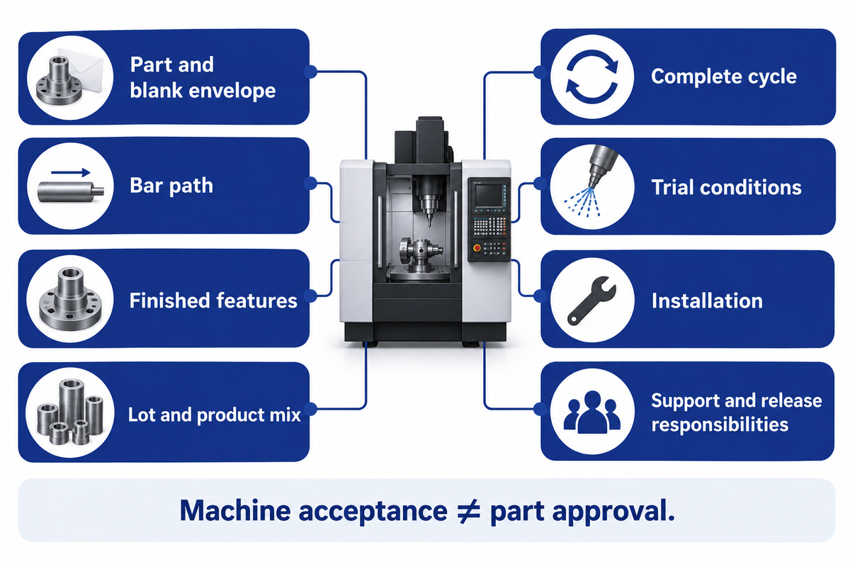
Automotive CNC machine manufacturers require drawings and blanks; the exact machine build; complete-cycle goals; and evidence for acceptance. Assign responsibility for fixtures, inspection and any part-performance qualification. Acceptance of the machine and the customer release of the automotive supplier address different deliverables, so provide each a named owner and agreed records.
AIAG’s APQP third-edition overview includes sourcing, change management, program metrics and risk assessment. Content of Control Plans is now part of a separate document. Automotive manufacturers and suppliers can now use plan and control requirements based on a customer-specific process and not turn a machine catalogue into a part approval package.
Equipment RFQ: define the measurements before requesting the trial.
| Parameter | Recommended range | Why it matters | How to verify |
|---|---|---|---|
| Part and blank envelope | Drawing sizes in mm; include minimum and maximum blanks | Stock and fixture sweep can exceed the finished shape. | Ask for a fixture/tool layout for the quoted build. |
| Bar path | Stock diameter in mm versus the smallest clear opening | A nominal spindle bore can hide a smaller drawtube. | Ask for the spindle, chuck and drawtube dimensions together. |
| Finished features | Drawing limits in mm and surface texture in µm | Size, form and surface texture need different checks. | Ask for the inspection plan and agreed decision rule. |
| Lot and product mix | Parts/lot and parts/shift for each drawing | Changeovers and different job times move the constraint. | Ask for a timed mixed-part trial and changeover record. |
| Complete cycle | Seconds/part through cutting, handling and inspection | A cutting-only quote can miss the slowest station. | Ask for timestamps and identify which tasks overlap. |
| Trial conditions | Agreed consecutive sample count and duration in minutes | A short machine study and long-run validation answer different questions. | Ask for raw sequence data, tool state and temperature history. |
| Installation | Supply voltage, kW demand and dimensions in mm | Utilities, floor loading and access affect readiness. | Ask for the exact build layout and site requirements. |
| Support and release responsibilities | Named owner, response time in hours and included services | Machine acceptance and customer part approval need clear owners. | Ask for the service scope, spares plan and acceptance records. |
ISO 22514-3:2020, confirmed current in 2026, describes short-term machine performance studies of consecutive parts under repeatability conditions. Its methods are unsuitable below 30 observations, and its public scope excludes expected tool-wear patterns and autocorrelation. Select a study method and duration relevant to the conditions of the trial; determine the measurement system to be used and the conformity rule with respect to the sequence data.
After an acceptable first-off, the trial should exercise the CNC machining used for the quoted capacity. Include the stated blank, the relevant tool state, loading and the checks needed after machining to ensure release criteria are applied. A smooth demonstration on one easy feature can conceal a second setup, a slow measurement or a support task that belongs in the production cycle. That full sequence is how CNC machining delivers a completed part to inspection.
Fewer than 30 observations fall outside the stated sample-size scope of ISO 22514-3:2020. The equipment trial still needs a method appropriate to its tool wear, data sequence and intended duration. Keeping the raw readings and conditions makes the machine result usable alongside the separate part-qualification and customer-release work.
Electric vehicles shift the mix of machined parts
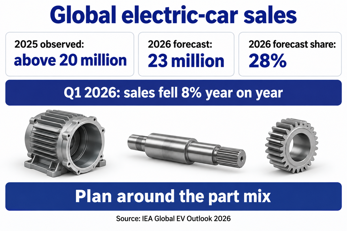
When considering the capacity of the machining center to produce electric vehicle (EV) components, it would be better to plan for the expected component mix and not add a general growth percentage to the capacity. Components of EVs, such as motor housings and reducer gears, may require different cutting and inspection tasks from components of an internal combustion engine. A plant that expects to run several different powertrains may need fixturing and changeovers to support the drawings it expects to run.
The International Energy Agency’s Global EV Outlook 2026 reports electric-car sales above 20 million in 2025, about one-quarter of new-car sales. Its 2026 forecast is 23 million and 28% of car sales. Those are global electric-car figures. The same report records an 8% year-on-year fall in global sales during the first quarter of 2026, alongside growth in several regions.
For machining in the automotive sector, the question is more about the product. An interview in the 2024 Modern Machine Shop discusses the ZF plant in Gray Court, and the co-existence of combustion, hybrid and electric drive systems. The interview touches on the balance of systems, gearing and drives; system assembly and cleanliness. It’s a great case study of balancing production to meet diverse customer demands.
For a plan involving equipment for 2026, group anticipated jobs by features turned, prismatic features, tooth processes and inspections. Based on the drawings, identify areas where fixture interfaces are allowed and group them, then find outliers that require a different class of machine or another setup. Across a changing part mix, CNC machining helps revise programs and accessible features; new material forms or inaccessible geometry can still require different equipment.
The adoption of CNC technology supports the automotive sector’s need to repeat defined cutting paths, but market totals cannot choose a spindle or fixture. In machining in automotive plants, CNC machining remains part of both established and emerging powertrain routes. During development, CNC machining supports prototype interfaces, before a dedicated high-volume blank route is ready. A buyer with combustion-engine orders and an uncertain electric-drive program should evaluate the capacity required for confirmed drawings, distinctly from the flexibility required for new work.
The IEA’s 28% figure is a forecast of the global share of car sales for 2026. Roughly translating this forecast into a shop floor plan would mean a part mix, not a proportional increase in spindle hours. A cell that switches between housings and shafts would mean that its loading and inspection constraints would need to be recalculated with that part mix.
Frequently asked questions
What is the best CNC machine for car parts?
A CNC lathe is the starting choice for rotational parts; a machining center is the starting choice for prismatic parts.
A shaft with concentric journals points toward turning, while a housing with pockets and angled holes points toward milling. A combined machine becomes useful when it removes costly transfers or setups for the actual drawing. Compare the complete cycle, fixture clearance and inspection route before selecting the extra axes. The finished part and intended lot determine the purchase.
What types of CNC machines are used in the automotive industry?
The main types include CNC lathes, milling centers, grinders and specialized gear equipment, with electrical discharge machines used for suitable conductive work.
Each class addresses different features. CNC milling machines cut faces, pockets and hole patterns; turning machines produce rotational surfaces. Finish machining is essential when a near-net blank leaves stock on those specified interfaces. Multi-axis machining extends tool access, while grinding and gear finishing address their respective drawing requirements. A 5-axis CNC machining center is therefore one option within a route, rather than a default machine for every car part or material.
What materials are used for automotive CNC machining?
Aluminum alloys, steels, cast iron and engineering plastics are used, with the grade, product form and heat treatment selected for the part.
The same broad material family can contain very different specifications. CNC machining can process a cast blank, a forging or wrought stock, but those routes give the part different starting conditions. Material selection must follow the drawing and its required performance qualification. Include certificates and any specified treatment in the procurement package, then match the tools and workholding to that material condition.
What is the difference between 3D printing and CNC machining for automotive parts?
CNC machining removes material; 3D printing builds a shape by adding material.
A combined route shows how CNC machining is employed after printing to finish accessible interfaces. Compare the final material condition, geometry and post-processing route.
Why is precision important in automotive manufacturing?
Precision matters because mating surfaces, clearances and geometric relationships affect how a part fits and functions.
The inspection plan must address the specified characteristic, including surface texture or position when required. Tighter size control alone can’t replace the other dimensional, material and component-performance checks. The advantages of automotive CNC machining follow from controlling those interfaces together.
Will CNC get replaced by AI?
AI can assist programming and monitoring; physical cutting, workholding and part release still require an engineered machining process.
The useful distinction is between software assistance and the operation it supports. A suggested toolpath still needs a suitable cutter, access to the feature and a fixture that holds the blank. CNC machining also includes proving that combination before production. Monitoring data can help identify a change without automatically proving that every finished part is acceptable. The 2026 connecting-rod study, for example, describes automated inspection with manual corrective feedback. Buyers can assess an AI-assisted feature by the task it performs, its inputs and the action it triggers. Include the response to a tool change, an abnormal measurement or a stopped cycle in the trial. Separate measured results from an expected improvement before allocating production capacity to the feature.
Specify the part route before the machine. A 66 mm spindle hole can still accompany a 50 mm bar limit, and faster cutting can leave a 90 s inspection constraint untouched.
Build the equipment brief around your drawings
Summarize the drawing, material condition, blank sizes and the accepted output. ANTISHICNC’s machine selection consultation can begin with lathes or machining centers that fit these requirements, followed by workholding, a trial run, and support for the proposed build.
Author: XCX. Updated October 2026. Machine examples use ANTISHICNC’s published technical proposals; production calculations state their example inputs. The references at the end identify the methods and studies used for the processes, quality and purchasing functions.
Related articles
- Understand the workpiece motion in CNC turning
- Build a CNC machine purchase budget
- Compare CNC lathe machine options
- Review the VMC650 machining-center platform
References & Sources
- Erie Institute of Technology: An Introduction to CNC Turning
- Reishauer application US20220291669A1: gear process monitoring, 2022
- Zoroufi and Fatemi: steering-knuckle fatigue comparison, SAE, 2004
- Open-die forging analytical cost model, 2020
- National Institute of Standards and Technology: Assessing Process Stability, section 3.4.5
- National Institute of Standards and Technology: Assessing Process Capability, section 3.4.6
- International Organization for Standardization: ISO 14253-1:2017 conformity decision rules
- American Society for Quality: Cost of Quality
- Mark Hall, The Engineer: automating CNC machining and bottlenecks, June 2025
- Automotive connecting-rod thermal measurement and process feedback study, 2026
- National Institute of Standards and Technology: Multi-Job Production Systems, 2018
- Automotive Industry Action Group: APQP third edition overview
- International Organization for Standardization: ISO 22514-3:2020 short-term machine studies
- International Energy Agency: Global EV Outlook 2026, Executive Summary
- Modern Machine Shop: ZF Gray Court and changing powertrain requirements, 2024