




What is CNC turning? CNC turning is a machining process that rotates a workpiece while a cutting tool, following a pre-determined path, produces a shape. An example is a shaft that has different diameters along its length, a groove, and a threaded end. A lathe can produce these features from the same centerline.
- Primary cutting motion: the workpiece rotates.
- Basic controlled axes: X across the diameter and Z along the spindle.
- Typical features: outside diameters, bores, faces, tapers, grooves and threads.
- Selection inputs: part drawing, stock dimensions, material, batch quantity and inspection requirements.
CNC turning is a subtractive machining process for producing rotational features with computer-controlled tool movement. A basic lathe uses the X and Z axes. Driven tools and additional axes extend the features a turning center can machine.
- A spindle opening can be larger than the installed bar passage; the smallest opening controls what passes through.
- Turning suits rotational features. Milling adds flats, pockets and other features outside that geometry.
- Cutting time covers the cut. Loading, tool changes, inspection and rejected parts affect production cost.
- Machine selection starts with the finished part and its workholding, then the installed equipment configuration.
CNC turning basics: process, lathe and turning center
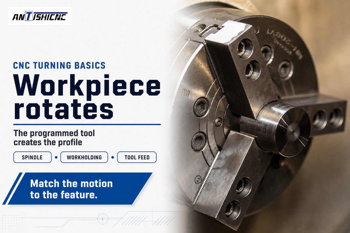
CNC turning shapes a rotating blank by controlling where a cutting edge contacts it. The spindle supplies rotation, while programmed axis movements determine diameter, length and profile. Because the cutting edge removes material as chips, the finished part is smaller than the starting stock wherever machining occurs.
A drill is a good comparison to a lathe. A hand drill’s tool spins into a stationary workpiece. In a conventional turning operation, it’s the workpiece that spins while the turning tool feeds along or across it. A tool that’s said to be stationary isn’t always motionless. It may move on slides but doesn’t provide the main rotation.
Purdue University’s lathe toolpath guide explains the rotating stock concept and distinguishes it from live tooling configurations. CNC stands for computer numerical control. The CNC control interprets a program and moves the axes, spindle, and other components supported by the machine tool.
Is CNC turning the same as a lathe?
No. CNC turning is the process, and a lathe is the machine that performs it. A manual lathe relies on the operator for a lot of tool movement, while a CNC lathe machine follows programmed movements. A turning center may also combine additional machining functions, but its name alone doesn’t specify its axes or tooling.
The base of the machine supports the assemblies that carry cutting loads. A headstock contains the spindle; a chuck or collet holds the stock; slides position the tools. A turret indexes between tool stations. Tailstocks, steady rests, driven tools and second spindles appear on some configurations, each serving a different purpose.
Example: A drawing requires a 25 mm shaft with a 20 mm bearing seat. Starting with larger round stock, an outside tool reduces the bearing seat to its size, leaving the shoulder intact. A groove tool then creates a relief next to the shoulder. Both features share the centerline of the spindle, making turning a natural process choice. A cross-hole through the shaft adds a different requirement: either a suitable driven tool or a different setup on a milling or drilling machine. The buyer may separate the basic rotational work from the other features before paying for additional capability. The smallest feature may not always determine the equipment required to perform the job.
For a shaft that steps from 25 mm to 20 mm, turning follows the change in radius while the blank rotates. Adding a cross-hole changes the required tool motion. These two features describe the basics of CNC turning better than equipment labeling: choose the cutting motions needed by the drawing.
CNC turning process: drawing to inspected part
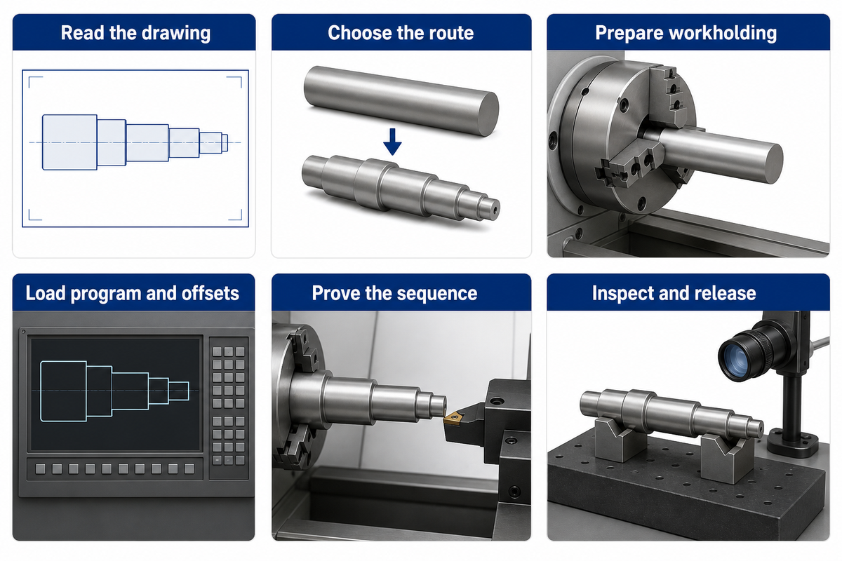
The CNC turning manufacturing process begins with a drawing and ends with an inspected part. Between the two, the shop chooses stock and tools, plans workholding, determines the best machining sequence, sets offsets, and proves the toolpath. Each step supplies information needed by the following step; control systems don’t replace the many steps needed to prepare the work.
- Read the drawing. Identify dimensions, datums, material, surface finish and any inspection requirements that affect function.
- Choose the route. Decide which features share a setup and which need the part reversed, transferred or machined elsewhere.
- Prepare workholding. Establish grip length, support, tool access and a protected path for any stock extending through the spindle.
- Load the program and offsets. Match the program revision, tool identities and work coordinate system to the setup.
- Prove the sequence. Follow the machine-specific simulation, dry-run and controlled first-piece procedures.
- Inspect and release. Measure the specified features, correct the process where needed and retain the setup record for the batch.
What Are the Basics of CNC Turning Programming and Software?
CNC programming defines machining commands and tool movements for a given control system and setup. Programs can be generated by hand, using conversational controls, or via computer-aided manufacturing. The University of Florida lathe training covers these program authoring methods. Toolpaths for features can be planned in a CAD/CAM system and appropriate machine instructions generated.
CAM software can create toolpaths, and, with the aid of a postprocessor, create CNC code. The postprocessor is configured for the CNC controller and machine. A CNC program also relies on tool and work offsets. Our CNC lathe programming guide covers tool and work offsets.
In a Practical Machinist discussion about repeat setups, contributor RJT suggests that program comments as well as photographs and setup sheets should be saved. A picture of jaw position may be all that’s needed to resolve an ambiguity that a tool number can’t. Document the actual layout, including tools that are removed to clear the subspindle. Not every repeat job can use the previous turret layout unchanged.
A repeat order for the same 25 mm shaft can reuse a proven program, but the setup details such as stock projection, jaws and tool offsets still need to be saved. Those details assist in reproducing the setup. The purchase of new software won’t help eliminate the work of holding and measuring the first part and proving it safely.
Types of CNC turning operations and their features
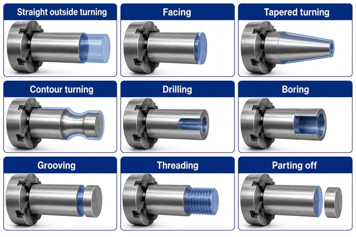
Different turning operations produce features on or around the axis of a workpiece. Outside turning changes an external shape; a facing cut creates an end; and a boring tool increases the size of a hole. Grooving, threading and parting require separate cutting and tooling. It’s better to identify a feature on a drawing and name the operation rather than trying to figure out which tool station is available to perform that operation.
| Operation | Feature produced | Planning detail |
|---|---|---|
| Straight outside turning | Cylindrical outside diameter | Allow material for roughing and finishing. |
| Facing | Flat end face | Establish face position and tool clearance. |
| Tapered turning | Diameter changing along length | Coordinate X and Z movement to the specified profile. |
| Contour turning | Curved or stepped profile | Check insert shape and access around shoulders. |
| Drilling | Initial axial hole | Provide drill reach, chip removal and coolant access. |
| Boring | Enlarged or profiled existing hole | Match bar diameter, overhang and starting-hole clearance. |
| Grooving | Recess for a seal, ring or relief | Specify width, depth, corner form and access. |
| Threading | Internal or external helical thread | Specify thread form, pitch, class and inspection method. |
| Parting off | Separated component | Plan tool clearance and controlled part collection. |
Purdue University’s operation guides show both outside and inside toolpaths. Turning and boring use related motions on opposite sides of the material. Outside tools approach an exposed surface. Boring bars first have to enter a hole large enough for the bar and insert, and their unsupported length affects tool stiffness. A small hole with a deep internal shoulder may control tool selection even when the external shape seems simple.
Threading in CNC turning states another constraint: tool travel and spindle rotation have to be synchronized to achieve the desired pitch of a thread. Just because a tool can access the same location as a thread insert doesn’t mean a generic grooving tool can take the place of a thread insert. Tool and cutting needs are determined by the geometry and finish of a feature.
Hard turning refers to cutting hardened workpieces with the proper tooling and adequate rigidity in the machine setup. This doesn’t provide a separate guarantee of accuracy. CNC turning materials can include various types of steels, stainless steels, aluminum alloys, and machinable plastics, to name a few. These materials, however, don’t all cut the same way. The condition and grade of the material need to be on the drawing prior to choosing the tooling, speed or feed.
Consider turning and drilling followed by boring to prepare a part with a 20 mm outside seat and 10 mm bore. This operations sequence can prepare different surfaces on the part and the bore depth with tool clearance can set a practical limit. More turret positions help only when the tools for the other surfaces can reach them without interfering with each other.
CNC turning vs milling: choose by finished geometry
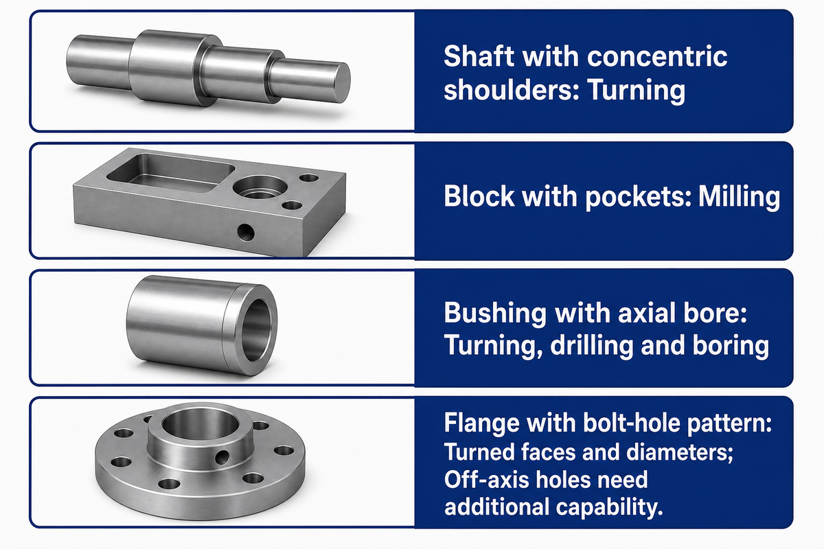
When comparing CNC milling and CNC turning, a design with features aligned with a common axis like a central bore and shaft diameters suits turning for those features; other geometry may require milling. For features like pockets and flat faces best prepared by a rotating cutter, milling is favored. In cases where both processes are required, the choice is how to split the work and control transfers.
A good comparison to show the relative difference in each process, CNC turning vs CNC milling, is to identify which component (if any) rotates. In a CNC mill, the workpiece and tool are positioned relative to each other and the cutter is allowed to rotate. In a CNC turning machine, the workpiece is allowed to rotate for the main cutting actions. CNC turning and CNC milling have different strengths; neither process is universally faster when the drawing, setup and inspection scope differ.
| Finished geometry | Starting route | Reason to add another operation |
|---|---|---|
| Shaft with concentric shoulders | Turning | Cross-holes, flats or keyways |
| Block with pockets | Milling | Rotational features requiring another holding strategy |
| Bushing with axial bore | Turning, drilling and boring | Off-axis mounting features |
| Flange with bolt-hole pattern | Turned faces and diameters | Driven tooling or a separate drilling/milling setup |
Example: A 40 mm flange requires a 20 mm hub and four off-axis mounting holes. A two-axis lathe can face the part and turn its hub, but the four holes still require positioning and drilling capability. A live-tool turning center may finish the part in fewer transfers; using a mill may make sense if the other machine is already set up and the batch is small. The comparison should include the cutting time for each spindle as well as the time spent relocating the part and inspecting the relationship between features. Controlled spindle positioning, or a C-axis, locates features around a part, and a Y-axis adds transverse travel. The driven toolholder and control need to support the required operation.
Manual equipment also has a place. In its 2025 Aerotech report, Modern Machine Shop describes infrequent large-shaft work for which the shop used a newly purchased manual lathe. That’s a concrete example of matching investment to the work mix rather than buying CNC technology for every operation.
The advantages of CNC turning include repeating programmed paths and efficient sequences for rotational work. The disadvantages of CNC turning include setup effort and restraints on tool access and geometry. To view our in depth comparison, see our guide on milling and turning.
Types of CNC turning machines and applications
Different types of CNC turning machines vary in the orientation of the spindle, type of work support and combination of operations. A horizontal turning center adapts to various layouts of shafts and bar work; vertical turning centers support work on a horizontal table or chuck. Depending on the tools and additional drives, a difference in the number of possible work sequences can be achieved.
Horizontal CNC lathes place the spindle axis horizontally. A tailstock or steady rest can be used to support longer work, and a bar feeder can be used to load work via the spindle for continuous cutting. A vertical spindle in other models, known as vertical CNC lathes, changes how larger and heavier workpieces are loaded and supported.
A basic CNC turning lathe is usually focused on rotational cuts. A CNC turning center with driven tools can perform selected drilling and milling operations. Multi-axis turning equipment can provide a Y axis, position and coordinate spindles. Each of the added axes brings added complexity for programming and maintenance.
Examples of cylindrical parts in CNC turning applications include shafts, bushings, threaded fittings, rollers and flanges. Length and support are important with shafts, while wall thickness and bore access are important with bushings. Gripping and face diameter are important with flanges. For flanges, other factors may include offset holes, keyways and cutouts. Those applications of CNC turning may share the same basic process while requiring different machine arrangements.
ANTISHICNC supplies CNC lathe configurations with different working envelopes. As an example, the CK6130 quotation limited the maximum turning length to 230 mm, and the 235 LANCEN quotation increased it to 550 mm. These distinctions are necessary before assessing control options and/or turret features. An available 550 mm envelope may suit a length requirement greater than 230 mm, but tooling and workholding still consume space.
A 300 mm-long part already exceeds the CK6130’s listed 230 mm turning length. The 235 LANCEN’s listed 550 mm length gives a larger starting envelope. Comparing those dimensions first helps keep different types of CNC equipment tied to the job, instead of viewing every lathe machine as being equal.
CNC lathe capacity: four checks before selecting a machine
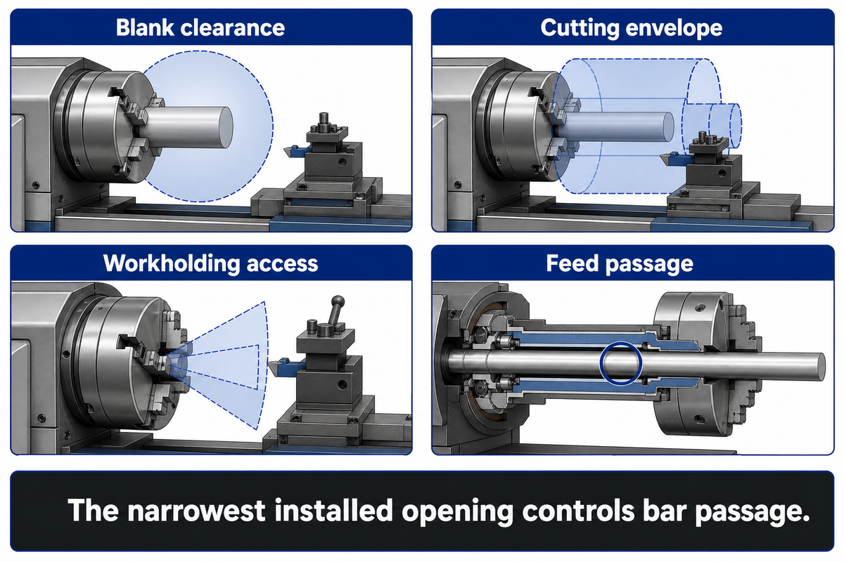
The capacity of a CNC lathe combines space for the workpiece, the cutting envelope, workholding and the feed passage. Different limits are described by swing over the bed, the maximum turning diameter and spindle bore. A part must fit the complete, entirely coupled setup, before assessing the machining route as being feasible.
4-Envelope Fit Check
The 4-Envelope Fit Check compares blank clearance, cutting travel, workholding access and the installed feed passage against one part drawing.
- Blank clearance: the uncut stock and its fixtures must clear the bed and surrounding structure during rotation.
- Cutting envelope: the tools need sufficient diameter and length travel to reach the finished features.
- Workholding access: jaws, holders, tailstock and turret must grip and support the work without blocking the required movements.
- Feed passage: bar stock must pass the narrowest installed opening, including the drawtube where fitted, chuck or collet, and feeder interfaces.
ANTISHICNC’s published quotations demonstrate how these checks remain distinct. The values listed below are examples of supplier-listed configurations, in which paired options are kept together.
| Model | Turning length | Spindle opening | Listed bar diameter | Drawtube / tie-rod opening |
|---|---|---|---|---|
| CK6130 | 230 mm | 48 mm | 45 mm | 40 mm, optional hollow-chuck arrangement |
| 235 LANCEN | 550 mm | 66 mm | 50 mm | 50 mm |
| CK6140/550 | 420 / 300 mm, 6 / 8 stations | 48 / 82 mm alternatives | 40 / 65 mm, paired alternatives | Specify selected chuck arrangement |
| CK6150/1000 | 850 / 730 mm, 6 / 8 stations | 82 / 130 mm alternatives | 80 / 128 mm, paired alternatives | 65 / 118 mm optional alternatives |
| CK6160/1500 | 1,350 mm | 130 mm | 128 mm | 118 mm, optional hollow-chuck arrangement |
Example: a buyer plans to feed 42 mm round bar through a CK6130. The 48 mm spindle opening initially looks large enough. However, the quoted optional hollow-chuck arrangement has a 40 mm tie-rod opening. The 42 mm bar can’t pass that opening, even though it’s smaller than the spindle bore and the separately listed 45 mm bar diameter. The purchasing decision must therefore specify a compatible installed passage or use a different production route. Cutting the bar into blanks for chucking changes loading and handling, so that alternative also changes the cycle estimate. Selecting the largest number from each catalogue row would conceal the constraint instead of solving it.
On Practical Machinist, there are numerous posts which detail the same types of limitations with draw tubes, chucks and retaining hardware. There’s also the issue of the stock’s straightness: material that’s near the nominal bore size can bind, even if it appears to fit. There are multiple choices for workholding, which alters the access and the grip. Our collet type guide covers this aspect of setup.
Satisfactory support and guarding must be provided, in addition to the static fit checks, for rotating stock. A Washington FACE investigation describes a fatal accident involving approximately 3 ft of unsupported bar projecting beyond a lathe spindle. There’s no safe projection or speed that can be generalized and inferred from the bore diameter.
The CK6130’s optional 40 mm passage excludes 42 mm through-fed bar despite its 48 mm spindle opening. A suitable bar path must also be supported and guarded for rotation. Match the complete installed passage and support system to the stock.
CNC turning speed, feed and cutting time
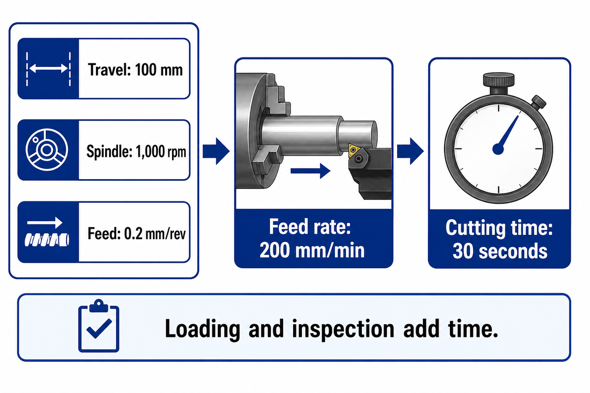
Different quantities are represented by different terms. Spindle speed measures the speed of revolution. Cutting speed measures surface travel per minute, while feed measures tool advance per revolution. For a constant-speed straight cut, time required to do the cutting is equal to tool travel divided by the feed rate. Time is also consumed for loading and other non-cutting operations.
In metric units, cutting speed is vc = π × D × n ÷ 1,000, where D is workpiece diameter in mm and n is spindle speed in rpm. Linear feed rate is Vf = f × n, where f is feed in mm/rev. Cutting time in minutes is Tc = L ÷ (f × n) where L is tool travel in mm.
Mitsubishi Materials’ metric turning formulas include a 50 mm diameter at 700 rpm, which gives approximately 110 m/min cutting speed. Its cutting-time example uses a 100 mm cut, 1,000 rpm and 0.2 mm/rev. The feed rate is 0.2 × 1,000 = 200 mm/min; 100 ÷ 200 = 0.5 min, or 30 seconds.
That 30-second result captures the specified cutting segment. A shop scheduling the job must consider approach and retract movements, tool changes, clamping, loading and inspection as applicable. Several cuts may be needed to achieve the final diameter. Converting 30 seconds straight into 120 accepted parts per hour would be giving no credit for the above-mentioned activities and interruptions. The formula is still useful as it helps to focus on one element of the cycle, i.e. a changed feed or travel length, and evaluate the effect of that change. The rest of the production system cannot be ignored.
A low turning speed or high turning speed is only meaningful when data for the material and the cutting tool is provided. With constant rpm, larger diameter implies higher surface speed. Constant surface speed control alters rpm with respect to changes in diameter. The program still needs appropriate speed limits for work holding and the workpiece. Facing toward the center is different from making a constant diameter longitudinal cut.
Feeds and depths of cut should be taken from the selected tool’s guidance and the condition of the workpiece, and checked during the setup. Doubling feed changes cutting load and finish requirements as well as time. For imperial surface-speed calculations and unit handling, use our surface-speed calculation guide.
A 100 mm cutting path at 1,000 rpm and 0.2 mm/rev takes 30 seconds at constant feed. The same calculation doesn’t include loading or measurement. Separating cutting time from the remaining cycle lets a production planner identify whether tooling changes or handling improvements address the larger delay.
CNC turning cost and machine quotation requirements
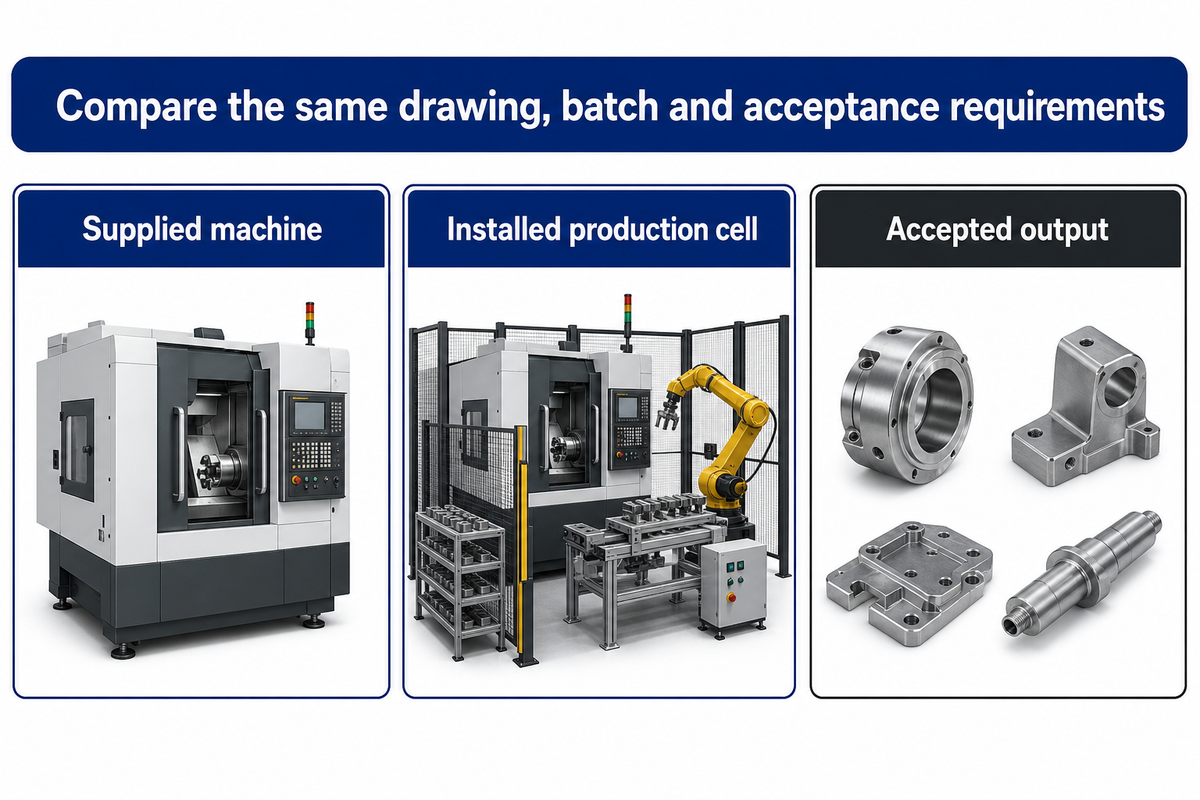
The cost of CNC turning depends on the entire production process, including the cost of the stock, the setup, machining and turning time, tool and quality losses, and the cost of handling. A quote for a finished part covers a different scope from a quotation for the machine. For comparable quotes, the same drawing and specifications are required, as are the batch size and acceptance requirements.
3-Scope Quote Check
The 3 Scope Quote Check separates the cost of the supplied machine, the cost of the installed production cell, and the cost of the accepted output.
In the scope of the supplied machine, equipment and options are identified. In the scope of the installed production cell, tools, workholding, equipment for loading and utilities, commissioning and training are quoted. The scope of accepted output includes the time and consumables needed to produce conforming parts. A lower price for a supplied machine can result in a higher installed cost, if essential items aren’t included in the offer.
| Decision field | Information to send or request | Cost or capacity decision |
|---|---|---|
| Part and stock | Drawing revision, material condition, stock dimensions | Defines removal volume and starting envelope. |
| Volume and mix | Batch size, repeat frequency, part families | Allocates setup and changeover effort. |
| Installed configuration | Spindle, turret, axes, controller and selected options | Prevents comparison of different capabilities. |
| Workholding and support | Jaws or collets, drawtube where fitted, tailstock or rest | Reveals passage and tool-access bottlenecks. |
| Tooling and consumables | Holders, inserts, drills, coolant provisions | Separates supplied equipment from recurring expense. |
| Loading and collection | Bar feeder, manual loading, robot or part catcher | Sets handling time and unattended boundaries. |
| Site and commissioning | Power, air, floor space, delivery, installation and training scope | Builds the installed-cell cost. |
| Trial and inspection | Representative drawing, measurement method, agreed sample sequence | Connects acceptance to the intended work. |
| Output-cost assumptions | Complete cycle, staffing, tool life, scrap and rework assumptions | Allows a consistent accepted-part comparison. |
For an illustrative $200 setup, allocation is $200 divided by batch quantity: at 10 pieces, setup contributes $20 per piece; at 100 pieces, it contributes $2 per piece. (The arithmetic is the same as the University of Texas batch-processing model.) The costs of the materials, cutting, inspection, and losses must then be added. Producing a batch of 100 pieces to reduce the cost allocation to setup may result in more inventory than is actually needed. A better improvement may be a shorter setup time. Thus, the total cost should be compared to the expected orders to determine the optimal batch size, instead of reducing one of the costs and ignoring the others.
The American Society for Quality’s cost framework puts inspection as part of appraisal and scrap and rework as part of internal failures. Those categorizations explain why the cost per accepted part can increase while nominal machining time stays the same.
Equipment buyers purchase production capacity, and part buyers using high-precision CNC turning services purchase components. The same drawing can support both requests. Use the nine fields to request a like-for-like offer, including the acceptance method and who supplies each item.
With a $200 setup, spreading the work across 100 pieces instead of 10 reduces the setup allocation from $20 to $2 per piece. Total cost can still increase through excess inventory, inspection or rework. The 3-Scope Quote Check keeps that arithmetic connected to the machine, cell and accepted output.
CNC turning quality: prove the part, not a generic tolerance
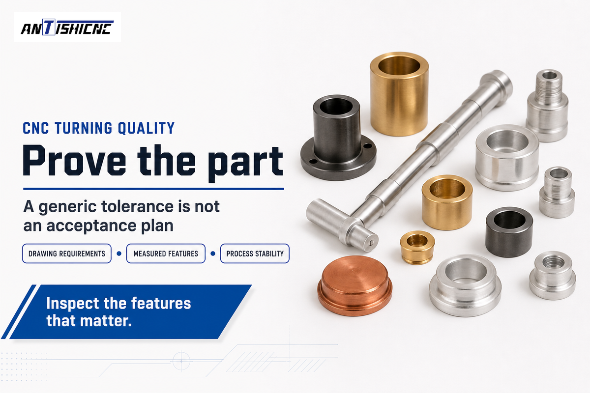
Precision CNC turning starts with the ability to understand and interpret requirements. It then proceeds to demonstrate a process that’s capable of repeatedly producing to those requirements. Many factors influence the final outcome including workholding, tooling, materials, fixture, thermal conditions and measurements. First piece inspection checks the initial setup. Time ordered measurements help determine how the process behaves and tools wear as the batch continues.
A good acceptance record helps to document the revision of the drawing that establishes the requirement. It should include the material, installed configuration of the tools, measuring instruments, and measurement method. Record dimensions with units and distinguish surface finish requirements from size requirements. CNC turned parts might meet a diameter requirement, but have an unacceptable finish, taper or relationship between features. A general machine-accuracy figure can’t take the place of these individual requirements.
NIST’s process-stability guidance places stability of the process before determination of its capability. The stability of a process relates to the distribution, mean and variance over time. One acceptable first piece answers a different question than a subsequent sequence measured during tool wear.
NIST’s 2026 research on thermal deformation identifies heat from motors and processing, together with ambient changes, as influences on machine geometry and part quality. A sample process sheet, retaining time and thermal conditions, coupled with measured diameters, would help determine if a gradual drift of the process was happening or if a one time measurement error occurred.
Tool reach also matters. Long boring bar overhang and unstable clamping are listed by Sandvik as causes of vibration. A deep bore may require different holder and bar arrangements before changing cutting parameters. A potential buyer of advanced turning equipment wouldn’t benefit from the increased axis travel if the boring tool still lacks stiffness at the required reach.
“The point of operation of machines whose operation exposes an employee to injury, shall be guarded.”
The applicable guarding and training arrangements, along with dimensional acceptance, are needed for installation and operation. ISO 23125:2015 addresses turning-machine safety and remained the published edition confirmed in 2026. In the context of production and purchase planning, it needs to be ensured that neither equipment protection nor part quality is eliminated from production because the other was ensured.
CNC turning outlook: automation still needs a stable process
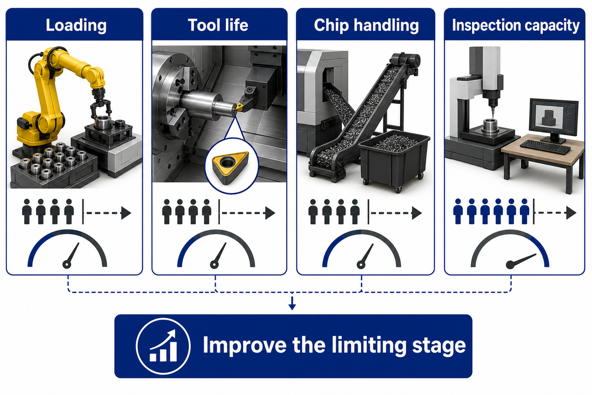
Investment in automation should address the constraint that limits accepted output, be it loading, tool life, chip handling, or inspection. A feeder may extend the supply of material while some other part of the process demands attention. Modern CNC equipment is most helpful when additional functions are added to address specific production constraints.
A case at Custom Tool illustrated by Modern Machine Shop concerned a threading tool that required attention. A threading tool needed attention after roughly 4 hours; redundant tooling helped extend the operating window. This shop also addressed chip handling and part collection, and ultimately, inspection capacity became a bottleneck. The lesson from this shop is to evaluate the entire route before extending a shift.
Advanced CNC functions can be useful for monitoring and coordination. However, a sensor or robot can’t discern which elements are critical to the customer. For acceptance, the plan must show how alarms and tool changes are related to the measured features that are critical to the customer. When a tool reaches its agreed life or a measured feature drifts, the production process needs a defined response rather than continued loading.
There are also signs in the market to invest in automation and equipment. AMT’s June 8, 2026 release reported $593.6 million in April US metalworking machinery orders, up 33.2% from April 2025 and down 12.5% from March. These figures represent a dated series on US machinery orders, not the global CNC turning market. They provide context for investment activity, not a payback forecast for an individual lathe.
Most important for a new cell is a matched loading, tooling, collecting and inspection plan for the part family chosen. Adding a second spindle may eliminate a handling step; however, better inspection capacity may be more valuable if parts accumulate after they’re machined. The judgement of the capabilities of CNC lathes or turning centers should be made with this constraint in mind.
A tool that needs attention after 4 hours may limit an unattended interval, even if the bar feeder has enough stock for a longer time. The Custom Tool case illustrates the need to integrate material capacity with tool life and inspection. The more useful approach is to extend the shortest operating window, rather than increase capacity for an unconstrained step.
CNC turning FAQs
What are the downsides of CNC turning?
CNC turning adds setup effort, produces chips and requires extra operations for some off-axis features.
What Are The Machine Axes In A CNC Turning Center?
A basic CNC turning center uses X and Z axes; other installed axes extend its movements.
What are the Key Design Considerations for CNC Turning?
CNC turning design starts with rotational geometry, stock, workholding and functional tolerances.
What is CNC in simple terms?
CNC is the abbreviation for computer numerical control.
Can you give me an example of a CNC machine?
CNC lathes and CNC milling machines are two examples of computer-controlled machine tools.
What is a CNC turning operator?
A CNC turning operator prepares or runs the equipment within their training and assigned role.
When should a buyer outsource CNC turning instead of buying a lathe?
Outsourcing suits occasional or uncertain work; equipment ownership deserves evaluation for recurring demand.
Match the lathe to the part
Use the 4-Envelope Fit Check to narrow the machine configuration, then the 3-Scope Quote Check to compare offers. Explore ANTISHICNC’s lathe range or discuss your part drawings with the team, including stock dimensions, batch quantities and the features that need inspection.
The model values cited above are from the published technical quotes for ANTISHICNC reviewed in October 2026. Calculations use the provided values, and outside shop examples are given by their authors. Use the part acceptance requirement to select the options in the final quote.
References & Sources
- Lathe Toolpath Guide Purdue University.
- CNC Lathe Resources University of Florida.
- “Washington FACE Report 10WA001” (2012), Washington State Department of Labor and Industries, archived by CDC.
- “Work in Process Models” University of Texas.
- “Cost of Quality” American Society for Quality.
- “Assessing Process Stability” NIST Engineering Statistics Handbook.
- In-process Optical Measurement and Compensation of Machine Tool Thermal Deformations, NIST, 2026.
- General Requirements for All Machines, 29 CFR 1910.212 OSHA.
- ISO 23125:2015, Machine Tools, Safety, Turning Machines ISO catalogue, confirmed 2026.
- The Unattended Effects of CNC Machine Shop Automation, Derek Korn, Modern Machine Shop, 2018.
- “Where Manual Turning Is as Valuable as CNC” Evan Doran, Modern Machine Shop, 2025.
- “Automation Fuels Strong Start to 2026 Manufacturing Technology Orders” AMT, June 8, 2026.