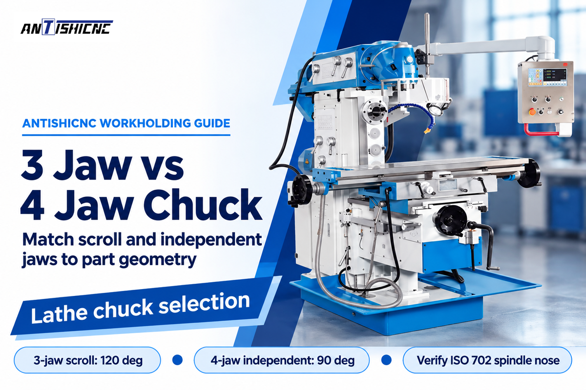






Choosing between a 3 jaw vs 4 jaw chuck comes down to workpiece geometry, datum runout tolerance, and batch setup time. A three-jaw chuck can clamp round or hexagonal stock within seconds using its self-centering mechanism. A 4-jaw independent chuck uses four separate leadscrews to center the workpiece on the spindle axis. Machinists use it to dial in square, rectangular, irregular, or eccentric stock to tight concentricity. Its independent jaw adjustment provides exceptional versatility across one-off repair and toolroom jobs. This guide compares scroll and independent kinematics, ISO 3089 and ISO 702 standards, thin-wall deformation, soft-jaw boring math, and spindle pairing.
Quick Engineering Summary: 3-Jaw Scroll vs 4-Jaw Independent Chucks
- Standard 3-jaw scroll chucks space three jaws at 120 degrees and move them together via a bevel pinion and scroll plate. The field radial runout is generally 0.002 to 0.004 in. (0.05 to 0.10 mm) TIR on a ground test bar in a standard plain-back chuck. They fit fast bar loading on round and regular hexagonal stock.
- Micro-adjustable 3-jaw scroll chucks (for example, Pratt Burnerd Griptru) add radial fine-adjustment screws over an adapter boss. Pratt Burnerd reports 0.005 mm TIR repeatability on duplicated round parts for its Griptru chucks after specified mounting and centering adjustments. Always tighten the chuck through the single marked pinion socket.
- 3-Jaw Chuck with Bored Two-Piece Soft Jaws: Replaceable serrated or tongue-and-groove top jaws are machined in place under preload matching the intended gripping direction, clamping force, and axial contact position. They hold 0.0005 to 0.0015 in. (0.013 to 0.038 mm) TIR for repeat second-operation batches.
- Four reversible jaws on independent chucks space 90 degrees to each other on separate perimeter lead screws. They center square, rectangular, casting, and off-center work within dial indicator resolution, subject to spindle radial motion and form error of the workpiece.
- Spindle nose interfaces follow ISO 702-1:2009 (Type A1 and A2 short taper), ISO 702-2:2007 (Camlock D1), and ISO 702-3 (bayonet mount). Static scroll geometry follows ISO 3089:2005, while chuck design safety work continues under ISO/WD 16156.
Direct Selection Rule. Pick a 3-jaw self-centering scroll chuck when turning round or hexagonal bar in a single clamping. For repeat second-operation batches, pair a 3-jaw chuck with preloaded bored soft jaws tightened at the single marked master pinion socket. Pick a 4-jaw independent chuck for square or irregular castings and deliberate crankshaft offsets. It also does re-chucking pre-machined datums below 0.001 in. (0.025 mm) TIR, without soft-jaw tooling.
This guide covers industrial metalworking manual and computer numerical control (CNC) lathe chucks. The ANTISHICNC machine specifications cited below are drawn from model-specific technical quotations and product documentation. International standards, OEM chuck manuals, and patent documents are owned by the respective authorities.
3-jaw vs 4-jaw chuck selection for round and square workpieces
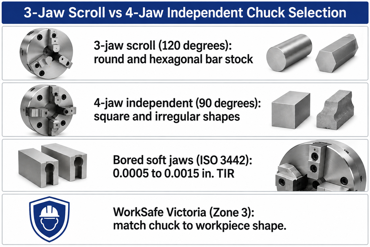
Pick a 3-jaw scroll chuck for cylindrical or hexagonal bar stock that needs sub-minute loading. Pick a 4-jaw independent chuck for square, asymmetric, or ultra-concentric second-operation parts. Three jaws spaced at 120 degrees self-center round stock automatically. By contrast, four independently adjustable jaws spaced at 90 degrees grip the flats of square stock and allow indicator-guided centering.
Official workplace safety guidance from WorkSafe Victoria (Zone 3) states this primary shop rule directly. Operators should use a 4-jaw chuck for irregular shapes and a 3-jaw chuck for round workpieces. Some turning jobs require other specialized workholding, such as 6-jaw compensating chucks, dead-length collet chucks, or radial-pole electro-permanent magnetic chucks, which are setups where our engineering guide to lathe chuck types should be consulted.
The Scroll-vs-Independent Concentricity Matrix below catalogues the key attributes of the four jaw setups used in toolroom engine lathes and in production turning centers. Each row presents mechanical drive kinematics, likely radial runout, and clamping geometry. You can match the chuck to your part drawing before starting setup.
| Engineering Parameter | Standard 3-Jaw Scroll Chuck (Hard Jaws) | Micro-Adjust 3-Jaw Scroll (Pratt Burnerd Griptru) | 3-Jaw Chuck with Bored Soft Jaws (ISO 3442) | 4-Jaw Independent Chuck (Hard Jaws) |
|---|---|---|---|---|
| Jaw Spacing & Drive Mechanism | 3 jaws at 120 deg; planar spiral scroll plate + 3 bevel pinions | 3 jaws at 120 deg; scroll plate + 3 fine-pitch radial micro-adjustment screws | 3 jaws at 120 deg; two-piece serrated or tongue-and-groove top jaws | 4 jaws at 90 deg; 4 independent perimeter leadscrews |
| Typical Field Radial Runout (TIR) | 0.002 to 0.004 in. (0.05 to 0.10 mm) new plain-back benchmark (0.002 to 0.005 in. out of box) | 0.005 mm (0.0002 in.) TIR repeatability on duplicate round parts per Pratt Burnerd manual | 0.0005 to 0.0015 in. (0.013 to 0.038 mm) when bored under matching preload | Dialed to indicator resolution (0.0002 to 0.001 in., bound by spindle motion and part form) |
| Governing ISO Standard Scope | ISO 3089:2005 (static geometrical tests for manual one-piece hard jaws) | OEM micro-adjust test bar spec + ISO 3089 static geometry | ISO 3442-1/2/3 (two-piece jaw interface dimensions and static interchangeability) | ISO 19719 vocabulary + ISO 702 spindle mounting registers |
| Primary Workpiece Shapes | Symmetrical round bar, regular hexagonal stock | Precision ground round blanks, bearing shafts, gauge pins | Second-op turned blanks, stepped shafts, thin-wall sleeves (pie jaws) | Square stock, rectangular blocks, valve castings, off-center crankshafts |
| Initial Setup & Per-Part Loading | Zero dial-in; 10 to 30 sec per part with a single chuck key | 3 to 5 min initial boss truing; 15 to 30 sec repeat loading on marked “0” pinion | 15 to 20 min jaw boring setup; 10 to 20 sec per part in production | Dial-indicator truing and clamping require 1 to 6 minutes per workpiece |
| Jaw Reversibility (OD vs ID Grip) | Numbered one-piece scroll jaws can grip small outside diameters or expand into bores using their stepped faces; a matched reverse-stepped jaw set extends the external gripping range | Two-piece reversible top jaws or separate numbered solid jaw sets | Machinable aluminum or 1018 steel top jaws bolted to master jaws | Each stepped hard jaw unthreads and reverses 180 deg independently |
| Thin-Wall Ring Distortion Risk | High 3-point concentrated load causes triangular (three-lobed) springback | High with narrow hard jaws; bored soft jaws with broader contact can reduce distortion. A six-jaw chuck is a separate workholding option | Low when machined as full-wrap 6061-T6 or 1018 pie jaws | Moderate; 4 narrow jaws shift deformation to four-lobed square springback |
| Crash & Interrupted-Cut Durability | Moderate; heavy parting crashes can crack spiral scroll teeth | Sensitive; heavy interrupted cuts can shift micro-adjust boss alignment | High on serrated power chucks; top jaws absorb minor tool contact | Heavy independent leadscrews and solid body tolerate interrupted cuts when securely clamped |
| Maximum Operating Speed | Chuck and jaw ratings, remaining gripping force, and workpiece balance limit operating speed | Pratt Burnerd Griptru: listed ratings of 2,300 to 4,900 rpm for 160 to 315 mm bodies, depending on size and grade | Top-jaw mass and extension increase centrifugal loading and reduce available external gripping force | Eccentric workpieces and asymmetric jaw extension can require reduced speed |
How scroll plates and independent jaw screws machine each shape
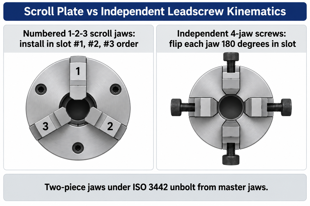
A 3-jaw scroll chuck drives all three jaws simultaneously through a bevel pinion and a flat spiral scroll plate. By contrast, a 4-jaw independent chuck drives each jaw through its own radial leadscrew. This internal mechanical difference dictates how you load parts, sequence jaws, and position the workpiece centerline.
What Are the Core Mechanical Differences Between a 3-Jaw and a 4-Jaw Chuck?
A 3-jaw scroll chuck moves all three jaws together through a hardened scroll plate with a continuous spiral tooth. A 4-jaw independent chuck moves each jaw separately, through its own Acme or square thread screw. In a scroll chuck, turning the chuck key in any pinion socket rotates a bevel gear which drives the scroll plate. All the three scroll jaws mesh with that spiral tooth and move inward or outward at the same radial rate. A 4-jaw independent chuck has no internal scroll plate. Turning one perimeter screw moves only that single jaw while the other three jaws stay stationary.
This kinematic split enforces strict rules for jaw installation and reversal in the shop.
- Numbered 1-2-3 scroll jaws require strict slot sequencing. The planar spiral scroll advances by one full pitch per revolution. Teeth on one-piece 3-jaw chuck jaws are offset by one-third of a pitch between jaws #1, #2, and #3. You must engage jaw #1 into slot #1 first as the scroll lead passes, followed by #2 and #3 in order. Installing a jaw out of sequence throws the three jaws off center and can jam or fracture the scroll tooth.
- Independent 4-jaw screws allow individual jaw reversal. On a 4-jaw independent chuck, every lead screw is mechanically isolated. One simply backs each screw out, flips the stepped jaw 180 degrees end-for-end, and threads it back into the same slot. Numbered one-piece scroll jaws can grip small outside diameters or expand into bores using their stepped faces. A matched reverse-stepped jaw set extends the external gripping range. Chucks with two-piece jaws under ISO 3442 unbolt or reverse the top jaws independently of the master jaws.
Radial runout and concentricity limits: ISO 3089 vs dialed 4-jaw
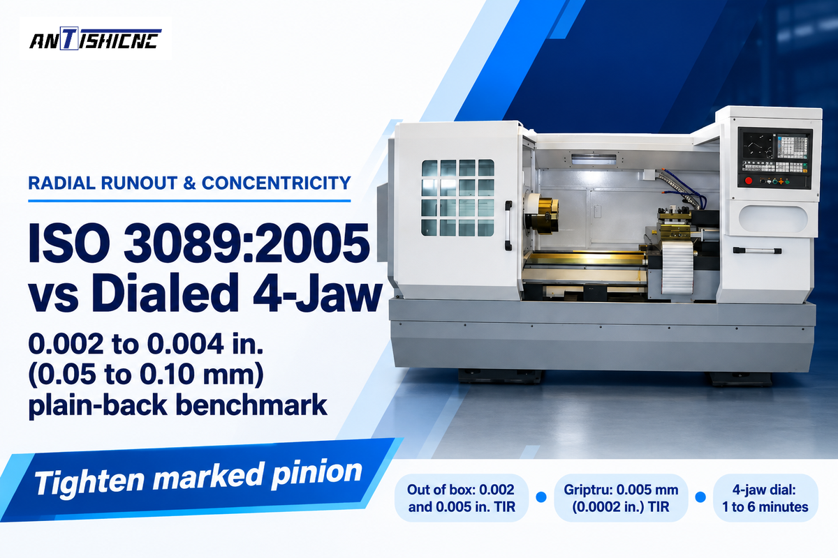
A standard plain-back 3-jaw self-centering scroll chuck typically displays 0.002 to 0.004 in. (0.05 to 0.10 mm) field radial runout on a ground test bar. Scroll-chuck centering error is attributed to scroll geometry, jaw fit and wear, mounting eccentricity and deformation under clamping load; pinion backlash mainly accounts for lost motion when the key reverses direction.
The 0.002 to 0.004 in. field radial runout benchmark for a standard 3-jaw scroll chuck is distinct from international standard test scopes and OEM guarantees:
- Official ISO 3089:2005 specifies static geometrical acceptance tests for manually operated self-centring chucks with two or more one-piece hard jaws. The tests check radial runout on precision test bars and axial face camming. Field-realistic figures for brand-new standard plain-back chucks out of the box land between 0.002 and 0.005 in. TIR.
- Scroll runout varies across the clamping diameter range. Shop use wears the mid-travel scroll spiral where common bar sizes sit. Clamping a different diameter moves the jaws onto an unworn section of the scroll plate and shifts the centerline. AUTO STRONG engineering notes warn that bell-mouthed jaw guideways, adapter-plate runout, or spindle bearing play also cause runout even when jaw teeth look clean.
- Single-clamping rigid bar work is different from second-operation rechucking. On rigid solid bar stock machined completely in one clamping, turning the outside diameter, boring the inside diameter, and parting off makes concentric features once radial depth of cut cleans up the bar. Chuck runout can cause geometric errors during rechucking or machining relative to an existing datum. It can also produce uneven wall thickness or incomplete cleanup when an unmachined surface remains on the finished part.
- Micro-adjustable scroll chucks trim mounting eccentricity. According to the Pratt Burnerd Griptru manual, the mounting register must have no more than 0.005 mm (0.0002 in.) full indicator movement. Three fine-pitch radial screws shift the chuck body over its adapter boss. Pratt Burnerd reports 0.005 mm TIR repeatability on duplicate round parts for its Griptru chucks after the specified mounting and centering adjustments. Always tighten the chuck through the single marked pinion socket.
- Dialing a 4-jaw chuck is bounded by spindle and part form error. On a 4-jaw independent chuck, a machinist coordinates opposing jaw screws to align a workpiece over 1 to 6 minutes (or roughly 1 minute to bring a round datum within 0.001 in.). Dialing the indicator close to zero minimizes indicated runout at the measured plane, but the reading combines setup eccentricity, workpiece form error and spindle radial motion error. For deeper datum control strategies, check out our article on tight-tolerance machining.
Workpiece shape guide: hexagonal, rectangular, and eccentric stock
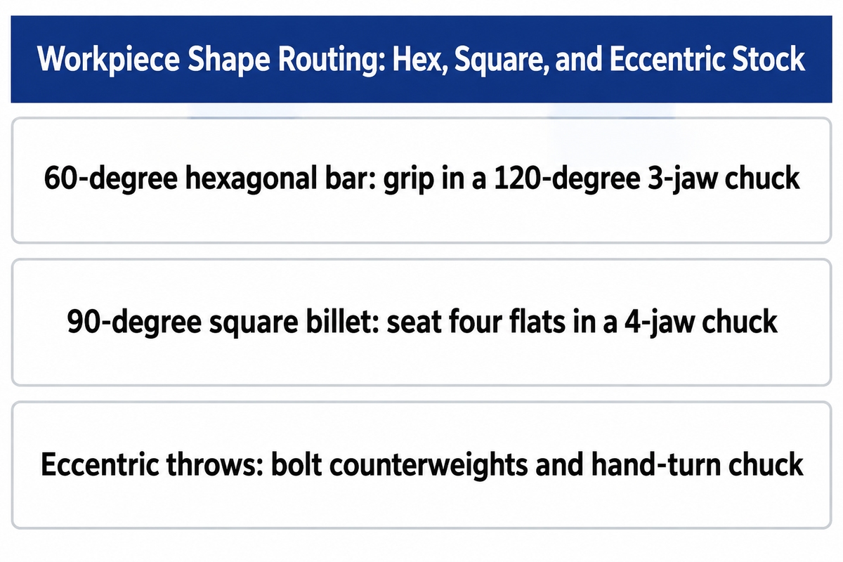
A 3-jaw chuck with jaws spaced 120 degrees apart grips round bar and regular hexagonal stock, while a 4-jaw independent chuck with jaws spaced 90 degrees apart accommodates square billet, rectangular blocks, rough castings, and off-center crankshaft journals. Both chuck styles serve distinct roles across manual and CNC turning setups.
Why is a 4-Jaw Chuck Essential for Machining Square, Rectangular, or Irregularly Shaped Workpieces?
A 4-jaw independent chuck is necessary for square, rectangular and irregular workpieces because its four jaws are at 90 degree intervals and adjust independently to different radial distances. Square and rectangular bars have four flat faces at 90 degree intervals. Each jaw seats squarely against a flat face without slipping. For rectangular blocks, asymmetric valve bodies, or eccentric shafts, independent leadscrews enable you to offset one pair of opposing jaws while centering the other pair. That adjustment positions any chosen feature directly on the lathe spindle axis.
Observe the following rules of geometry and balance when routing stock across the shop floor:
- Regular hexagonal stock belongs in a 3-jaw chuck. Regular hexagonal bar has six flats spaced at 60-degree exterior intervals. Three jaws spaced at 120 degrees land flat against every second hex face and distribute clamping force evenly. If you put hexagonal stock into a 90-degree 4-jaw chuck, two opposing jaws contact flat faces while the perpendicular pair pinches across angled hex corners. This discrepancy results in jaw slip under heavy turning loads.
- Three 120-degree jaws can’t align with four 90-degree flat faces. Attempting to grip square bar in a 3-jaw scroll chuck leads to uneven corner contact that side-loads the master jaw guideways and risks ejecting the workpiece.
- Eccentric turning requires counterweights, clearance checks and aligned tailstock support. When machining offset cam lobes or automotive CNC machining crankshaft throws in a 4-jaw independent chuck, the displaced center of mass generates centrifugal vibration. Bolt the counterweights opposite the heavy throw and reduce spindle RPM. Before starting the motor, turn the chuck a full revolution by hand to check clearance. For offset turning, a tailstock live center can support the workpiece when its center hole is aligned with the intended turning axis and the setup provides clearance for the center.
Clamping force and thin-wall tubing distortion: 3-point vs 4-point
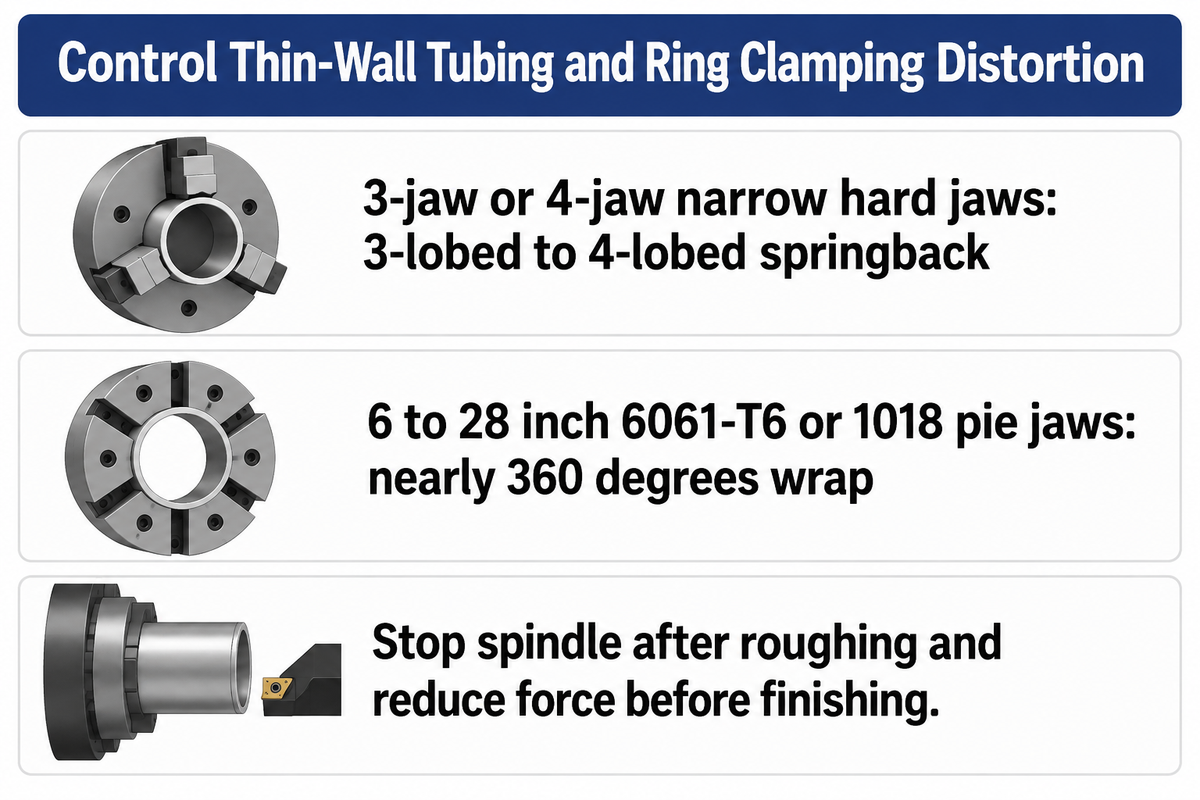
Thin-walled tubing or bearing rings clamped between three narrow hard jaws undergo elastic three-lobed deformation and spring back out of shape when released. Lower clamping force and a larger circumferential contact area can reduce clamping distortion when the remaining grip securely resists the cutting loads. Otherwise, distortion can be significant.
“suitable for thin-walled or irregular shaped parts, wrap-around pie jaws enable complete gripping while distributing pressure evenly throughout the workpiece” – Modern Machine Shop (Chuck Jaws Grip Thin-Walled Parts)
Some machinists believe that thin-wall distortion is eliminated when switching from a 3-jaw chuck to a 4-jaw independent chuck. This isn’t the case. University machining research (including Leibniz University Hannover IFW deformation studies and bearing-ring turning experiments on SAE 52100 steel rings) establishes an important boundary. Both 3-jaw and 4-jaw narrow hard-jaw chucks can cause excessive radial deformation on low stiffness rings, even at moderate clamping forces. Switching from three narrow jaws to four narrow jaws shifts the elastic deflection mode from three-lobed to four-lobed, rather than eliminating it. Radial jaw clamping, cutting-wall deflection, and the release of internal residual stress all contribute to the final state of thin-wall sleeves, bushings and repair housings.
To hold roundness on thin-wall sleeves, bushings and repair housings:
- Install wrap-around bored pie jaws on a 3-jaw chuck. As reported by Modern Machine Shop, 6 to 28 inch pie-shaped soft jaws made from 6061-T6 or A319 aluminum (or 1018/1050 mild steel) encompass nearly 360 degrees of the part circumference. Boring the pie jaws to match the tubing diameter converts concentrated point loads into broad radial support.
- Stage roughing and finishing clamping force carefully. After roughing, stop the spindle before reducing clamping force. For a manual chuck, loosen and reclamp at a lower force that resists finishing loads. The workpiece must be securely seated and concentric prior to the finishing pass.
- Use split sleeves or axial clamping for highly flexible rings. Highly flexible rings can also be clamped against a supported datum face, avoiding radial jaw loading. Either method can distort the ring.
When repetitive setup jobs require bored soft jaws over a 4-jaw
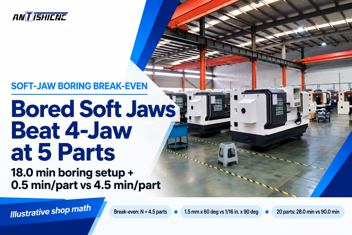
For one-off parts, dialing a 4-jaw independent chuck takes only a few minutes and no custom tooling. Boring soft jaws saves total batch time, especially if the cumulative per-part handling time saved exceeds the initial jaw-boring time. Properly preloaded soft jaws also hold 0.0005 to 0.0015 in. (0.013 to 0.038 mm) rechucking repeatability.
What are the Differences in Setup Time and Operator Skill Required for Each Chuck Type?
A standard 3-jaw scroll chuck requires minimal operator skill on raw bar work because turning a single pinion centers the bar in 10 to 30 seconds. A 4-jaw independent chuck is slower per piece. It requires an experienced machinist to read a dial indicator while coordinating opposing jaw screws over 1 to 6 minutes per workpiece. Boring soft jaws on a 3-jaw chuck shifts the skill investment upfront. The machinist spends 15 to 20 minutes preloading and boring the jaw pocket once, then loads every subsequent part in 10 to 20 seconds with automatic concentricity.
Note that ISO 3442-1:2005, ISO 3442-2:2005, and ISO 3442-3:2007 (which replaced withdrawn ISO 3442:1991) standardize the mechanical tongue-and-groove and serrated interface dimensions between master jaws and top jaws. Achieving 0.0005 to 0.0015 in. rechucking accuracy depends on three shop-floor boring rules documented across Practical Machinist soft-jaw threads:
- Match the preload plane to the production clamping plane. With the master jaws in place, there’s slight clearance and tilt with the guideway under load. Soft jaws bored without preload can tilt or deflect when subsequently clamped, resulting in uneven contact and loss of concentricity. Preloading at the back while gripping production parts at the front changes the jaw loading moment and can cause taper, uneven contact, and rechucking runout.
- Support the preload fixture at the gripping plane and match clamping force. Support the preload fixture securely at the production gripping plane and bore with the same clamping direction and force used for the workpiece. On manual chucks, always tighten at the single marked master pinion socket during both boring and production CNC turning operations.
- Never mix metric and inch jaw serrations. Verify whether your master jaws use 1.5 mm x 60 degree metric serrations (common on Asian and European power chucks) or 1/16 in. x 90 degree inch serrations. Bolting mismatched pitch angles together strips serration teeth under cutting loads.
Soft-Jaw Boring vs 4-Jaw Dial-In Break-Even Comparison
To face and bore a second-operation datum to 0.001 in. TIR on a batch of round blanks, compare two shop setups:
- Option A (4-Jaw Independent Chuck) has initial chuck mount = 0 min (already mounted) and manual dial-indicator truing and clamping per part = 4.5 min/part.
- Option B (3-Jaw Chuck with New Bored Soft Jaws) has bolting on soft jaws, setting the preload ring, and boring the pocket = 18.0 min one-time setup , with per-part clamp and unclamp = 0.5 min/part . Cycling time between bored pockets is approximately 0.5 minute per part.
Break-Even Formula. Total time equals at batch quantity N where 18.0 + 0.5N = 4.5N → 4.0N = 18.0 → N = 4.5 parts.
Operational Takeaway. Under these shop inputs, dialing the 4-jaw chuck is faster for 1 to 4 pieces (3 parts take 13.5 min in the 4-jaw vs 19.5 min to bore soft jaws). For 5 or more pieces, boring soft jaws is faster. Under these setup-time assumptions, a 20-piece batch would take 28.0 minutes total using bored soft jaws versus 90.0 minutes using manual 4-jaw indicating.
4-jaw scroll vs independent metal and woodworking chuck traps
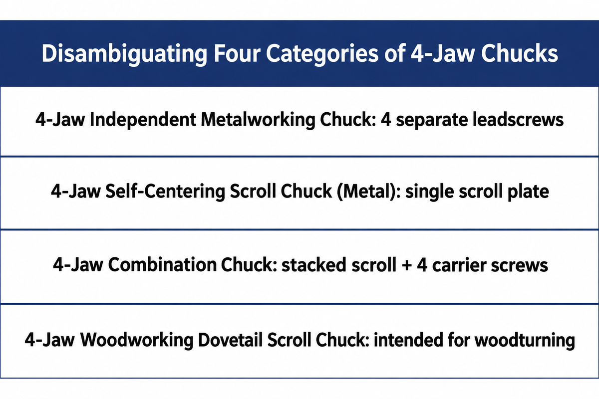
Not all 4-jaw chucks have independent jaws. Machinists and buyers must distinguish between 4-jaw independent metalworking chucks, 4-jaw self-centering scroll chucks, 4-jaw combination chucks, and 4-jaw woodworking dovetail scroll chucks before placing orders. In some cases, the centering mechanism of the scroll chuck needs to be inspected to ensure it matches the required cutting task.
Why is a four-jaw self-centering chuck considered to be inefficient regardless of its time saving features during loading the workpiece?
A four-jaw self-centering scroll chuck is often considered inefficient for general metalworking bar work because four synchronized radial jaws are kinematically over-constrained on out-of-round stock. Three synchronized jaws can support reasonably round bar work, but irregular hot-rolled or forged stock can produce uneven or incomplete jaw contact. On oval bar with its major axis aligned with one jaw pair, that pair can contact first. If deformation is insufficient to bring the perpendicular pair into contact, that pair remains unloaded and the workpiece can move under cutting forces.
Because all four jaws on a 4-jaw scroll chuck lock to one internal scroll plate, the chuck can’t dial out runout or hold off-center work. It sacrifices the precision advantage of a 4-jaw independent chuck while offering no loading speed advantage over a 3-jaw scroll chuck on round bar. The table below differentiates four categories of 4-jaw chucks.
| Chuck Sub-Type | Internal Drive Mechanism | Out-of-Round Bar Contact Physics | Eccentric & Dial-In Capability | Correct Shop Application & Trap Warning |
|---|---|---|---|---|
| 4-Jaw Independent Metalworking Chuck | 4 separate perimeter leadscrews; no scroll plate | All 4 jaws tighten individually onto high and low spots | Full eccentric offset & indicator dial-in | Standard metal lathe choice for square, irregular, casting, and ultra-concentric work |
| 4-Jaw Self-Centering Scroll Chuck (Metal) | Single scroll plate drives all 4 jaws simultaneously | On oval bar aligned with one jaw pair, that pair can contact first and leave the perpendicular pair unloaded | Zero independent adjustment | Suitable for repetitive square or octagonal stock and sufficiently round bar with reliable jaw contact; matched pie jaws can improve support for thin-wall tubing |
| 4-Jaw Combination Chuck | Stacked scroll plate + 4 independent carrier screws | Can tweak individual jaws after scroll closing | Allows rapid scroll close + indicator trim | Trap: stacked mechanism increases chuck body weight and axial spindle overhang compared with a standard chuck |
| 4-Jaw Woodworking Dovetail Scroll Chuck | Scroll mechanism with dovetail or serrated wood jaws | Grips tenons or expands in mortises | No independent jaw adjustment | Intended for woodturning; spindle compatibility alone does not establish suitability for metal-cutting loads |
Spindle mounts, bore limits, and RPM checks every machinist needs
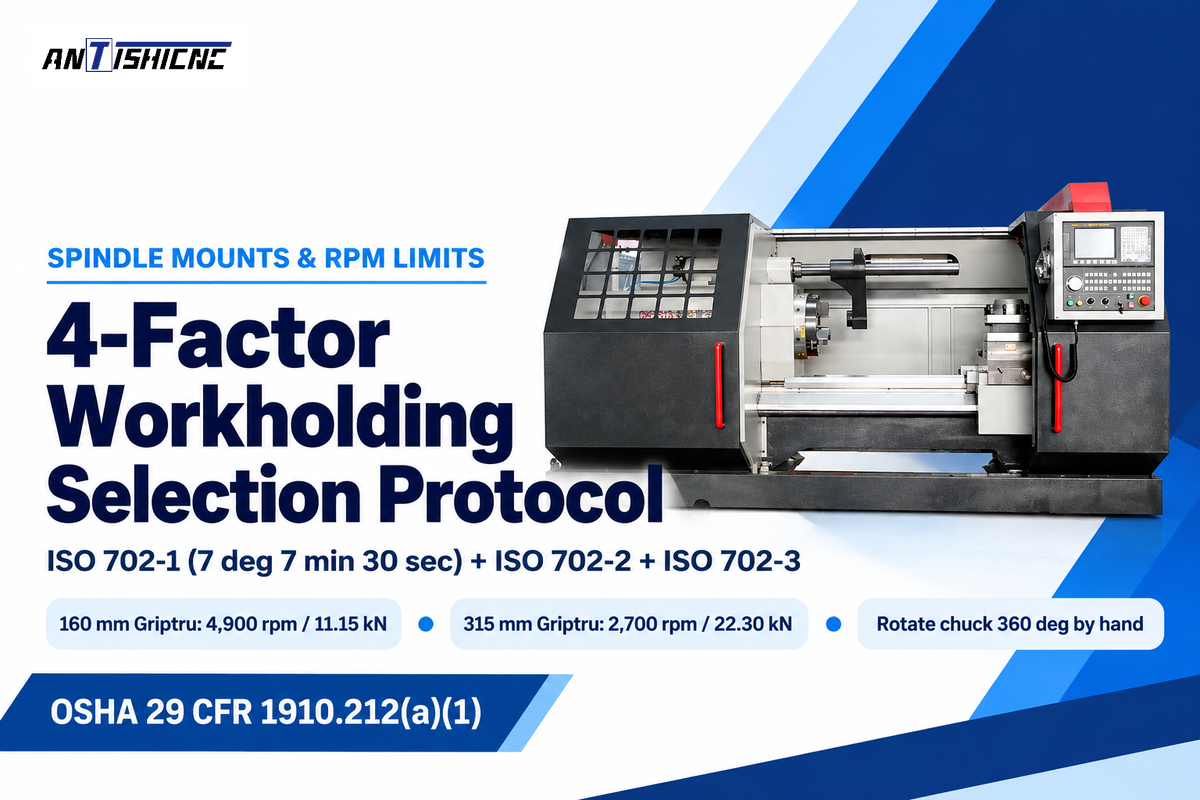
Prior to ordering a 3-jaw or 4-jaw chuck, verify the ISO 702 spindle-nose interface, usable bar passage through the drawtube and rear guard, and extended-jaw clearance over the cross-slide. Always check the manufacturer’s permissible speed for the selected chuck and jaw configuration on your lathe.
Execute this 4-Factor Workholding Selection Protocol for every lathe chuck purchase:
- Verify the spindle nose interface across ISO 702-1, ISO 702-2, and ISO 702-3. Modern CNC and heavy engine lathes use short-taper noses under ISO 702-1:2009 (7 deg 7 min 30 sec taper, confirmed current in 2025). Other lathes use Camlock noses under ISO 702-2:2007 or DIN bayonet mounts under ISO 702-3. Under ISO 702-1, Type A1 noses carry both an inner bolt circle and an outer bolt circle, whereas Type A2 noses carry only the outer bolt circle. An A2 chuck bolts directly onto an A1 nose, while an A1 inner-bolt chuck needs an adapter plate on an A2 spindle. Camlock mounts secure and release the chuck by turning the locking cams in the spindle nose; changeover also involves handling the chuck and cleaning the mating surfaces. Under ISO 702-3 bayonet mounts, stud screws pass through keyway-style bayonet holes in a rotating lockplate ring for rapid clamping.
- Check usable drawtube bar passage and Zone 1 rear bar guarding. On CNC turning centers fitted with open-center hydraulic 3-jaw chucks, the internal rotary cylinder and drawtube reduce usable bar passage below the raw spindle bore. WorkSafe Victoria’s Zone 1 guidance calls for enclosing bar stock projecting behind the headstock. A bar feeder or support tube must provide adequate restraint against whipping and protection against contact with rotating stock. General machine guarding rules under OSHA 29 CFR 1910.212(a)(1) likewise require guarding rotating chuck projections and nip points.
- Check asymmetric 4-jaw protrusion and swing clearance. Nominal chuck diameter is measured across the chuck body, not across extended jaws. When you offset a casting in a 4-jaw independent chuck, one leadscrew and jaw can protrude well beyond the chuck body perimeter. Always turn the chuck 360 degrees by hand before turning on the motor to confirm the protruding jaw clears the bed ways, cross-slide, and safety guard.
- Respect chuck body, jaw mass, and centrifugal RPM limits. ISO/WD 16156 is an edition 2 working draft under development (entering Stage 20.20 draft study in October 2026) for workholding chuck design safety, while published safety rules address centrifugal grip loss. Centrifugal force on chuck jaws increases with the square of spindle speed (patents WO1991003348A1 and CN201016687Y). The Grey cast-iron manual chucks carry lower peripheral speed limits compared to the forged steel powered chucks. In the Pratt Burnerd Griptru manual, a 160 mm chuck is rated to 4,900 rpm in precision grade (3,500 rpm standard) with 11.15 kN per-jaw static grip at 75 Nm input torque. A 315 mm Griptru chuck drops to 2,700 rpm precision (2,300 rpm standard) with 22.30 kN per-jaw grip at 203 Nm torque. Explore compatible metal turning lathes to match spindle power and speed safely.
| Workpiece Shape Category | Lathe Series & Machine Class | Spindle Bore & Passage Verification | Recommended Chuck Type & Jaw Style | Critical Setup & Safety Check |
|---|---|---|---|---|
| Round Bar Stock (First-Op) | ANTISHICNC C6163B Universal Lathe (630 mm bed swing) | 104 mm spindle bore; enclose rear bar projection | 315 mm 3-jaw self-centering scroll chuck (numbered 1-2-3 hard jaws) | Verify 8.5 to 800 r/min speed setting and remove chuck key immediately |
| Heavy Square Billet & Castings | ANTISHICNC C6163B Universal Lathe (630 mm bed swing) | 104 mm spindle bore; chucked blank setup | 500 mm 4-jaw independent chuck with reversible stepped jaws | Dial flat faces to indicator and rotate spindle 360 deg by hand |
| Regular Hexagonal Bar Stock | Manual Engine or Horizontal CNC Turning Lathes | Match across-corners hex size to drawtube bore | 3-jaw scroll chuck (120-deg jaws seat on alternate 60-deg flats) | Avoid 4-jaw chucks that pinch opposing hex corners unevenly |
| Precision Duplicate Round Blanks | Toolroom Engine Lathes | Mounting register within 0.005 mm (0.0002 in.) FIM | Micro-adjustable 3-jaw scroll chuck (Pratt Burnerd Griptru 160 to 315 mm) | Tighten exclusively at marked “0” pinion socket; respect 2,300 to 4,900 rpm rating |
| Repetitive Second-Op Turned Parts | ANTISHICNC CK6130 / CK6140 / CK6150 CNC Lathes | Confirm hydraulic drawtube bar passage in model quotation | Open-center 3-jaw power chuck with ISO 3442 serrated bored soft jaws | Support preload fixture at production gripping plane and match clamping force |
| Thin-Wall Sleeves & Bearing Rings | Manual or CNC Turning Centers | Chucked ring setup; avoid excessive radial point loads | 3-jaw chuck with 6 to 28 in. 6061-T6 or 1018 wrap-around pie jaws | Stop spindle after roughing and reduce clamping force before finishing pass |
| Eccentric Crankshafts & Cam Lobes | Manual or CNC Lathes with Counterweight Clearance | Offset axis setup; align tailstock center hole to turning axis | 4-jaw independent metalworking chuck with counterweight plates | Keep imbalance loads within spindle limits and verify jaw swing clearance |
| Long Oil-Country Tubulars & Pipe | ANTISHICNC QK1313 / QK1319 / Q1327 Pipe Lathes | 135 to 280 mm hollow spindle bore across series | Coaxial front-and-rear double chucks (4-jaw independent or power chucks) | Support pipe projecting beyond rear chuck to prevent whipping |
Specifying 3-jaw and 4-jaw chucks on manual and CNC turning lathes
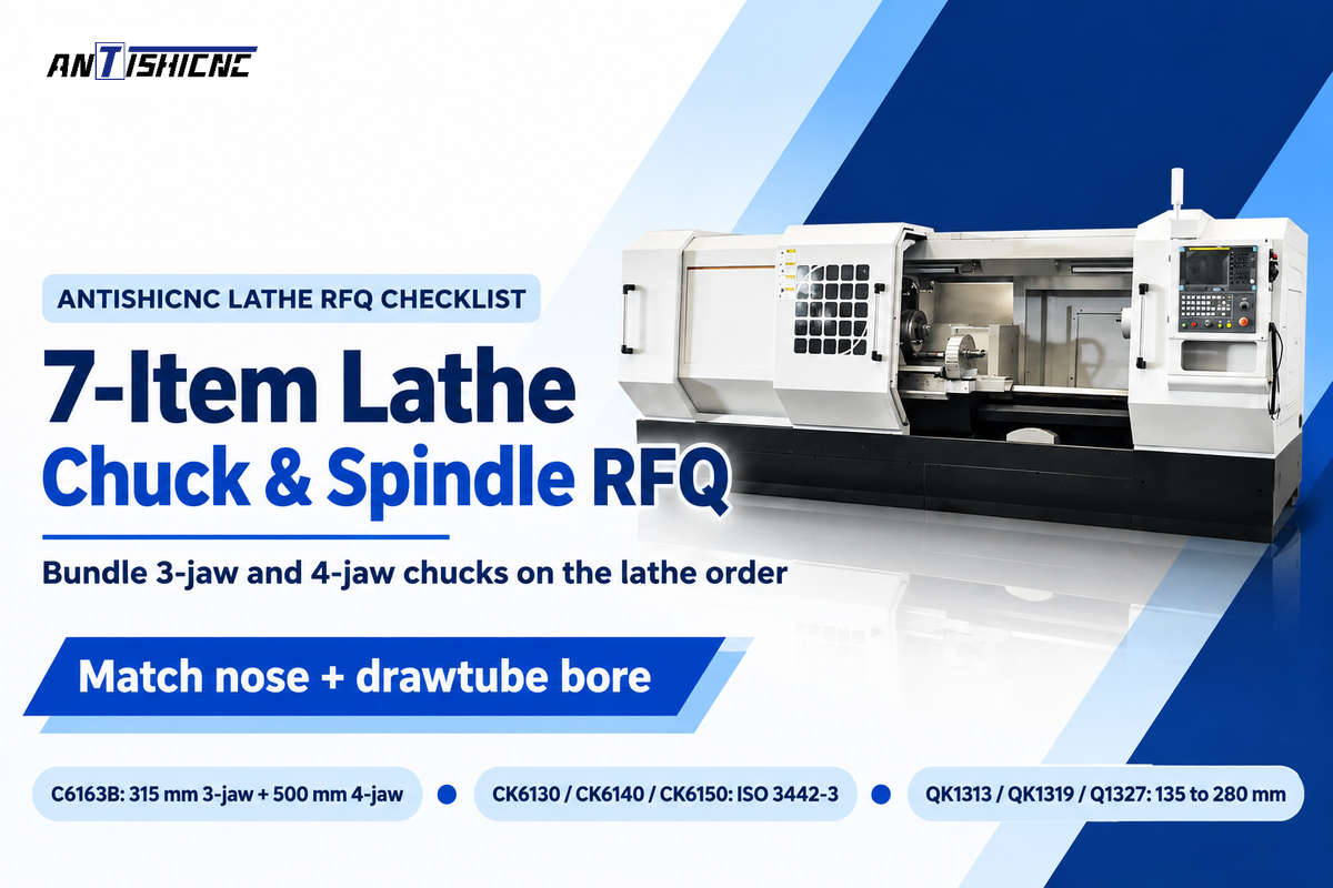
A 3-jaw chuck and a 4-jaw chuck can be complementary purchases for an industrial machine shop. Combining the two chuck types on the first lathe purchase order ensures the spindle adapter plates, drawtube threads and safety guards are in alignment from day one.
- Manual toolroom and maintenance engine lathes profit from a dual-chuck bundle. For example, on universal manual lathes like the ANTISHICNC C6163B, use a 315 mm 3-jaw scroll chuck for daily round shaft work. Couple it with a 500 mm 4-jaw independent chuck for square blocks, repair weldments and eccentric shafts. With a D1 Camlock spindle nose, the operator is able to release locking cams in the spindle nose and swap chucks with a hoist cradle.
- Production CNC turning centers pair hydraulic 3-jaw power chucks with soft jaws. On CNC lathe machines such as the CK6130, CK6140, or CK6150, specify a forged-steel open-center 3-jaw hydraulic power chuck from OEMs such as Kitagawa, Schunk, Röhm, Bison, or Auto Strong. Include spare sets of ISO 3442-3 serrated soft jaws and a preload boring ring. Add a manual 4-jaw independent chuck on a matched adapter plate if your shop runs low-volume rectangular castings.
- Large-Bore Pipe & Oilfield Lathes: ANTISHICNC lists coaxial front-and-rear chucks on the QK1313, QK1319, and Q1327, with spindle bores from 135 to 280 mm. These chucks grip and center long tubulars, but unsupported pipe projecting beyond the rear chuck can still whip. Explore pipe threading lathes to match rear support stands to your pipe length.
7-Item Lathe Chuck & Spindle RFQ Checklist
When requesting a factory quotation from ANTISHICNC for a manual, CNC, or pipe threading lathe package, include the seven workholding parameters. Our engineers use them to match the spindle nose, drawtube bore, and chuck jaws accurately:
- Cross-sections of materials such as round bar, hexagonal stock, square billet, rectangular blocks, or asymmetrical castings.
- Clamping diameter and bar-thru requirement, including minimum and maximum outer/inner grip diameters, plus required drawtube bar passage (mm).
- Accuracy Requirements: Specify measurement location for first operation TIR and rechucked setups, separate roundness requirements, and minimum wall thickness.
- Workpiece mass and overhang length, indicating maximum part weight (kg), axial length, and whether tailstock live-center or steady-rest support is required.
- Target spindle RPM and cutting mode, discerning continuous high-speed finishing vs. heavy interrupted roughing cuts.
- Preferred spindle nose standard, such as ISO 702-1 Type A1/A2, ISO 702-2 Camlock D1, or ISO 702-3 bayonet mount.
- Auxiliary tooling bundle, such as extra ISO 3442 serrated soft-jaw sets, wrap-around pie jaws, boring preload ring, or a matched 4-jaw independent chuck.
Frequently asked questions
Can you hold hexagonal bar stock in a 4-jaw independent chuck?
A standard 90-degree 4-jaw chuck can’t grip regular 60-degree hexagonal flats symmetrically. Two jaws grip flat faces, while the other two jaws pinch at the corners of the hexagon. This uneven contact creates a potential for the pinch to release and slip. A 120-degree 3-jaw scroll chuck or a hexagonal collet holds regular hex bar far more securely and faster.
Why must soft jaws on a 3-jaw chuck be bored under clamping preload?
Micro clearances remain in guideways when jaws close. Soft jaws bored without preload may shift or tilt under clamping load, resulting in localized or tapered contact instead of contact along the intended grip length. A preloaded fixture in the production gripping plane can reduce jaw lifting by applying pressure to each jaw in the intended clamping direction.
Does an A2-6 or D1-6 lathe spindle mount mean a 6-inch chuck diameter?
No, the number 6 designates the standardized ISO 702 spindle-nose taper gauge size (106.375 mm gauge diameter), not the chuck body diameter. An A2-6 or D1-6 spindle nose routinely mounts 200 mm (8 in.), 250 mm (10 in.), or 315 mm chucks. Always verify that the selected chuck fits within the lathe swing and bearing limits.
Which chuck has reversible hard jaws: 3-jaw or 4-jaw?
Four-jaw independent chucks have reversible stepped jaws that can be unthreaded and reversed 180 degrees. One-piece 3-jaw scroll jaws have directional spiral teeth that require separate inside and outside jaw sets; chucks with two-piece jaws allow suitable top jaws to be reversed independently of the master jaws.
How do machinists counterbalance off-center crankshafts or castings in a 4-jaw chuck?
Bolt counterweight plates opposite the heavy offset throw on the chuck face or faceplate before cutting. Before starting the motor, turn the chuck a full 360 degrees by hand, to check that protruding jaws and counterweights clear the bed ways, cross-slide, and safety guard. For offset turning, a tailstock live center can support the workpiece when its center hole is aligned with the intended turning axis and clearance permits. Reducing spindle speed lowers the centrifugal force from an eccentric workpiece. The operating speed must also keep imbalance loads within spindle limits and retain a secure workpiece and counterweight.
Are 4-jaw chucks made of cast iron or forged steel for high RPM?
A forged alloy-steel 4-jaw chuck is recommended for high RPM; medium-duty manual 4-jaw chucks commonly use grey or nodular cast-iron bodies with lower RPM ceilings. Always confirm the manufacturer’s permissible speed for the selected chuck and jaw configuration.
What workpiece and spindle details should you send when specifying lathe chucks?
Send your part drawing showing raw and finished cross-sections, minimum wall thickness, and separate roundness requirements. State your target radial TIR at a specified measurement location for first-operation and rechucked setups. Include maximum workpiece mass, overhang length, required through-bar diameter versus chucked blank size, target spindle speed, and typical batch quantity. Specify your preferred spindle nose standard such as ISO 702-1 Type A1 or A2, ISO 702-2 Camlock D1, or ISO 702-3 bayonet mount. Providing these parameters lets the lathe manufacturer match the spindle bore, hydraulic drawtube, jaw style, and guard clearance together.
Engineering Review & Compliance Note: Check the maximum safe spindle speed against the minimum rating of the chuck body, top jaws and workpiece balance before starting the spindle. Request a model-specific technical quotation from the lathe manufacturer for custom workholding packages.
References & Sources
- International Organization for Standardization (ISO). ICS 25.060.20: Workholding spindles and chucks (ISO 3089:2005, ISO 702-1..4, ISO 3442-1..3, ISO 19719:2010).
- International Organization for Standardization (ISO). ISO 702-1:2009, Tools, Definitions of connecting dimensions of spindle noses and work holding chucks, Part 1: Conical connection.
- International Organization for Standardization (ISO). ISO 702-2:2007, Tools, Definitions of connecting dimensions of spindle noses and work holding chucks, Part 2: Camlock type.
- International Organization for Standardization (ISO). ISO/WD 16156 (Edition 2 working draft under development), Tools, Safety, Safety requirements for the design and construction of work holding chucks.
- WorkSafe Victoria (Government of Victoria, Australia). Safe use of metal turning lathes (Zone 1 Stock Bar & Zone 3 Chuck Guarding and Selection).
- U.S. Occupational Safety and Health Administration (OSHA). 29 CFR 1910.212, General requirements for all machines (Rotating Chuck & Nip-Point Guarding).
- Pratt Burnerd International. Griptru Micro-Adjustment Scroll Chuck Operating Instructions & Technical Specifications (0.005 mm Concentricity, Torque & RPM Tables).
- Modern Machine Shop. Chuck Jaws Grip Thin-Walled Parts (6 to 28 in. Wrap-Around Pie Jaws in 6061-T6 Aluminum and 1018 Steel).
- Industrial Monitor Direct. 3-Jaw Chuck Runout: Expected Accuracy Benchmarks, Single-Setup vs Rechucking, and Field Repair Methods.
- AUTO STRONG (Di Chun Iron Work Co.). When Should You Replace Lathe Chuck Jaws? 7 Signs of Wear, Accuracy Loss, and Safe Speed Boundaries.
- US Shop Tools. Complete Guide to Lathe Chuck Jaws Selection, Metric vs Imperial Serrations (1.5 mm x 60° vs 1/16″ x 90°), and Maintenance.
- Kitagawa Corporation. Manual Chucks Lineup: Scroll Self-Centering (JN/SC) and 4-Jaw Independent (IA/IC) Chucks.
- Google Patents. WO1991003348A1 – High-Speed Conical Self-Locking Lathe Chuck Assembly and CN201016687Y – Scroll-Plate Synchronous Three-Jaw Radial Centering Device.
- SHANGHAI ANTS Machine Equipment (ANTISHICNC). C6163B Universal Lathe, CNC Lathe Technical Quotations (CK6130, CK6140, CK6150), and Q13/QK13 Dual-Chuck Pipe Threading Lathes.