





Lathe chuck types determine which workpiece cross-sections a metal lathe holds, how quickly operators load blanks, and how much bar clears the spindle. Choose a 3-jaw scroll chuck for round or hex bar, and use a 4-jaw independent chuck for square or offset parts. Specify a 6-jaw or collet chuck to limit thin-wall distortion, and fit an open-center hydraulic power chuck for automated bar feeding.
- Round and hexagonal bar: 3-jaw scroll chuck or precision collet chuck matched to bar profile.
- Square billet, asymmetric castings, and eccentric journals: 4-jaw independent chuck.
- Thin-wall tubing sensitive to clamping force: 6-jaw chuck, wrap-around pie jaws, or collet chuck.
- Automated CNC bar feeding: open-center hydraulic power chuck matched to the narrowest spindle-chain bore.
- Large ferromagnetic bearing rings: radial-pole electro-permanent magnetic chuck with a flat datum face.
This document covers industrial metal turning only and excludes woodturning scroll chucks fabricated for timber lathes. All standard scopes, gripping pressure rules, and machine bore figures cited below reference their published ISO records or supplier datasheets.
Six lathe chuck types compared by workpiece shape and actuation
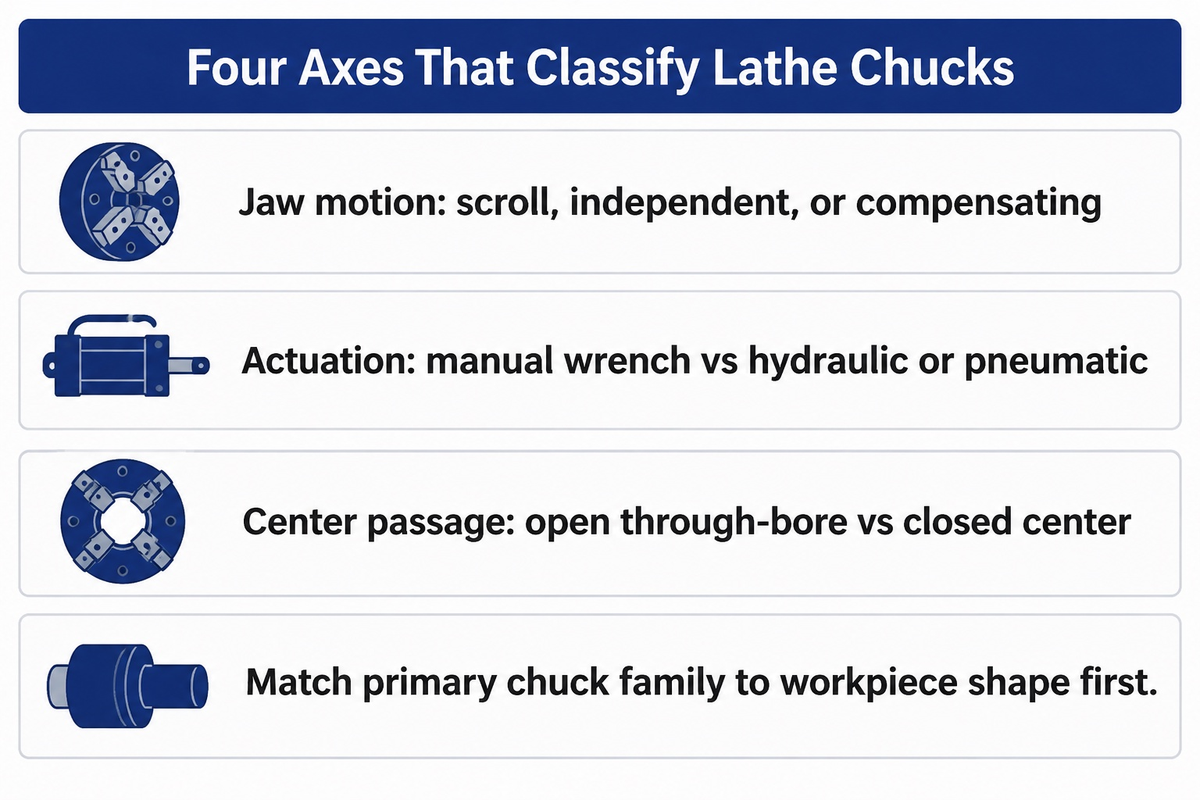
There are six main families of metalworking chucks: scroll, independent, collet, hydraulic power, magnetic and specialty multi-jaw chucks. The ten shop configurations in the comparison table below correspond to the six families of chucks. Jaw count, synchronous or compensating motion, manual or power actuation, and open or closed centers can combine on the same spindle.
A rotating chuck is a workholding device mounted on the spindle nose that spins with the workpiece to transmit cutting torque. Stationary indexing chucks bolted to milling tables don’t face centrifugal grip loss. Considering a rotating chuck as a complete clamping device prevents mismatched adapters or drawtubes. For the workpiece on your part print, consider a 3-jaw scroll chuck for round or hex stock before pricing top jaws. For square or offset parts among different types of lathe chucks, consider a 4-jaw independent chuck.
What is the difference between a manual chuck and a power chuck?
A manual chuck tightens when an operator turns a T-handle wrench, or chuck key, in a scroll pinion or screw with the spindle stopped. A typical CNC power chuck opens and closes its jaws through a drawtube or drawbar driven by a rear-mounted hydraulic or pneumatic cylinder.
Chucks with a mounted or integrated cylinder also serve specialized spindles, and clamp time depends on the jaw stroke and the flow of the fluid. Manual chucks fit toolroom lathes, repairs, and long shafts where loading takes far less time than cutting. With computer numerical control turning centers, hydraulic or pneumatic actuation regulates clamping pressure and links to bar feeders or robots. Manual actuation is suitable for toolroom jobs, and power actuation for CNC batches. Match the type of chuck to part geometry.
| Configuration & Six-Family Group | Actuation & Kinematics | Best Workpiece Shapes | Center Bore & Accuracy Boundary |
|---|---|---|---|
| 3-jaw universal chuck (Family 1: Scroll) | Manual scroll plate driven by bevel pinion | Round bar and equilateral hex stock | Through-hole bore; one-piece-jaw static tests in ISO 3089:2005 |
| 4-jaw self-centering chuck (Family 1: Scroll) | Synchronous four-slot scroll plate | Square bar, round bar, and octagonal stock | Through-hole bore; rapid centering for symmetrical four-sided stock |
| 4-jaw independent chuck (Family 2: Independent) | Four separate manual lead screws | Square stock, rectangular blocks, offset cams | Through-hole bore; dialed to indicator resolution on each part |
| 5C / 16C pullback collet (Family 3: Collet) | Drawtube pulls tapered collet into spindle sleeve | Precision round, hex, or square bar matched to collet bore | 360-degree grip; slight axial Z-shift when bar diameter varies |
| Dead-length collet chuck (Family 3: Collet) | Tapered sleeve pushes over stationary collet | Second-operation blanks and sub-spindle transfers | Through-bar capable; holds axial Z-shoulder position fixed |
| Open-center power chuck (Family 4: Hydraulic power) | Rear rotary hydraulic cylinder and hollow drawtube | Continuous CNC bar-fed shafts, bushings, and flanges | Usable bar limited by narrowest bore across chuck, tube, spindle, cylinder, and liners |
| Closed-center power chuck (Family 4: Hydraulic power) | Power actuation with no through-bar passage | Chucked billets, forgings, and heavy shaft work | No bar passage; wedge slideways need sealing at jaw slots against chips and coolant |
| Electro-permanent chuck (Family 5: Magnetic) | Electrical pulse magnetizes radial permanent poles | Ferromagnetic bearing rings and large flat discs | OD, ID, and face access; requires flat contact face and ferromagnetic part with adequate area and thickness |
| 6-jaw scroll or compensating (Family 6: Specialty multi-jaw) | Synchronous scroll or paired floating levers | Thin-wall tubing (scroll) or rough castings (compensating) | Six contact points spread load; scroll style needs round gripping surfaces |
| 2-jaw or combination chuck (Family 6: Specialty multi-jaw) | Screw, wedge-hook, or scroll plus four screws | Valve bodies, elbow fittings, eccentric castings | Formed soft jaws grip odd bosses; combination body repeats offset batches |
Turning departments running different types of lathe machines often stock two or three types of lathe chuck bodies per spindle size. The shape of the workpiece determines the primary clamping family before top jaw profiles enter the quote.
3-jaw scroll vs 4-jaw independent chucks: runout and setup speed
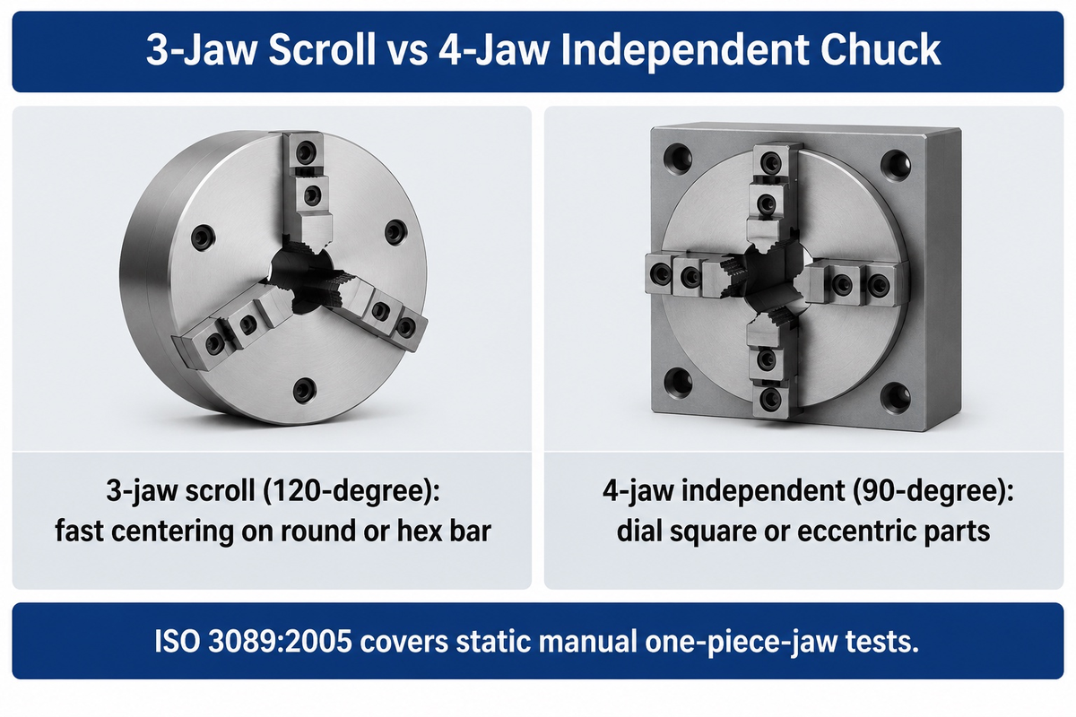
A self-centering 3-jaw scroll chuck clamps round or hexagonal bar in seconds with one wrench turn. Conversely, a 4-jaw independent chuck takes several minutes per piece to align square, asymmetric or eccentric workpieces with a dial indicator. Choose the three-jaw chuck for fast bar roughing, and the 4-jaw chuck when concentricity or intentional offset outweighs setup time.
A bevel pinion in a manual scroll body turns a spiral plate that moves three jaws radially together. Scroll teeth wear fastest in a shop’s most common clamping diameter band, which shifts centering repeatability elsewhere on the spiral. On manual scroll chucks with three pinions, veteran machinists on Practical Machinist mark one primary socket for tightening. Tightening only that marked pinion holds roughly 0.002 in TIR on hard jaws and about 0.0005 in TIR on bored soft jaws.
What’s the difference between a 3-jaw and 4-jaw manual chuck?
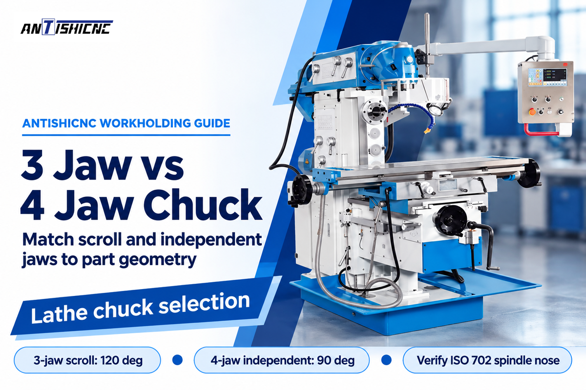
A 3-jaw manual chuck drives three jaws simultaneously at 120-degree spacing through one geared scroll plate to center round or hex stock fast. A 4-jaw manual independent chuck moves each jaw on its own screw or pinion at 90-degree spacing to center irregular blocks or offsets.
Rules on workplace safety reinforce this geometric split. WorkSafe Victoria’s metal turning lathe guidance instructs shops to mount four-jaw chucks for irregularly shaped workpieces and keep three-jaw chucks on round stock. The same guidance calls for spring-loaded self-ejecting keys or interlocked chuck guards so a wrench never stays in the pinion socket.
In the ISO/TC 39/SC 8 workholding catalogue, ISO 3089:2005 covers static geometrical tests for manually operated self-centering chucks with one-piece jaws, defining static accuracy and precision at rest. A chuck that passes static test-bar runout in an inspection room can still lose dynamic gripping force at high spindle speed and exhibit nonzero runout on rough hot-rolled bar. For precise centering on second-operation shafts, machinists either dial a 4-jaw chuck to indicator resolution or bore preloaded soft jaws (Modern Machine Shop).
6-jaw chucks and collet chucks for thin-wall distortion and repeatability
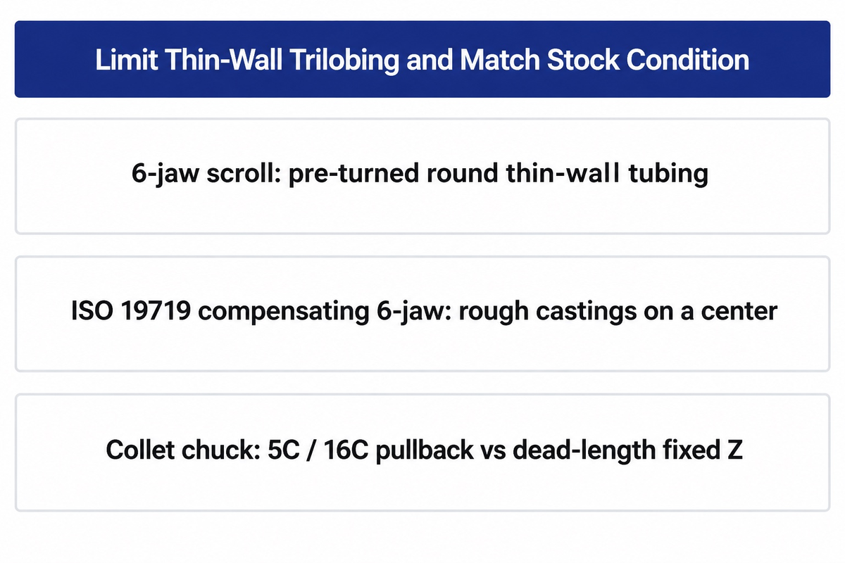
Too much three-point clamping force can lead to three-lobed distortion on thin-wall tubing and bearings. Proven workholding solutions that can reduce the chance of distortion include six-jaw chucks, wrap-around pie jaws, and collet chucks. Match the holder to raw stock roundness and axial Z-length tolerance instead of assuming extra jaws always cut runout.
Elastic trilobing takes a different mechanical path than simple off-center runout. The boring of a thin cylindrical sleeve while it’s distorted by excess three-jaw chuck force creates a round hole under a load. After the chuck pressure is released, elastic recovery can create three-lobed out of roundness beyond tight bore limits. Tonfou’s jaw engineering guide shows that custom-machined soft jaws spread contact area and clamping pressure to reduce deformation and surface marks. In clamping cycle speed, a synchronous 6-jaw chuck can match a 3-jaw chuck.
Still, a synchronous 6-jaw scroll chuck suits pre-turned, round, consistent gripping surfaces best. As machinist Forrest Addy notes on Practical Machinist, scale or out-of-round stock leaves some jaws lightly loaded or out of contact. This gives the remaining jaws a higher clamping force, which can potentially stress the scroll. Addy also mentions that, unless relieved against deflection, deep jaw swallow can introduce an axial taper. When rough castings need six-point support, specify a paired-lever compensating 6-jaw chuck (terminology defined in ISO 19719) around a center locator.
On clean bar stock, collet chucks combine fast clamping of a few seconds per part with strong run-out and repeat accuracy. Modern Machine Shop’s collet study reports typical TIR of 0.0006 to 0.0012 in for bored soft jaws on a 3-jaw power chuck. Precision collet chucks typically hold 0.0005 in TIR or less, and Royal Products publishes 0.0002 in TIR on quick-change CNC collet assemblies. Standard 5C and 16C pullback collets draw into a spindle taper, shifting Z-length slightly as raw material diameters vary. By contrast, Forkardt Hardinge’s HQC quick-change collet system swaps collets in under 20 seconds and grips parallel to minimize Z-pullback, handling plus or minus 1/64 in (0.396 mm) bar variation below 2 inches. Confirm whether a specific collet nose uses pullback or dead-length sleeve action when planning metal lathe turning setups.
Hydraulic power chucks: open-center vs closed-center bar capacity
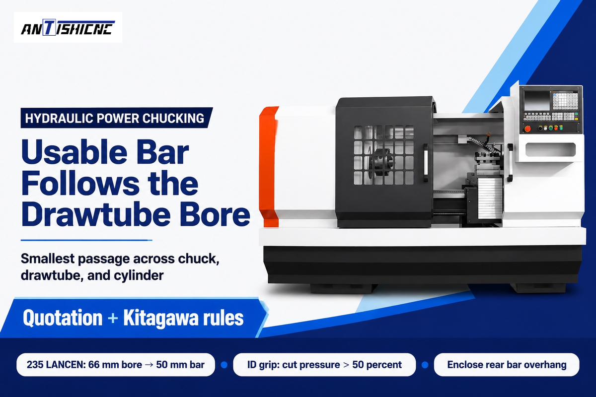
Open center hydraulic power chucks are best when bar stock is continuously fed through spindle bores. A closed-center hydraulic chuck is best for chucked billets or shaft work supported on a tailstock center. The usable bar capacity of a power chuck is always less than the raw spindle bore capacity of the lathe due to internal actuation hardware.
A rear rotary cylinder on standard CNC lathe machines pulls and pushes a hollow steel drawtube that’s threaded into the chuck wedge plunger. The actual bar capacity is restricted by the smallest bore across the spindle, rotary cylinder, drawtube, chuck body and spindle liner. Closed-center chucks have no through passage for bar feeding across a broad range of lathe spindle sizes. Protecting their internal wedge slideways from fine chips and high pressure coolant still requires effective wipers and sealing at the jaw slots.
Official ANTISHICNC technical quotations show the exact bore step-down on slant-bed CNC lathes and flat-bed models. On the 235 LANCEN slant-bed lathe, a 66 mm spindle bore pairs with a 50 mm hydraulic drawtube bore, capping fed bar at 50 mm. On the CK6150/1000 flat-bed CNC lathe, 82 mm and 130 mm spindle bores step down from 80 mm and 128 mm manual bar ratings to 65 mm and 118 mm optional drawtube bores. Passing stock through the drawtube never allows bare bar overhang behind the machine. WorkSafe Victoria Zone 1 rules require full rigid enclosure and rear support so rotating bar stock can’t whip.
Raising hydraulic gauge pressure to increase grip force on hollow parts or internal gripping can be dangerous. According to Kitagawa’s Chucks 101 manual, switching a wedge-hook power chuck from external OD clamping to internal ID expanding clamping requires reducing the hydraulic pressure by more than 50 percent. Outward wedge mechanics multiply body stress during ID grip. At the same time, Tonfou’s CNC power-chuck guide notes that if clamping force is too low, the workpiece may slip, vibrate, or move under cutting load. Long casing in the oil and gas industries requires use of a pair of front and rear chucks to grip the full pipe length.
Magnetic, combination, and two-jaw chucks for rings and valve bodies
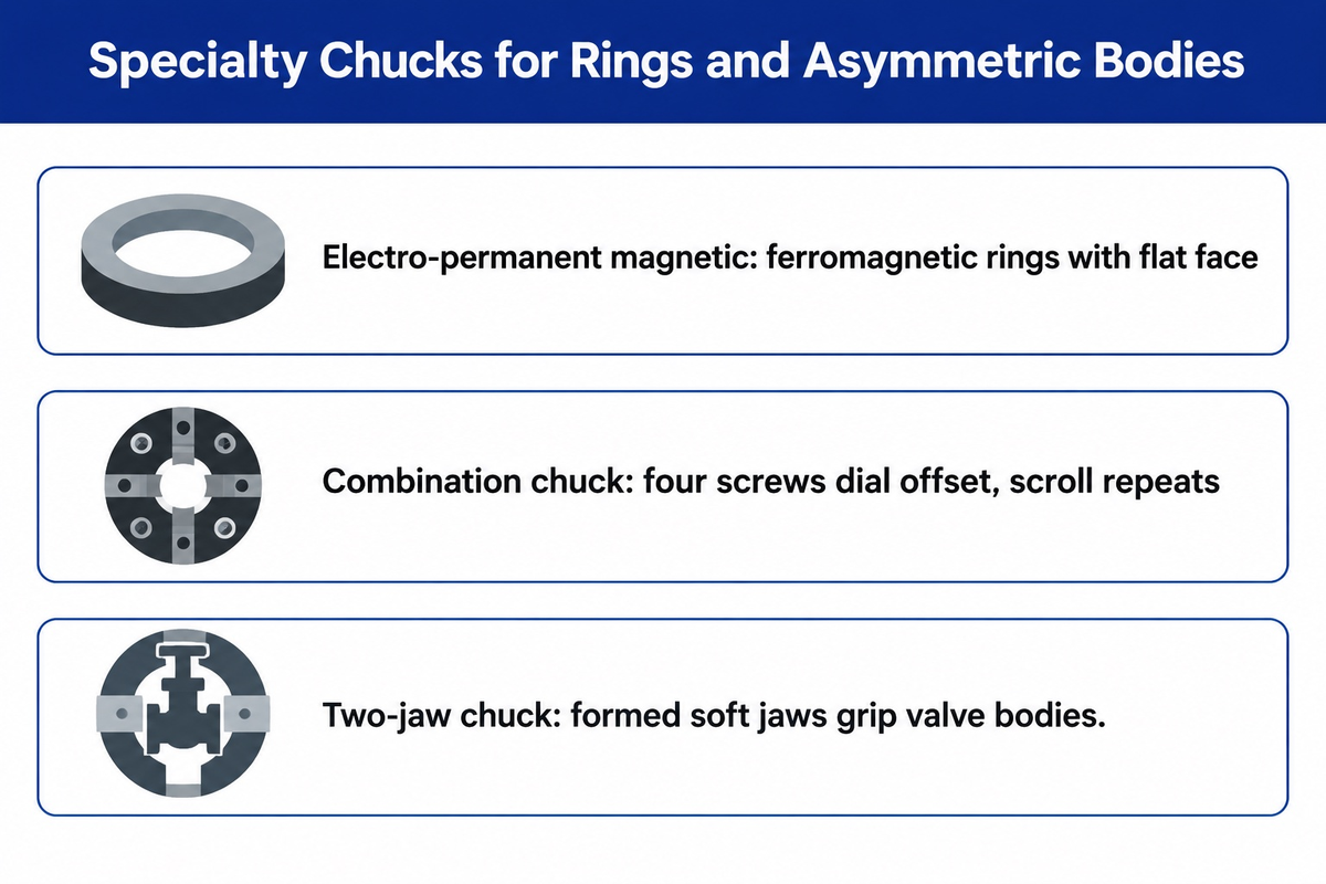
Large bearing rings, asymmetric valve bodies, and off-center castings require electro-permanent magnetic chucks, combination chucks, or formed two-jaw chucks. Each serves a particular range of applications where standard three-jaw clamping would distort thin walls and miss irregular bosses.
Radial-pole electro-permanent magnetic chucks, such as Wagner Magnete’s 1210V turning series (200 to 2,300 mm outer diameter, IP67 rated), energize internal poles with a brief electrical pulse. Power disconnects during cutting, which eliminates continuous coil heating on horizontal or vertical lathes, though cutting heat and machine heat transfer still exist. Wagner’s radial layout leaves the outer diameter, inner bore, and front face open for three-face ring turning in one clamping. HVR Magnet’s engineering notes report peak holding force per unit area up to 16 kgf/cm2 on thick low-carbon steel. Holding force drops on thin walls or hardened alloy steels, and non-magnetic 304 stainless or aluminum won’t clamp. Suitable ferromagnetic steel or cast-iron rings also need a pre-machined flat datum face against the poles.
Non-magnetic castings and irregular forgings rely on mechanical specialty chucks across batch machining processes. Combination chucks pair a self-centering chuck scroll plate with four independent radial screws for high versatility. An operator dials an eccentric casting once with the screws, then cycles the scroll to load repeat parts. Two-jaw chucks grip valve bodies and elbow fittings inside custom-milled soft-jaw cavities securely. Under WorkSafe Victoria Zone 3 controls, custom jaws require competent design without projecting catch hazards and a slow-turn cross-slide clearance check. Patent literature also adapts standard bodies: Chinese patent application CN103611948A describes 4 to 6 mm transverse wire pads in 3-jaw grooves with reverse Z-feed for slender shafts at length-to-diameter ratios of 25 or above.
Spindle nose mounts, drawtube bore, and high-RPM grip loss
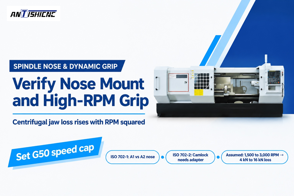
Before ordering any of the mentioned chucks mounted on the headstock, verify the four mechanical engineering checks together. Match the ISO 702 spindle nose, drawtube thread and wedge stroke, check the narrowest bar passage, and verify the rated chuck RPM against dynamic grip loss.
Published ISO 702-1:2009 documentation (reaffirmed current in June 2025) defines 7-degree 7-minute 30-second short conical spindle noses. In the ICS 25.060.20 catalogue, ISO 702-2:2007 covers Camlock stud mounts, ISO 702-3:2007 covers bayonet-disc mounts, and ISO 702-4:2004 covers cylindrical mounts. Type A1 noses machine both inner and outer bolt circles, whereas Type A2 noses provide only the outer bolt circle. Therefore, an A2-6 or A2-8 chuck bolts directly onto a matching A1-6 or A1-8 nose, while an inner-circle A1 chuck or D1 Camlock chuck needs an adapter plate on an A2 spindle. As machinists note in Practical Machinist’s spindle-nose thread, direct A2 mounting saves roughly 1 inch of overhang, while older threaded noses can unscrew under reverse torque. Per Tonfou’s power-chuck checklist, buyers must also match hydraulic cylinder stroke, pull force, and drawtube compatibility to the chuck and spindle speed.
Spindle-to-Chuck Bore Match Sheet
The reference sheet below pairs official ANTISHICNC quotation parameters for five metal turning lathes, with published ISO mounting rules and dynamic grip benchmarks. Separate raw spindle bore from hydraulic drawtube bore during chuck setup, and confirm that chuck maximum RPM exceeds expected spindle speed.
| Model or Interface | Reference Source | Spindle Bore / Taper Spec | Usable Bar & Speed Limit |
|---|---|---|---|
| CK6130 CNC lathe | ANTISHICNC technical quotation | 48 mm spindle bore; 300 mm bed swing | 45 mm rated bar; 40 mm optional drawtube; 2,500 RPM max |
| 235 LANCEN slant-bed CNC lathe | ANTISHICNC technical quotation | 66 mm spindle bore; 460 mm bed swing | 50 mm rated bar; 50 mm drawtube bore; 3,500 RPM max |
| CK6140/550 flat-bed CNC lathe | ANTISHICNC technical quotation | 48 mm or 82 mm bore configurations | 40 mm or 65 mm bar configurations; 2,000 / 1,600 RPM max |
| CK6150/1000 flat-bed CNC lathe | ANTISHICNC technical quotation | 82 mm or 130 mm bore configurations | 80 / 128 mm bar; 65 / 118 mm optional drawtube; 1,800 / 800 RPM |
| CK6160/1500 flat-bed CNC lathe | ANTISHICNC technical quotation | 130 mm spindle bore; 600 mm bed swing | 128 mm rated bar; 118 mm optional drawtube; 800 RPM max |
| ISO 702-1 Type A1 vs Type A2 | ISO 702-1:2009 | 7 deg 7 min 30 sec short taper | A1 has inner + outer bolt circles; A2 has outer circle only |
| ISO 702-2 Camlock (D1 series) | ISO 702-2:2007 | Short taper with cam-stud quick lock | Requires adapter plate to mount onto A1 or A2 flanged noses |
| Power chuck mounting runout | Kitagawa Chucks 101 | Class 12.9 socket bolts (10.9 for M22+) | 0.02 mm (0.0008 in) max radial and face runout on chuck body |
| Standard wedge-hook power chuck | Pratt Burnerd via Cutting Tool Engineering | Uncompensated heavy top jaws | Can lose over 60% of static gripping force at maximum rated RPM |
| Counterbalanced lever power chuck | Pratt Burnerd via Cutting Tool Engineering | Centrifugal weight compensation | Typically retains 80% to 90% of static gripping force at 6,000 RPM |
Assumed inputs for an illustrative high-RPM grip check: suppose an uncompensated 3-jaw power chuck delivers 30 kN static grip at 0 RPM. During constant-surface-speed facing, spindle speed doubles from 1,500 RPM to 3,000 RPM. Centrifugal jaw pull increases with the square of spindle speed (Modern Machine Shop), so doubling RPM multiplies outward force by four. If centrifugal pull removes 4 kN at 1,500 RPM (26 kN remaining), loss reaches 16 kN at 3,000 RPM, leaving 14 kN net grip. Set G50 or the controller maximum spindle-speed limit so the actual jaw setup retains required dynamic grip and stays within spindle, chuck, cylinder, and fixture speed ratings.
Lathe chuck jaws: hard stepped, bored soft, and quick-change jaws
Lathe chuck jaws decide whether a rigid chuck body marks finished diameters, slips on mill scale, or repeats within half a thousandth of an inch. Fit hardened stepped jaws for rough bar, custom-bored steel or aluminum soft jaws for concentric second operations, and quick change jaws for frequent batch swaps.
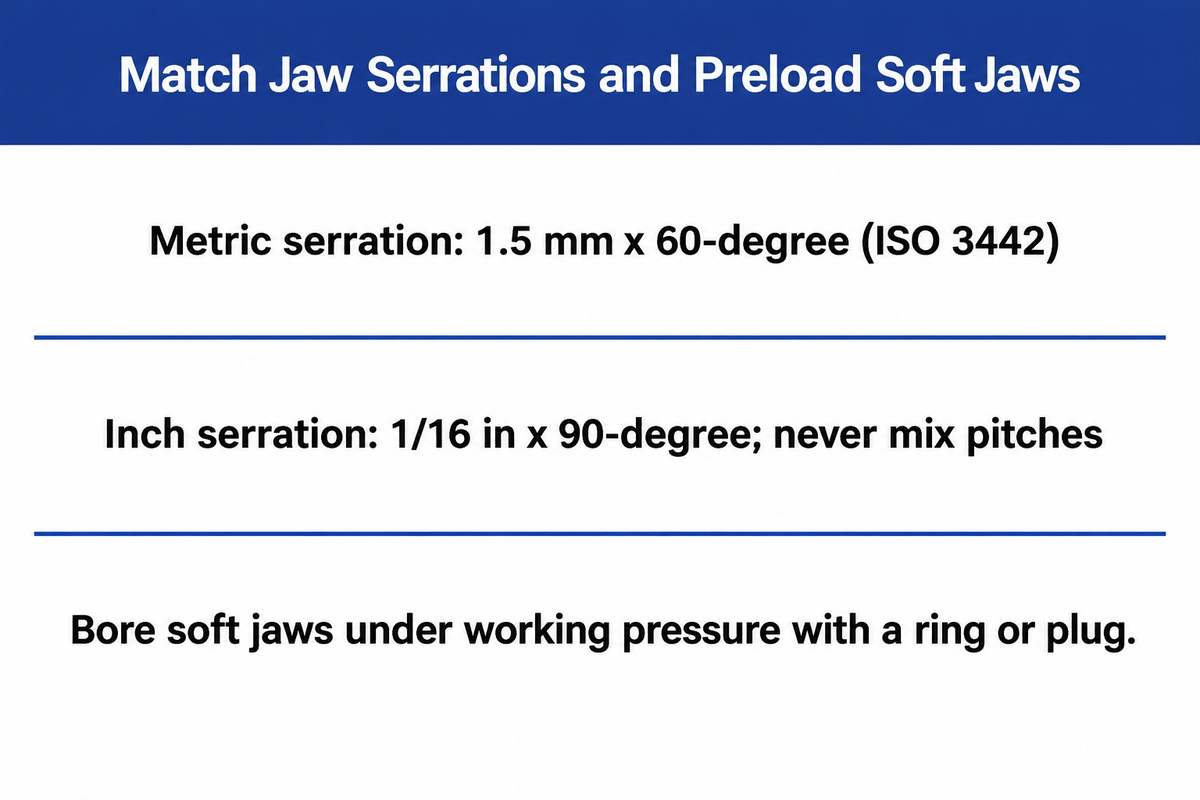
Two-piece chucks separate internal master jaws from replaceable top jaw sets. That interchangeable jaw layout cuts tooling cost when interface dimensions and bolts match the master jaws and jaw mass and height stay within chuck limits. In ISO 3442, Parts 1 and 2 cover tongue-and-groove jaw interchangeability, while Part 3 covers serrated power-chuck jaws and accuracy tests. Never bolt imperial 1/16 in x 90-degree serrated top jaws onto metric 1.5 mm x 60-degree (or 3.0 mm x 60-degree) master jaws. Mismatched pitch and flank angles contact only tooth tips and shear serrations under load.
Can I switch jaw configurations on a manual lathe chuck?
Manual scroll chucks usually employ separate matched sets of one-piece inside and outside jaws. Reversible one-piece jaws and interchangeable top jaws only work on chucks built for them. Reinstall one-piece scroll jaws in the manufacturer’s specified slot sequence so all scroll teeth center together.
When using reversible jaws on large diameters, WorkSafe Victoria Zone 3 guidance states that full scroll thread engagement must be maintained to prevent the jaws from stripping or projecting beyond the rim. In soft jaws on manual or power chucks, close concentricity is difficult to achieve and is only possible with clamping preload when boring. In a Practical Machinist shop case, bored soft jaws still showed 0.008” runout because the plug sat pinched at the jaw tips and the clamping pressure was adjusted post-bore. To preload jaws in the production clamping direction, a boring ring, spider, or plug at the required working pressure should be used. A power or scroll chuck offers consistent bore repeatability only if guideway backlash is taken up at the actual gripping position.
Quick-change jaw and collet upgrade payback calculation
Frequent jaw swaps mean quick-change jaws or collets can be changed more quickly, resulting in reduced chuck setup times. On a dedicated single-part line, with no jaw or collet changes, improvements in changeover time don’t result in hardware premium recovery. Estimate the number of setups needed to repay choosing the right upgrade by dividing incremental hardware cost by labor and machine value saved per changeover. Compare quick-change jaws against the report benchmarks below.
In Cutting Tool Engineering’s quick-change jaw report, unbolting three standard top jaws and re-cutting soft jaws takes 15 to 20 minutes, and standard chucks initially cost 30% to 40% less on a new lathe. By comparison, SCHUNK’s PRONTO system swaps one jaw insert in 5 seconds (15 seconds per 3-jaw set) with 25-micrometer (0.00098 in) repeatability. QCS’s J-LOC system swaps jaws in 10 seconds. Across 10 jaw sets reused 10 times on a 10-inch (254 mm) Kitagawa 3-jaw chuck, QCS documented $5,630 total cost for standard soft jaws ($630 jaws plus setup labor). J-LOC totaled $2,737 ($2,130 quick-change hardware plus 10-second swaps), saving $2,893. Dead-length collet pricing varies by spindle size and vendor quote, so evaluate collet upgrades with the same setup-minute formula plus spare-collet inventory costs.
Jaw-Change Downtime Break-Even Table
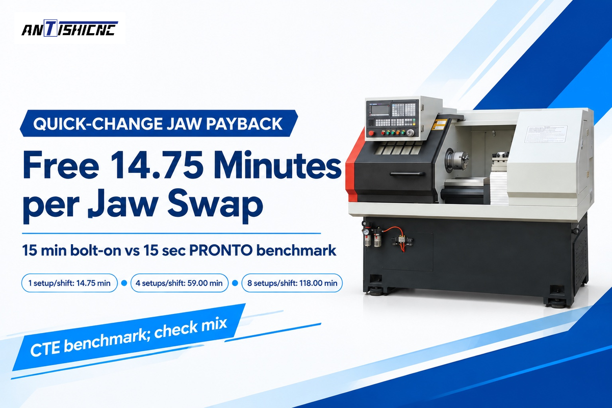
As described in NIST AMS 100-62 investment evaluation guidance, to use the simplified payback method, divide the incremental investment by the periodic savings and state every shop assumption. Using published Cutting Tool Engineering benchmarks of 15 minutes (900 seconds) for a standard three-jaw bolt-on swap versus 15 seconds (0.25 minutes) for a three-jaw PRONTO quick-change swap, each swap frees 14.75 spindle minutes. Multiply freed minutes per shift by your shop minute rate to test payback against quoted hardware delta.
| Jaw Setups per Shift | Standard Bolt-On Time (at 15 min) | Quick-Change Time (at 15 sec) | Spindle Minutes Freed per Shift |
|---|---|---|---|
| 1 setup per shift | 15.0 min | 15 sec (0.25 min) | 14.75 min freed |
| 2 setups per shift | 30.0 min | 30 sec (0.50 min) | 29.50 min freed |
| 3 setups per shift | 45.0 min | 45 sec (0.75 min) | 44.25 min freed |
| 4 setups per shift | 60.0 min | 60 sec (1.00 min) | 59.00 min freed |
| 5 setups per shift | 75.0 min | 75 sec (1.25 min) | 73.75 min freed |
| 6 setups per shift | 90.0 min | 90 sec (1.50 min) | 88.50 min freed |
| 8 setups per shift | 120.0 min | 120 sec (2.00 min) | 118.00 min freed |
| 10 setups per shift | 150.0 min | 150 sec (2.50 min) | 147.50 min freed |
| 12 setups per shift | 180.0 min | 180 sec (3.00 min) | 177.00 min freed |
There are three operating boundaries that make quick-change tooling an unwise choice of chuck. First, on a dedicated lathe recovering zero setup minutes from not swapping jaws, focus on turning feeds and speeds. Second, forgings beyond a collet’s collapse range jam collet sleeves. Third, proprietary base jaws tie your selection of lathe chucks to one manufacturer’s insert blanks. Check blank pricing before setting up CNC turning and milling cells. With high-mix schedules where freed spindle value is greater than base-jaw and insert outlay, quick-change workholding should be selected as an essential tool. Cutting logged setup downtime improves shop efficiency with the right lathe chuck or right chuck package.
Chuck standards, major manufacturers, and CNC lathe RFQ checklist

A complete lathe purchase order lists exact ISO mounting, jaw and safety standards and workpiece drawings, so the builder sizes the spindle nose, rotary cylinder, drawtube and chuck. Specifying only an outer chuck diameter leaves critical spindle taper, stroke, speed and bar clearance undefined before quotation.
Understanding the different types of workholding standards avoids interface mismatches in machining and manufacturing tenders. In the ISO/TC 39/SC 8 catalogue, ISO 702-1 through ISO 702-4 define conical, Camlock, bayonet, and cylindrical spindle noses. Buyers retrofitting older European manual lathes sometimes encounter DIN 6350 cylindrical-recess references; its dimension tables are outside the verified ISO record here, so request exact recess and bolt-circle drawings from the vendor. ISO 3089:2005 applies only to static geometrical tests on manual self-centering chucks with one-piece jaws. ISO 3442-1 and ISO 3442-2 address connecting dimensions and interchangeability for two-piece-jaw chucks, while ISO 3442-3 specifies geometrical accuracy tests for power-operated chucks. Power-chuck design safety and grip-force limits fall under ISO 16156:2004, now under active revision as ISO/WD 16156 (Edition 2), registered in September 2026 and in working-draft study as of October 2026.
ISO/TC 39/SC 8 maintains separate standards for spindle noses (ISO 702), manual one-piece-jaw scroll tests (ISO 3089), two-piece jaw interfaces and power-chuck accuracy (ISO 3442), and chuck safety (ISO 16156).
Comparing types of lathe chucks available and different types of chucks available across specialist builders also helps define sourcing scope. Technical sources cited here cover Kitagawa (wedge-hook chucks), SCHUNK (PRONTO jaws), Pratt Burnerd (counter-balanced chucks) and QCS Workholding (J-LOC jaws). Published data also includes Forkardt Hardinge and Royal Products (collets), Wagner Magnete and HVR Magnet (magnetic chucks), and Tonfou (CNC jaws). Industrial catalogs (Penn Tool Co.) list replacement manual chucks. Verify model ratings on current maker datasheets. All chuck trademarks are owned by the respective companies. ANTISHICNC builds CNC lathes, universal lathes, vertical lathes, and pipe threading lathes with matched manual, hydraulic, or pneumatic packages, alongside guides on capstan and turret lathes.
Specifying workholding for a new ANTISHICNC lathe? Send your part drawing with raw and finished diameters, minimum wall thickness, bar-feed versus chucked length, material grade, target TIR, maximum RPM, and shift setup count. Explore our CNC lathe machines so our engineers can match spindle nose, drawtube bore, rotary cylinder, and common types of jaws before quotation.
Frequently asked questions
Can a 3-jaw scroll chuck hold square bar stock safely?
No, a standard 3-jaw scroll chuck can’t hold square bar stock safely during metal turning. Three jaws set at 120 degrees can’t meet four 90-degree flats symmetrically, creating unstable corner contact and a serious part ejection hazard under cutting torque. Clamp square bar in a 4-jaw independent chuck, a 4-jaw self-centering scroll chuck, or a square collet.
What does the number 6 mean in an A2-6 or D1-6 spindle mount?
The number 6 denotes the standardized ISO 702 spindle-nose size code (built on the 7-degree 7-minute 30-second short taper in ISO 702-1:2009), not a 6-inch chuck diameter. An A2-6 nose uses an outer bolt circle, while a D1-6 nose uses six camlock studs. Mounting one style onto the other requires a machined adapter plate.
Why do soft jaws need a clamping ring or plug while being bored?
Use a clamping ring, spider, or plug to preload master-jaw guideway clearance in the production clamping direction during soft-jaw boring. Boring soft jaws without preload can cause diameter, taper, or contact errors once cutting clamp pressure takes up clearance and deflects the jaws. Match boring hydraulic pressure to part pressure.
Do 1.5 mm x 60° metric top jaws fit inch-serrated master jaws?
No, metric 1.5 mm x 60-degree top jaws don’t fit imperial 1/16 in x 90-degree master jaws. Mismatched pitches engage only tooth tips and shear serrations.
When should a CNC shop choose a dead-length collet chuck over a pullback collet?
Choose a dead-length collet chuck when second-operation parts bank against an internal Z-stop or transfer to a sub-spindle with tight shoulder-length tolerances. Dead-length designs push a tapered sleeve forward over a stationary collet, keeping the workpiece fixed axially during clamping. Standard 5C and 16C pullback collets draw rearward into the spindle taper instead. Whenever incoming bar diameter varies within mill tolerance, pullback action shifts axial Z-position slightly. Weigh dead-length axial accuracy against the added nose overhang inside compact lathe turrets.
Does a larger chuck diameter always fit the same lathe spindle?
No, maximum chuck diameter is capped by bed swing, guard clearance, bearing load limits, rated chuck RPM, and ISO 702 bolt-circle compatibility.
What workpiece and tooling details belong in a lathe chucking inquiry?
Send a part drawing showing raw stock and finished diameters, minimum wall thickness, bar-feed length versus chucked blank mass, and alloy grade. Specify magnetic permeability if evaluating radial-pole magnetic chucks for large rings. Include target concentricity (TIR), planned maximum spindle RPM, batch size, and setups per shift. State whether your operators prefer manual scroll or independent jaws, serrated hydraulic jaws, or quick-change collets. Those inputs match the ISO 702 nose, cylinder stroke, drawtube bore, and dynamic grip.
Scope Note: ANTISHICNC machine bore and speed figures come from official supplier technical quotations; dynamic force and shift-minute examples state their calculation inputs explicitly.
References & Sources
- Safe use of metal turning lathes, WorkSafe Victoria, Zone 1 bar enclosure and Zone 3 chuck selection controls.
- Guide to Smart Investment Tools (AMS 100-62), National Institute of Standards and Technology (NIST), October 2024.
- ISO 702-1:2009 Machine tools: Connecting dimensions of spindle noses and work holding chucks, Part 1: Conical connection, International Organization for Standardization.
- ICS 25.060.20 Workholding spindles and chucks (ISO 702, ISO 3089:2005, ISO 3442, ISO 16156), International Organization for Standardization.
- ISO/WD 16156 (Edition 2) Safety requirements for the design and construction of work holding chucks, International Organization for Standardization.
- ISO/TC 39/SC 8 Workholding spindles and chucks catalogue, International Organization for Standardization.
- CN103611948A Slender-shaft three-jaw chuck clamping method, Google Patents public record.
- Quick-Change Jaw Systems for Chucks Offer Multiple Benefits, Cutting Tool Engineering.
- When to Use a Collet Chuck, Modern Machine Shop.
- Workholding and Quick-Change Automation Overview, International Manufacturing Technology Show (IMTS).