




The feeds and speeds for stainless steel include the cutting velocity and the rate of feed that let a tool form a chip without overloading its edge. Start with the operation: Norseman lists 30–50 SFM for HSS drilling, while BSSA gives different turning values for annealed 304/316. Milling requires the exact end-mill series, diameter and engagement.
- Cutting speed: m/min or surface feet per minute, SFM.
- Milling feed: mm/tooth, converted to mm/min using effective flutes and RPM.
- Turning and drilling feed: mm/rev or in/rev.
- Material: grade plus annealed, cold-worked or heat-treated condition.
Acquiring a CNC milling machine requires a shop to consider more than a high maximum spindle speed. The relevant question is whether the spindle, workholding and coolant configuration can sustain the cut through the entire length of the feature.
- Flood coolant isn’t the default for every stainless milling cut.
- A lower RPM changes the required feed in mm/min when chip load is held constant.
- Per-revolution programming behaves differently: the programmed feed per revolution can remain unchanged.
- A faster cut earns its tooling premium only after edge consumption, tool changes and accepted parts are counted.
Stainless steel speed and feed chart: start by operation
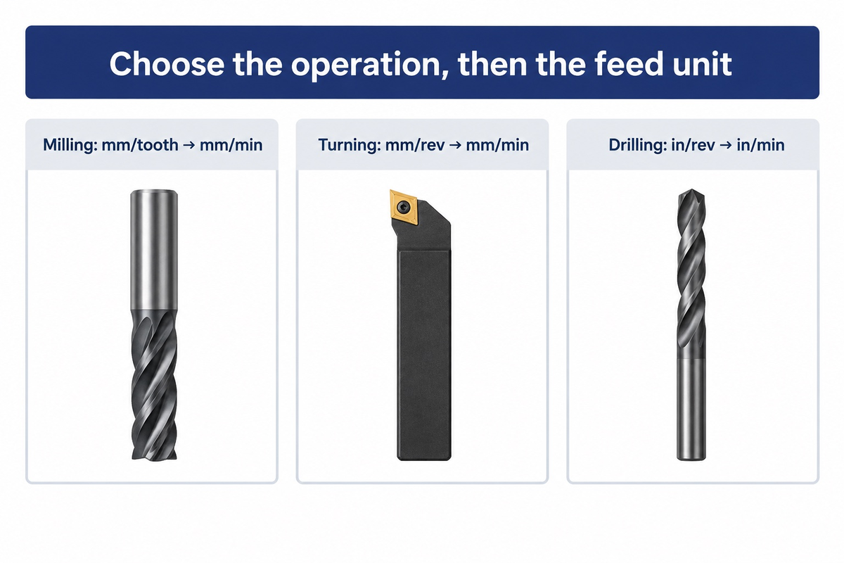
For annealed wrought 304, 316 and 321 at 160 HB, BSSA’s single-point turning table gives 95 m/min for disposable carbide roughing at 3.8 mm depth and 0.38 mm/rev feed. The following finishing row uses different settings. Drilling or milling tables must be chosen accordingly.
What is the cutting speed for stainless steel?
For stainless steel HSS drilling, Norseman provides 30-50 SFM; the cutting velocity is the surface velocity at the cutting edge and is selected based on the tool and the operation. BSSA provides a turning table that separates HSS, brazed carbide and disposable carbide at stated hardness, feed and depth of cut.
Those rows answer different shop questions. A drill enters a confined hole; a turning edge cuts continuously around the work diameter; an end mill enters and leaves the workpiece. Therefore, copying turning speed to a drill program changes the thermal load and condition of chip evacuation. Use the cutting speed chart for other metals when considering materials other than stainless.
Operation-to-Setting Worked Chart
The feeds and speeds chart maintains each source’s tool classification. Rows in BSSA reflect their traditional single-point tooling, not a recent coated-insert catalog. Haas rows contain the HTPM material group labels printed on the sheet; the appropriate group is selected based on the supplier’s stock classification. This sheet does not identify M14.1 as 304 or M14.2 as 316; establish the material-group mapping with the exact cutter data before choosing either row.
| Operation and stock | Tool / source | Cutting speed | Feed and cutting condition |
|---|---|---|---|
| Rough turning, annealed 304/316/321, 160 HB | HSS, BSSA | 23 m/min | 0.38 mm/rev; 3.8 mm depth |
| Finish turning, same stock | HSS, BSSA | 28 m/min | 0.20 mm/rev; 0.5–1.0 mm depth |
| Rough turning, same stock | Brazed carbide, BSSA | 85 m/min | 0.38 mm/rev; 3.8 mm depth |
| Finish turning, same stock | Brazed carbide, BSSA | 97 m/min | 0.20 mm/rev; 0.5–1.0 mm depth |
| Rough turning, same stock | Disposable carbide, BSSA | 95 m/min | 0.38 mm/rev; 3.8 mm depth |
| Finish turning, same stock | Disposable carbide, BSSA | 112 m/min | 0.20 mm/rev; 0.5–1.0 mm depth |
| Drilling, stainless grouping | HSS drill, Norseman | 30–50 SFM (9.1–15.2 m/min) | Diameter-specific feed in/rev; drilling conditions govern adjustment |
| Milling, stainless group M14.1; 12 mm diameter | HTPM end mill, Haas | 107 m/min | 0.0559 mm/tooth; diameter 12 mm; retain chart engagement |
| Milling, stainless group M14.2; 12 mm diameter | HTPM end mill, Haas | 94 m/min | 0.0559 mm/tooth; diameter 12 mm; retain chart engagement |
Sources: BSSA, Speeds and feeds for turning stainless steels; Norseman, Feeds & Speeds for Drills; Haas HTPM metric speeds and feeds, page 2. The HTPM sheet specifies side cutting at 0.5D radial engagement and slotting at 1.0D, with separate axial-depth entries. Preserve those conditions when taking a row into a program.
304 and 316: match the grade and cutting tool
Annealed 304 and 316 may start from the same row, if the selected tooling reference classifies them together as in the example of BSSA for turning. Cold-worked stock, a different cutting edge or a different operation may change the selection. A uniform reduction across all 316 jobs may mask differences in selection.
The material condition of the purchased stock should be captured in the job packet by purchasing. A drawing that says 304 stainless tells the programmer less than a material record that identifies the product form and hardness. BSSA’s drilling guidance illustrates work hardening in austenitic grades and the difficulties cold-drawn stock can create in small or deep holes.
Free-machining 303 is deserving of its own selection discussion. BSSA distinguishes free-machining austenitic grades from the 304/316 group in the turning table. Similarly, duplex and heat-treated martensitic stainless grades are treated separately. For other material choices, consult the guide to machining stainless steel; for the present job, keep the parameter sheet tied to the grade.
When a purchase order is repeated, the successful tool code and condition of material procured can be retained. Changing to a similar-looking cutter or a different stock condition for the next purchase, even when the drawing for the part hasn’t changed, creates a new setup decision.
Carbide end mills: chip load and milling engagement
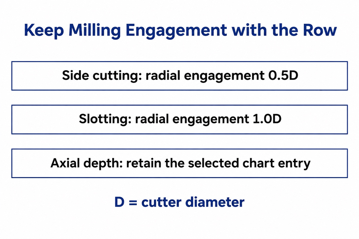
Haas’s 12 mm HTPM stainless M14.1 row pairs at 107 m/min with a feed per tooth of 0.0559 mm. This combination is valid for the stated slotting and side-cutting conditions. Applying this to a different carbide end mill would require matching geometry and engagement data, because chip space and cutting load change with the cut.
A full-width slot keeps more of the cutter engaged and gives chips less room to escape than an open side cut. During CNC machining, cutter diameter isn’t the only factor that describes a milling recipe. Flute count, radial width, axial depth and tool overhang also need to be next to the speed chart on the setup sheet. The HTPM document also advises adjustments for longer cutting lengths and less rigid conditions.
In Malekan and colleagues’ 2021 stainless end-milling study, the tool with the highest removal rate also had the fastest cutting edge wear, reaching a reported maximum of 420 μm. Geometry and coatings also varied among the tools, and the best buying lesson is to compare the complete tool-and-cut combination, rather than cite one element of the combination as the whole answer.
Cooling belongs to that combination. Sandvik Coromant’s guidance for milling different materials suggests dry rough milling of austenitic and duplex stainless to minimize thermal cracking in their insert milling context. Their finishing guidance suggests cutting fluid or mist if surface quality calls for it. For a solid-carbide tool, follow that specific tool maker’s cooling recommendation; switching off coolant midway through a proven wet process is a process change.
- Record the exact end-mill series.
- Record radial width and axial depth.
- Keep the selected cooling method consistent.
- Do not copy a side-cut row into a deep slot.
- Do not use a turning feed as milling feed per tooth.
- Do not treat every carbide coating as interchangeable.
CNC turning: cutting speed, feed and diameter

Turning uses the diameter of the workpiece to convert cutting speed into RPM and sets tool advance using feed per revolution. In a lathe programmed in mm/rev, the feed setting can stay constant as the RPM changes. The resulting feed in mm/min automatically changes. There’s a limit to the RPM of the spindle based on the setup of the chuck and workpiece.
The difference is important when comparing CNC lathes. The maximum spindle speed described in a catalog is a specification of the CNC lathe. However, the allowed operating speed also depends on workholding, tool limits and the part. With constant surface speed, RPM is increased as the tool approaches a smaller diameter; the program needs an appropriate speed clamp for the current setup.
The University of Florida’s CNC lathe teaching examples show a speed clamp and use of constant surface speed with a fixed feed per revolution. Their example values belong to the lab’s machine and chuck. The lesson on control mode is useful; reducing actual RPM doesn’t require a proportional reduction in feed set in mm/rev in the program when preserving the same feed per revolution.
BSSA connects turning speed to depth and feed. Its roughing and finishing rows form separate packages. Moving to a light finishing cut while retaining every roughing assumption can put the edge into a previously hardened surface. Leave sufficient finishing allowance and choose the finishing geometry before the final roughing pass.
Drill speeds: HSS, cobalt and carbide
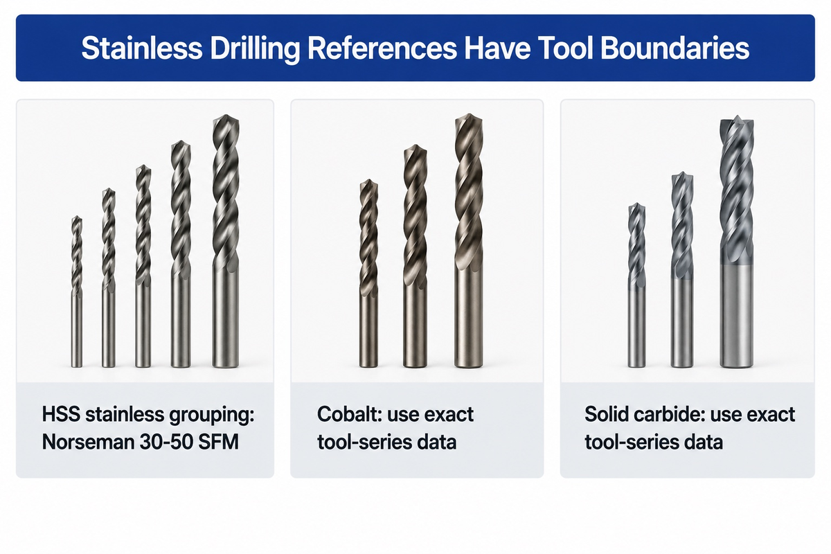
Norseman’s HSS drill reference lists stainless steel at 30-50 SFM and specifies feed by drill diameter, with feed expressed in inches per revolution. Cobalt and solid carbide drills use their own tool-series data. A verified 316-specific numeric row for either type isn’t established by these references, so the HSS range is the only drilling speed quantified here. Hole depth and coolant delivery determine if a given drill setting can clear chips through the hole.
High speed steel is still a feasible option for stainless drilling. With cobalt-bearing HSS, web thickness and geometry also affect how the drill cuts. Solid carbide drills need a rigid compatible system and the coolant arrangement specified for the tool. A carbide-tipped holecutter is yet another tool type; its RPM table isn’t a solid-carbide drill table.
In the HSS example, Norseman’s diameter table gives 0.004–0.010 in/rev in the 1/4–1/2 inch band. At an assumed 40 SFM and an exact 1/2 inch diameter, the calculated tool speed is about 306 RPM. An assumed 0.004 in/rev feed then produces about 1.22 in/min. These are conversions of selected reference inputs, with the drill condition and hole geometry still part of the setup.
When comparing a drill press to radial drilling machines, the available speed steps and feed control at the desired diameter should be considered. A sharp drill bit can still fail when chips pack in the hole. BSSA’s drilling and reaming guidance stresses maintained cutting feed, chip escape and avoiding dwell. Use the drillmaker’s depth-specific cycle rather than applying a single peck interval to every drill.
Calculate RPM and feed rate from cutting data
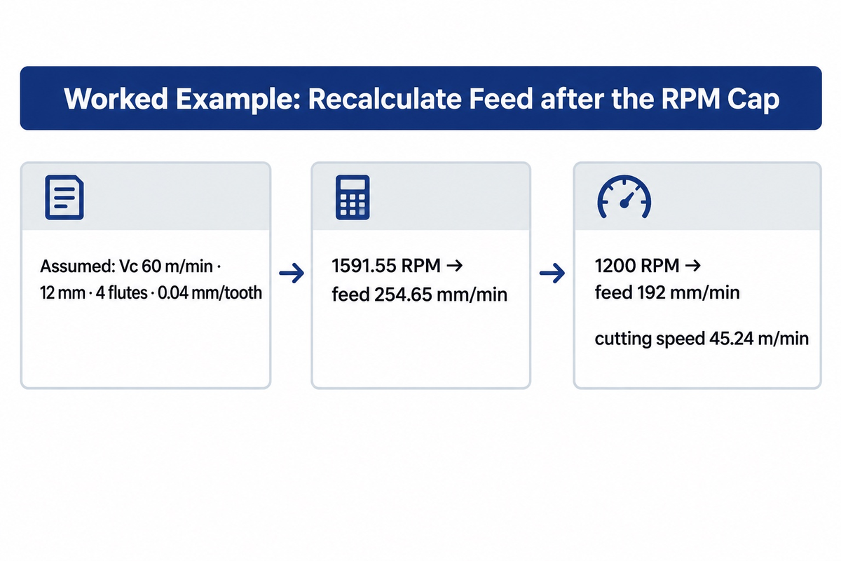
For metric milling, the speed in RPM equals 1000 multiplied by the cutting speed in m/min divided by the product of π and the cutter diameter in mm. Table feed equals RPM times effective flutes times feed per tooth. Set the spindle speed to the allowed RPM prior to computing the feed in mm/min.
How Do Machinists Calculate Cutting Feeds and Speeds?
Machinists determine RPM from diameter and surface speed and determine linear feed using the correct advance unit. Milling multiplies RPM times feed per tooth and effective flutes. Drilling and turning multiply RPM by feed per revolution. These relationships are shown in Mitsubishi Materials’ cutting formulas and University of Florida’s speeds and feeds notes.
Use the metric pairs n = 1000 × Vc / (π × D) and Vf = n × z × fz for milling. In inch units, n = 12 × SFM / (π × D), where D is in inches. For per-revolution operations, Vf = n × fn. Keeping mm/tooth and mm/rev separate prevents an unwanted extra multiplication by flute count. The quantities across materials are explained on the feeds and speeds fundamentals page.
Assumed inputs for a worked example: a 12 mm, four-flute end mill, Vc = 60 m/min and fz = 0.04 mm/tooth. These inputs illustrate the arithmetic; they aren’t a toolmaker recommendation for an unnamed cutter. The calculation gives 1000 × 60 ÷ (π × 12) = 1591.55 RPM, then 1591.55 × 4 × 0.04 = 254.65 mm/min.
Suppose that setup permits only 1200 RPM. Retaining 0.04 mm/tooth requires 1200 × 4 × 0.04 = 192 mm/min. Surface speed becomes π × 12 × 1200 ÷ 1000 = 45.24 m/min. Leaving the old 254.65 mm/min feed would raise feed per tooth to about 0.0531 mm. The speed cap has changed the cut, not merely the display.
For a lathe running in feed-per-revolution mode, retain the selected fn setting when preserving feed per revolution. For example, an assumed 0.20 mm/rev at 1200 RPM corresponds to 240 mm/min. The controller’s feed mode determines what the programmed F value means; machine-specific codes must follow its manual.
Work hardening and tool wear: correct the cause
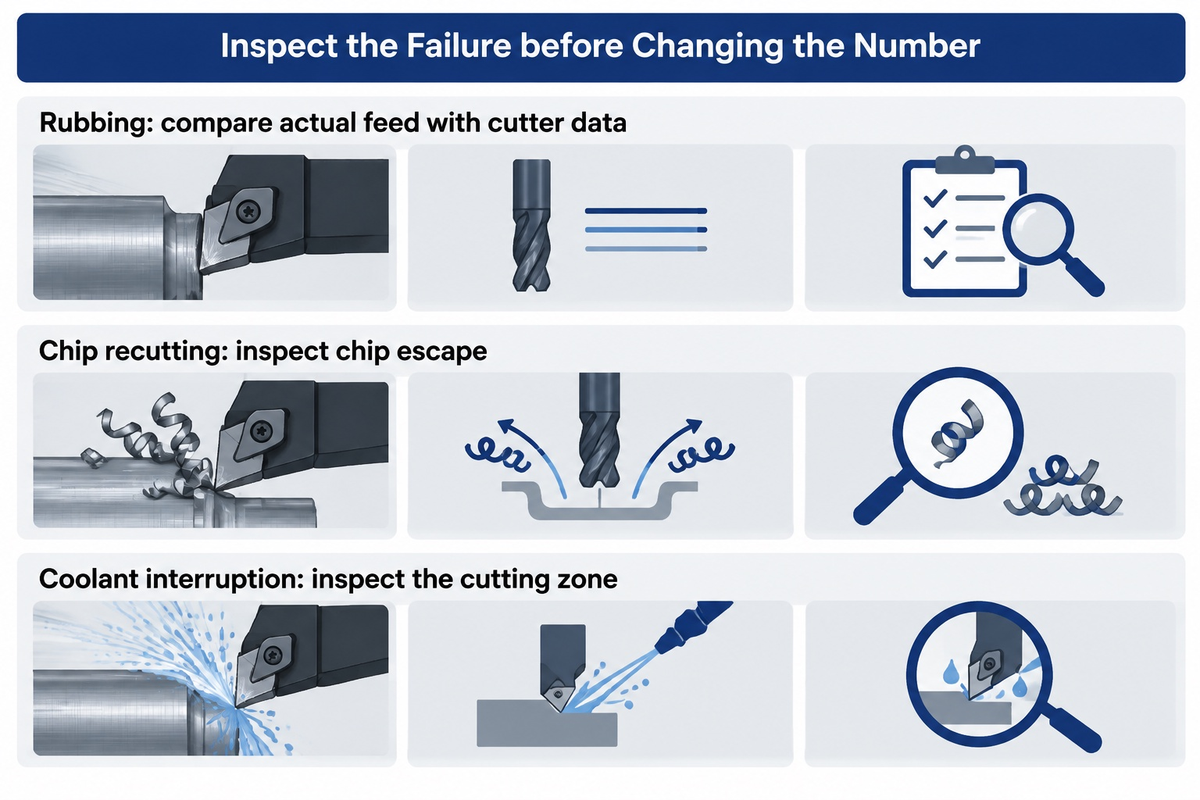
When work hardening or tool wear occurs, check for rubbing, chip recutting, unstable engagement and coolant interruption before changing speed or feed. These conditions cause different symptoms. Look at the point of tool failure and how the chips escaped before changing speed or feed.
What happens if feed rate is too low?
When working with work-hardening stainless steel, a very low feed can cause the cutting edge to rub or plough instead of cutting the desired chip. This threshold changes with edge geometry, wear on the edge and engagement. Very low feeds should therefore be investigated, rather than assumed, as the cause of failure.
Elkaseer and colleagues’ 2019 study on the precision turning of 316L also reported a non-linear relationship between feed and surface roughness as the edge condition changed. From the microscopic cutting conditions, a minimum feed for ordinary end mills shouldn’t be assumed. The correct action is to compare the running feed with the exact cutter data and check the edge condition instead of assuming a universal chip-load floor.
One 2018 Practical Machinist discussion of a 304L job illustrates the problem. Jaxian reported a broken cutter during full-width slotting, then very conservative feeds and a long cycle. Replies debated if feed itself caused the break. Jaxian later suspected the right-side coolant nozzle was leaving the deep cutting zone poorly covered. That suspicion was not a confirmed failure analysis, but it gives an operator a useful inspection point: coolant on the surface does not guarantee chip clearance at the bottom of a slot.
The same discussion also includes a dry-machining example with low radial engagement. This cut is also different from the original deep slot. A separate 316 manual-milling discussion also attaches a backlash constraint to a climb-milling suggestion. Carrying those details with the experience avoids turning an individual success into an instruction for a different machine.
Tool life and surface finish are different factors. A 2021 finishing end-milling study on AISI 316 assessed the effects of dry cutting, MQL and nanoparticle-assisted MQL and considered surface quality and power consumption as responses. Improvements in these responses should be assessed as such while choosing a finishing process.
Tool cost per part and CNC machine limits
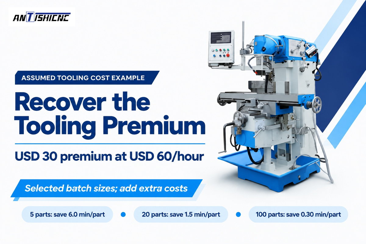
A USD 30 tooling premium needs 30 minutes of saved machine time to recover its price at an assumed USD 60 per hour. This assumes no change in edge consumption, tool changes or rejects. The savings per part will vary with batch size, which the table illustrates.
Tooling Break-Even Cut-Time Table
Assumed inputs: one option adds USD 30 in tooling cost for the batch; machine time is valued at USD 60/hour, or USD 1/minute. Both options make the same number of accepted parts. Setup, consumables and edge consumption are initially held equal. Required saved minutes per part = 30 ÷ batch quantity.
| Accepted batch quantity | Required saving per part | Required batch saving |
|---|---|---|
| 5 parts | 6.0 min | 30 min |
| 10 parts | 3.0 min | 30 min |
| 20 parts | 1.5 min | 30 min |
| 25 parts | 1.2 min | 30 min |
| 30 parts | 1.0 min | 30 min |
| 40 parts | 0.75 min | 30 min |
| 50 parts | 0.60 min | 30 min |
| 75 parts | 0.40 min | 30 min |
| 100 parts | 0.30 min | 30 min |
In a hypothetical 20-part order, a saving of 1 minute per part returns USD 20 at that time value, leaving USD 10 of the premium unrecovered. A saving of 2 minutes returns USD 40 before any additional costs. If the faster option consumes another edge or adds inspection time, add those costs before comparing the accepted-part total. For that 20-part batch, carbide pays back only when measured time savings exceed 1.5 minutes per accepted part plus those additional costs. Actual 304 tool-life and cycle-time results for the proposed two tools are needed to decide which clears that threshold. Minquiz and colleagues’ 2023 milling cost model likewise includes tool costs, replacement time and shop rate in its own case assumptions.
The machine can potentially block savings. Scott Smith’s explanation of spindle power and torque limitations explains the importance of power at working RPM. A higher nameplate rating at another speed doesn’t equal the same available power at the cutting speed.
| Constraint | Filled example or signal | Buyer action |
|---|---|---|
| RPM limit | Worked milling example caps at 1200 RPM | Compare feed and surface speed after the cap |
| Power at cutting speed | Available torque/power curve at the selected RPM | Match the proposed cut to that point on the curve |
| Tool change and edge use | 20-part example values saved minutes at USD 1/min | Subtract additional edge and change costs |
| Feature access and chips | Deep slot can shadow a coolant nozzle | Evaluate delivery and chip escape on the actual feature |
Cutting-data sources for your stainless setup
Use a source relevant to the decision. The toolmaker can provide cutting data, the steel record identifies material condition, and the machine supplier can provide spindle and equipment information. For a new setup, take the same tool code and cutting engagement into the machine inquiry. That way the proposed configuration can be compared to the intended cut.
Haas publishes HTPM sheets for tool series; Norseman provides HSS drilling guidance; Sandvik Coromant offers milling guidance by material and operation; Mitsubishi Materials provides cutting formulas. Those resources help at different steps of CNC milling programming. Leave original units beside chosen values.
For a controlled tool-life comparison, ISO 3685:1993, Tool-life testing with single-point turning tools, provides a public scope covering turning tools, workpiece conditions and test reporting. Its catalogue lists Edition 2 as current. The standard’s scope concerns testing, while a selected tool’s data sheet supplies the cutting recommendation.
ISO 3685 describes “recommended procedures for tool-life testing” within its single-point turning-tool scope.
Planning a stainless job on ANTISHICNC equipment? Send the part drawing, material grade and condition, largest and smallest cutting diameters, tool series and proposed engagement. Include the required batch quantity and hole depth where relevant. Start with the appropriate vertical machining centre or lathe configuration, then compare spindle, feed and coolant details against that job.
Frequently asked questions
Can I use the same feeds and speeds for 304 and 316?
Yes, when the selected tool’s reference groups both grades in the same material condition and operation. BSSA’s annealed turning example does this. A different stock condition or cutter can require another row. Keep the chosen tool family, depth of cut and feed units together instead of applying a fixed percentage change.
Why do my tools wear quickly or break?
Excessive speed, rubbing, chip packing, unstable holding or interrupted coolant delivery can cause rapid tool wear or breakage. Inspect the wear pattern and cutting conditions to select the correction. Compare the actual feed and engagement with the exact tool’s data. A broken edge by itself doesn’t identify which condition caused the failure on that job.
Can a drill press machine stainless steel with HSS?
Yes, a suitable drill press can use an HSS drill for stainless when it provides the required speed, rigid workholding and controlled cutting feed. Norseman’s reference lists 30–50 SFM for its stainless grouping. Drill diameter sets RPM, while hole depth and chip evacuation affect the cycle and the needed coolant delivery.
Does a higher spindle speed always mean faster machining?
No. Higher RPM can increase cutting feed at a retained chip load, but tool wear, power limits and extra tool changes can offset the gain. Compare total cycle time and accepted-part cost at the proposed operating conditions before valuing the change.
Can I use a speed chart for a different cutter diameter?
Use the chart’s diameter-specific data or its stated scaling method. Cutting speed converts to a different RPM when diameter changes, and the recommended feed per tooth can change too. Keeping the same RPM and linear feed would therefore create a different cut. For an end mill, retain the actual effective flute count in the feed calculation. For drilling or turning, use feed per revolution. Recalculate from compatible source inputs rather than copying the displayed RPM alone.
Should I use a peck cycle when drilling stainless steel?
Use a peck cycle when the chosen drill’s depth-specific instructions require withdrawal to clear chips. Through-tool coolant and a different drill design can call for a different cycle. Avoid dwell and chip packing. A peck interval from an HSS reference shouldn’t automatically govern another drill design.
What information belongs in a stainless machining enquiry?
Include the drawing revision, stainless grade, material condition, operation and required batch quantity. Add cutter or drill series, cutting diameter, radial and axial engagement, or hole depth. State the intended feed mode and coolant delivery method. For machine selection, include the part’s workholding needs and the required spindle range. Those inputs let the supplier compare the proposed equipment with the intended process while keeping tooling, machine capacity and finished-part requirements distinct.
Compare cutting data within the named tool series and material conditions. Worked cost and RPM examples use stated assumptions.
References & Sources
- Speeds and feeds for turning stainless steels, British Stainless Steel Association, annealed stock and tool-specific starting data.
- Speeds and feeds for drilling and reaming stainless steels, British Stainless Steel Association.
- Speeds and Feeds, University of Florida Design & Manufacturing Laboratory, instructional formulas.
- CNC Lathe Resources, University of Florida, feed modes and workholding examples.
- Cutting edge wear in high-speed stainless steel end milling, Malekan et al., 2021, university-hosted abstract.
- FEM-based study of precision hard turning of stainless steel 316L, Elkaseer et al., 2019, KITopen abstract.
- AISI 316 finishing end-milling cooling study, 2021 author abstract indexed by PubMed.
- Sustainable assessment of a milling manufacturing process based on economic tool life and energy modeling, Minquiz et al., 2023.
- Spindle power and torque limitations, Scott Smith, Cutting Tool Engineering.
- ISO 3685:1993 public catalogue and abstract, International Organization for Standardization.